PIV-TV1
National Wireless, Inc.
Click to zoom
Application Details
- Equipment Class
- DXX - Part 15 Low Power Communication Device Transmitter
- Date of Grant
- Oct 18, 2001
- Application Purpose
- Original Equipment
- Date of Application
- Jun 25, 2001
- Frequency Range
- 906.00000000 - 924.00000000
- Company
- National Wireless, Inc.
- Country
- United States
Documents & Files
Document Text
Text extracted from the exhibit documents filed with the FCC. Open a document above to read the original.
Users Manual
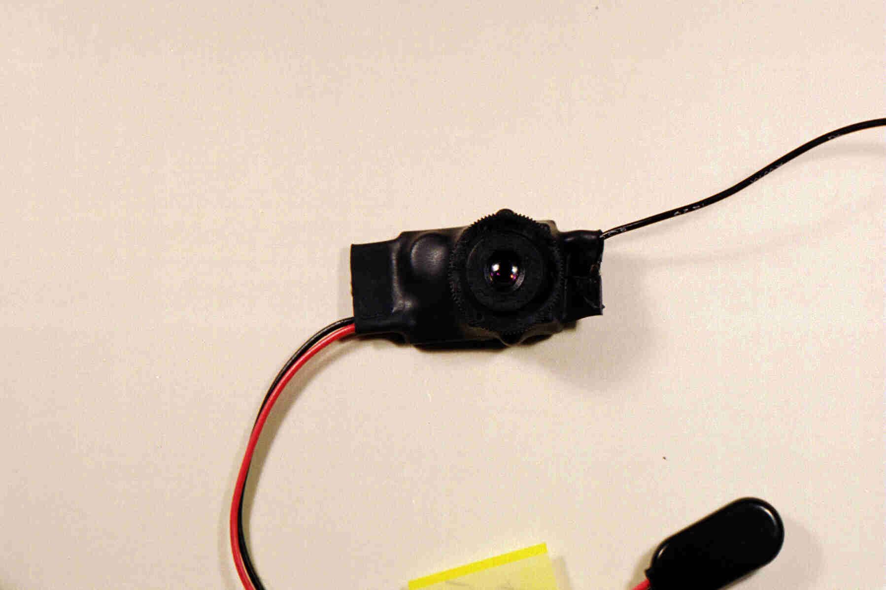
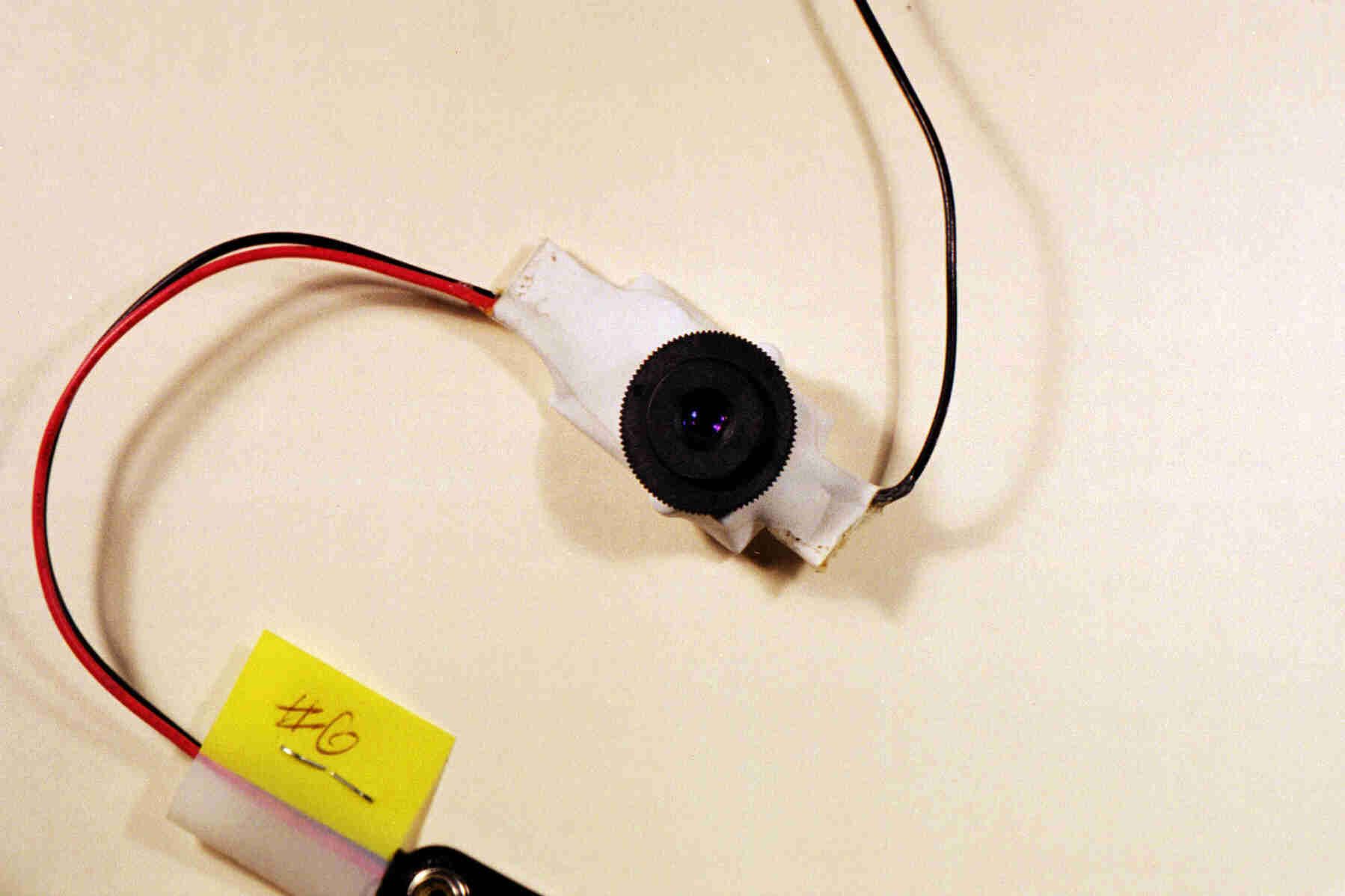
1 Installation and use of Securetek ST-100 Series Wireless Television TransmitterCongratulations! You have purchased a quality product, designed andmanufactured exclusively for Securetek, Inc. This transmitter is available inseveral frequencies, and several versions. Please determine from the table beloww hich version you have.The transmitters with an included camera (Models ST 100B- and ST 100BC-)are plug and play. There are no adjustments. Just mount the camera/transmitterunit, attach a 9 Volt battery, and you are on the air! Don = t forget to tune your television receiver to the frequency of the transmitter. Table I. Securetek transmitters Mode l numbe r Fre que ncy Came ra ST-101B-906 906 MHz None ST-101B-916 916.5 MHz None ST101B-920 920 MHz None ST100B-906 906 MHz B&W ST100B-916 916.5 MHz B&W ST100B-920 920 MHz B&W ST100BC-906 906 MHz COLOR ST100BC-916 916.5 MHz COLOR ST101BC-920 920 MHz COLOR INSTALLATION Mounting transmitterWhile the transmitter can be mounted in any direction, the most commoninstallation will pl ace the antenna vertically above the camera/transmitter unit. The antenna must be kept free from obstructions. You can maximize transmissiondistance by keeping this antenna straight, free from obstructions and in the verticalposition.Attaching a camera (models without camera only) 2 FCC ID: PIV-TV1 The camera video lead must be connected to the RCA jack lead that is attached tothe transmitter. If you are attaching an RCA plug to the camera video cable, becareful to observe the proper connections. The video lead (usually a white oryellow wire) must be connected to the center pin of the connector. The shieldwire must be soldered to the ground ring of the RCA plug.The camera must have an output peak-to-peak video signal level of 1.0 Volts orless. The video level from most A board @ cameras is 1.0 Volt peak-to-peak. If the camera video output exceeds 1.0 Volt, or if you are unsure about the video levelfrom your camera, DO NOT USE THIS TRANSMITTER until you have thecamera output video level measured and adjusted by a competent technician.AdjustmentsAll of the Securetek ST 100 series transmitters are plug and play. There are noadjustments. Just mount the camera/transmitter unit, attach a 9 Volt battery, andyou are on the air! Don = t forget to tune your television receiver to the frequency of the transmitter.If you have purchased a Securetek receiver or receiving converter, see the tuninginstructions packed with the instrument. Information for users This unit is identified by the FCC certification identification number:This unit is manufactured by: Distributed by: National Wireless, Inc. Securetek, Inc. 221 Pine St. 7152 SW 47 th St. Florence, MA 01062-1267 Miami, FL 33155 3 This device complies with Part 15 of the FCC Rules. Operation of thisdevice is subject to two conditions: (1) This device may not cause harmfulinterference, and (2) This device must accept any interference received,including interference that may cause undesired operation. Modifications or changes.This device is approved for unlicensed use by the Federal CommunicationsCommission(FCC) under 47 CFR 15.249 (a paragraph of the rules and regulationsof the FCC). Any modifications or changes to this device are expressly forbidden,and could void the user = s authority to operate this equipment. Modifications or changes will void the warranty.Reducing interferenceInterference from cordless telephones and other wireless products. This deviceoperates in the same band as 900 MHz cordless telephones and other wirelessproducts. If interference is detected in the telephone (usually a buzzing sound),this device should be re-oriented or moved until the interference is eliminated. This device must not be allowed to cause interference to these telephones.Multipath is another form of interference that can distort the received picture.Multipath is the result of a signal traveling from the transmitter to your TVreceiver in two, or more paths. One of these paths is a signal bouncing from ametallic object. Multipath distortion can usually be reduced by re-orienting, ormoving, the transmitter, or receiver, or both. Two transmitter operation When two transmitters are operating nearby, two different frequencies must beused so that the transmitters do not interfere with each other. In this case, werecommend that one of the transmitters operate at 906 MHz. The other mayoperate at either 916.5 MHz or 920 MHz.8 National Wireless, Inc., June, 2001
Attestation Statements
N ational W ireless , INC . 221 Pine St. Florence, MA 01062 413-586-5111 413-586-4422 FAX Re: FCC ID PIV-TV1 731 Confirm Number EA101495Correspondence Ref No. 20805 Justification for Confidentially Confidentiality is requested for the block diagram, schematic diagram, parts list and description of operation pursuant to 47CFR0.457 and 47CFR0.459. Confidentially is requested to ensure a competitive advantage. We feel that many potential competitors would not have a microwave engineer on staff, and would most likely be unable to duplicate the oscillator, and amplifier filter / impedance matching elements of the circuit without access to the information requested to be confidential. In the following, we describe the reasons why we consider some elements of the circuit as a trade secret, then we describe how we plan to maintain confidentiality A. Oscillator We have analyzed several non-certified television transmitter circuits for use at both 434 MHZ and 916 MHZ. We have found that, in most cases, these circuits are copies of each other. Of the several problem areas that we saw (lack of output matching, no harmonic filtering, insufficient vias to the ground plane, etc) the predominate is their inability to construct a stable SAW oscillator, particularly for 916.5 MHZ. Here these circuits use a purchased oscillator. We conjecture that these potential competitors do not have a microwave engineer available. The cost differential between the purchased oscillator (about $8.40 each, per thousand pieces) compared to our cost of approximately $1.96 (each, per thousand pieces) gives us a large competitive edge. This is our best trade secret, and forms the basis for our confidentially request. The remainder of our confidentially request is to keep confidential the engineering component choices that we made to develop a quality product. 1. Course frequency control of a SAW stabilized oscillator A Surface Acoustic Wave (SAW) oscillator is unlike a crystal oscillator in that the resonating device is actually an LC network that is stabilized, or locked on frequency, by a SAW resonator. The frequency of this oscillator LC circuit must have an error of less than 10% of the SAW device frequency, for proper lock. We employ a Colpitts oscillator. In theory, the free-running frequency of this oscillator is determined by L1 and C2. However this frequency is substantially altered by: the parasitic values of these components, the parasitic capacitance and inductance of the circuit board, the parasitic capacitance of the SAW device container, and loading due to the interstage coupling capacitor, C3. If all these elements are not accounted for, the oscillator might operate on its free-running frequency, and not the SAW frequency. To insure that the oscillator free-running frequency is close to the SAW device frequency, we use better than normal tolerance capacitors and a high Q inductor. 2. Fine frequency control required for picture stability One manifestation of a poor SAW oscillator fine frequency control is a “tear” in the picture presented on the television receiver. The reason for this tear isn’t obvious. It is caused by the output power change in the amplifier transistor. Just before each picture line scan, a synchronization pulse is sent. This pulse has a level higher than any picture component by about 2 dB. This increase in power causes the amplifier transistor input impedance parameters to change slightly, which slightly alters the load on the oscillator stage. A change in the oscillator load can result in a change in frequency. This is commonly known as “frequency pulling.” Frequency pulling is most pronounced at low battery voltage. We believe that the circuit should provide an acceptable picture as the battery ages and voltage decreases. The limit of acceptability should approximately be the voltage at which the camera just fails to provide a useful picture. We find this to be about 5.3 Volts. So we have designed the RF portion of the circuit to function at this level . . This circuit has been designed to minimize frequency pulling by employing a high Q inductor in the oscillator, having a high “beta” microwave oscillator transistor, and a small value, tight tolerance, interstage coupling capacitor between the oscillator output and amplifier input. 3. Temperature vs Frequency Changes The oscillator circuit should also provide stable operation, and continuous starting from power-down, over a reasonable temperature range. One version of the oscillator circuit (designed for another vendor’s product) has been successfully temperature tested from -40 F to +150 F, with no more frequency deviation than that allowed by the SAW device manufacturer, and oscillator start-up at the temperature extremes. This success is also due to the choice of components for L1, C2, C3, C4, and Q2. B. Output filter / matching network The purpose of output filter is to attenuate harmonic energy, and to impedance match the amplifier transistor to the antenna. We had to computer model, then empirically adjust the values for this circuit. We consider these values a trade secret. C. Maintenance of Confidentiality It is one thing to request confidentiality, another to maintain it with a circuit that can be easily viewed. Fortunately, not all the components of this circuit are marked with decipherable nomenclature. Those that are not marked are: 1. Transistors Most small SMT transistors are not marked with standard part numbers, but contain “top marks.” Depending on the vendor, the traceability of this top mark to a transistor number can vary from easy to difficult or impossible. We use NEC microwave transistors. The top marks of NEC products are available, but not always listed in their product literature. Also, NEC RF transistors are not commonly employed outside of the microwave industry. Because we feel potential competition does not do business in the microwave industry, we would expect that they will have a difficult time determini…
Text truncated - open the document above for the full version.
Cover Letter(s)
Please forward this to Mr. Joe Dichoso Mr. DiChoso, Attached is a report (in .xls format) and data photographs for our TV transmitter, PIV-TV1, per your request of two weeks ago. During the data gathering Global Eng decided that the power output needed to be reduced by one or two dB to comply with your spec. This was accomplished by changing one of the capacitors, located in the output filter network, from 5.0 pF to 5.6 pF. This also further reduced the harmonic output level. A revised schematic diagram is included with this data set showing this change to C10. Jim Ussailis National Wireless, Inc. [email protected] 413-586-5111
ID Label/Location Info
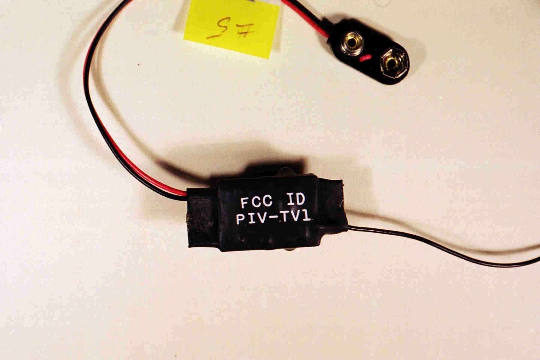
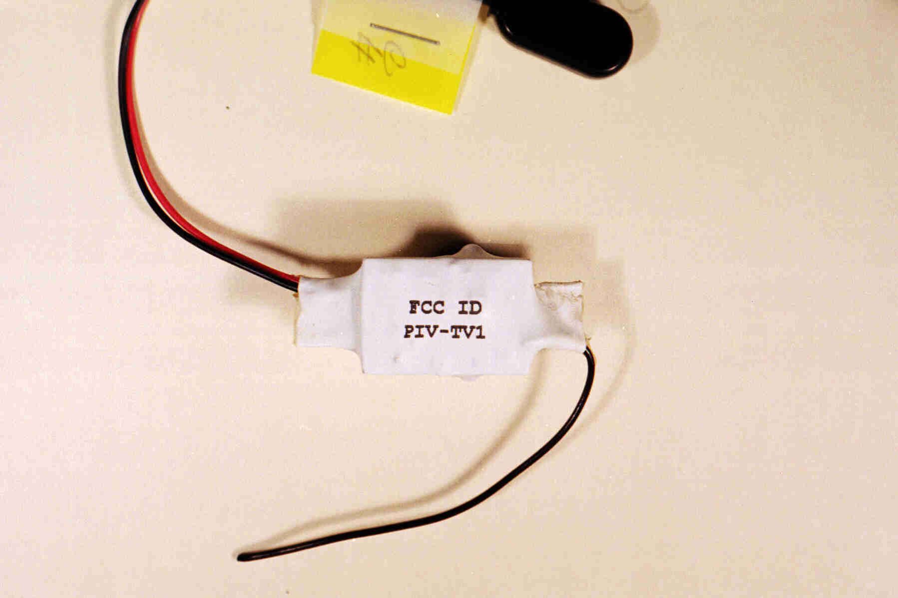
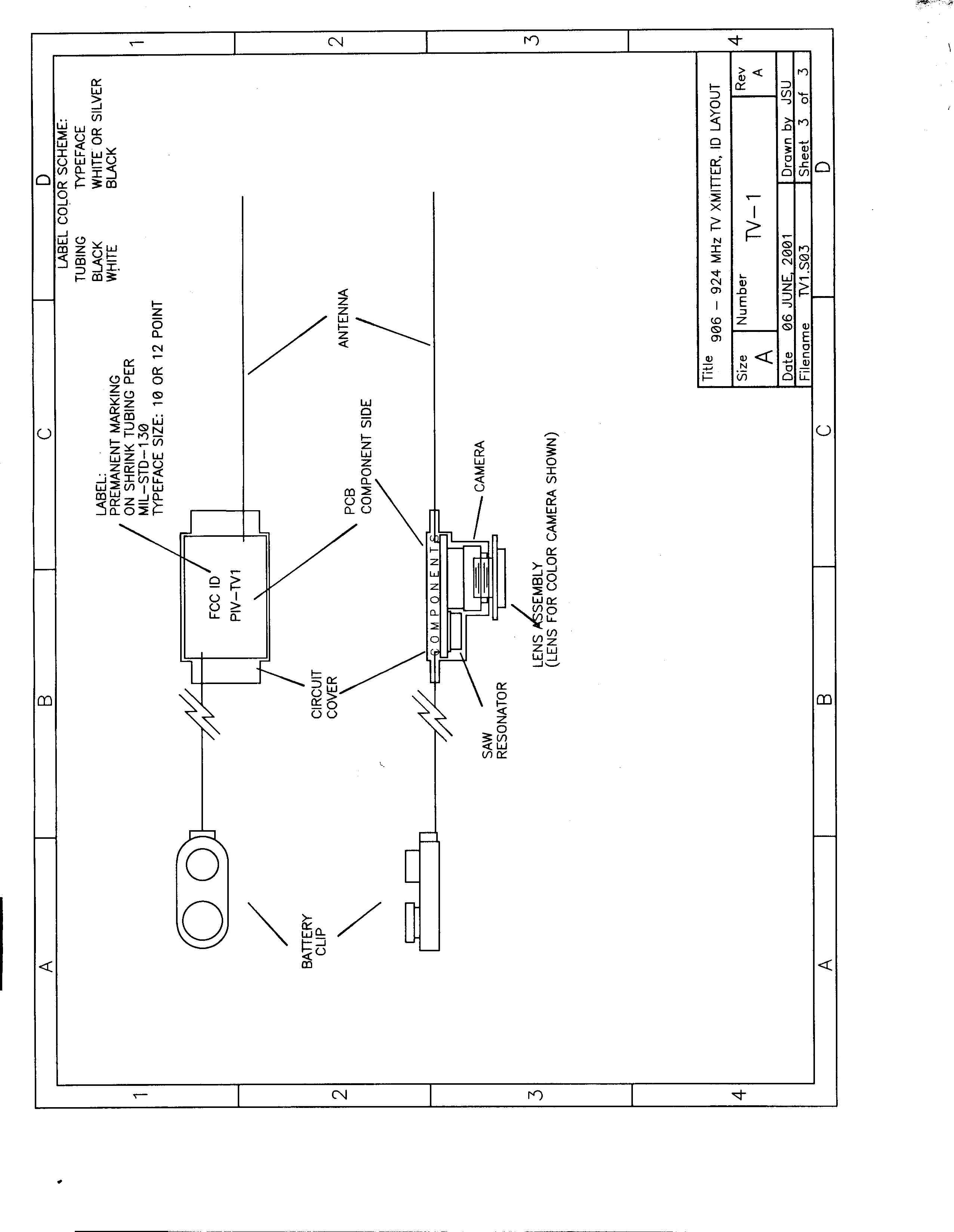
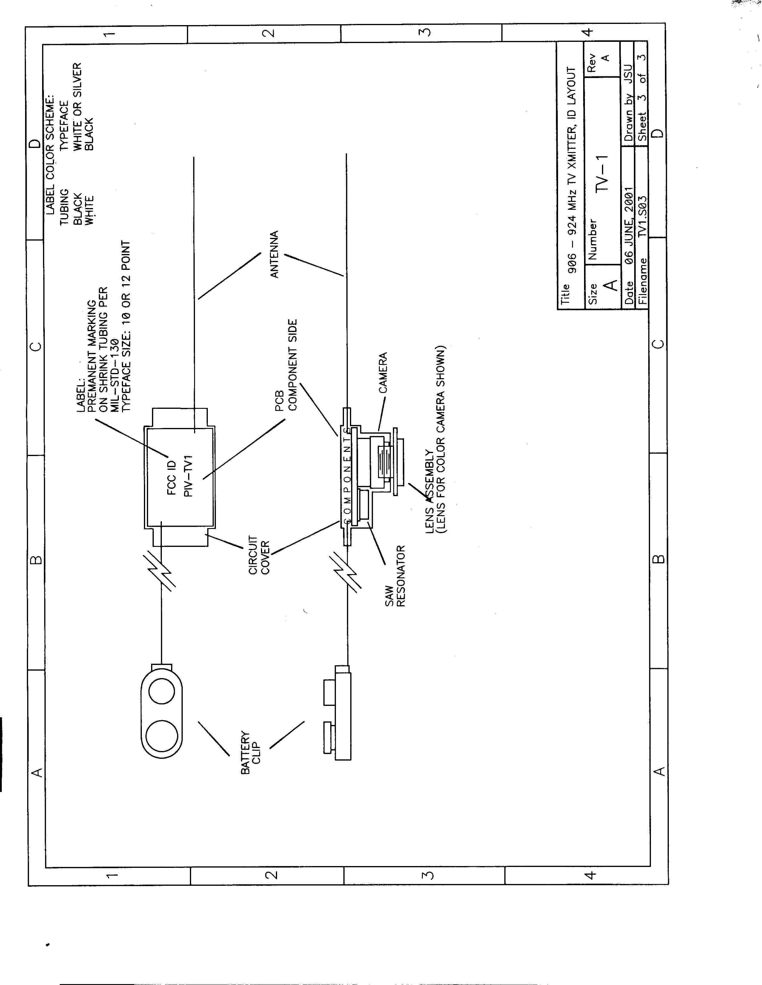
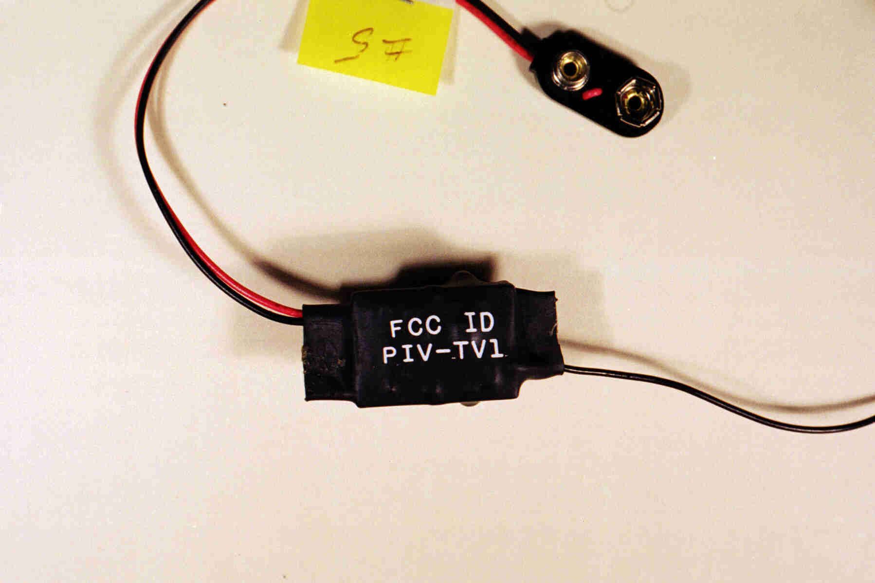
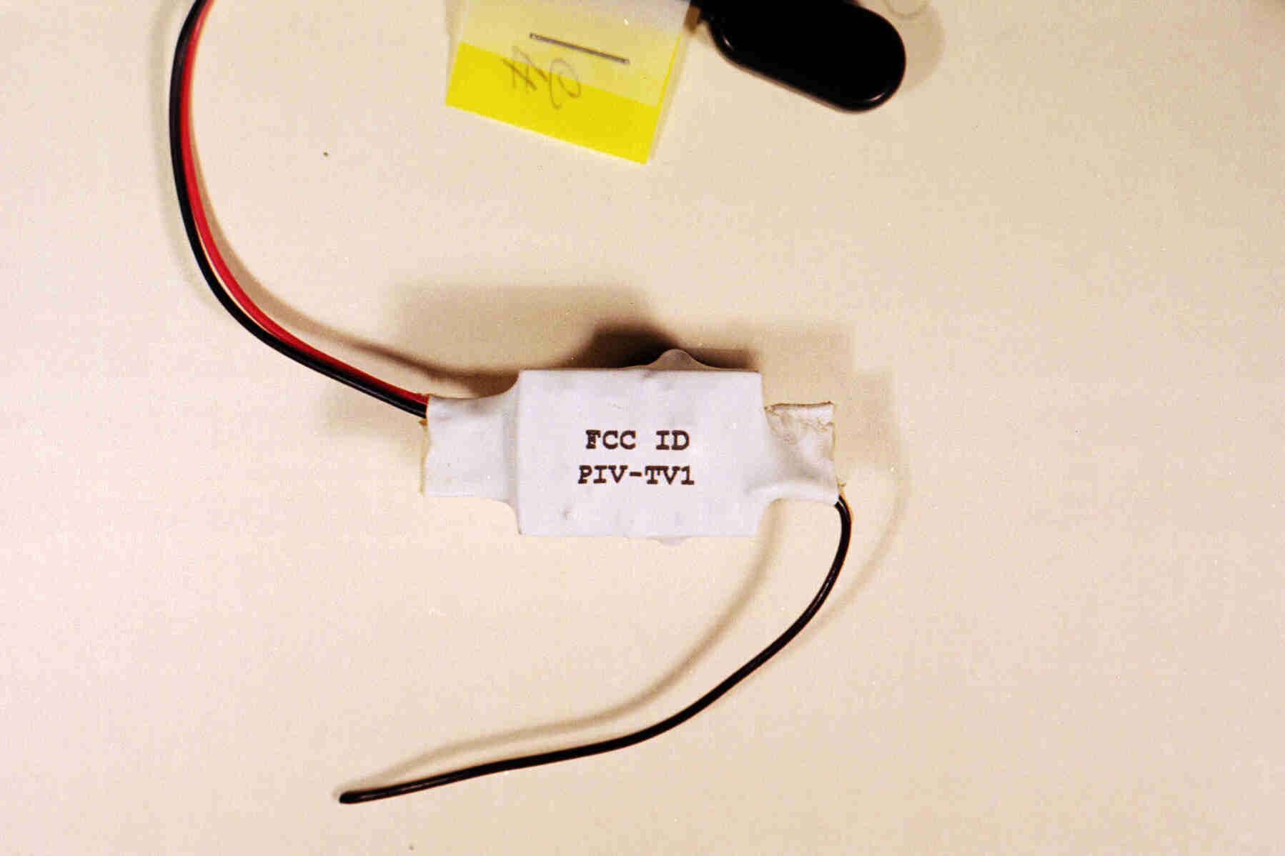
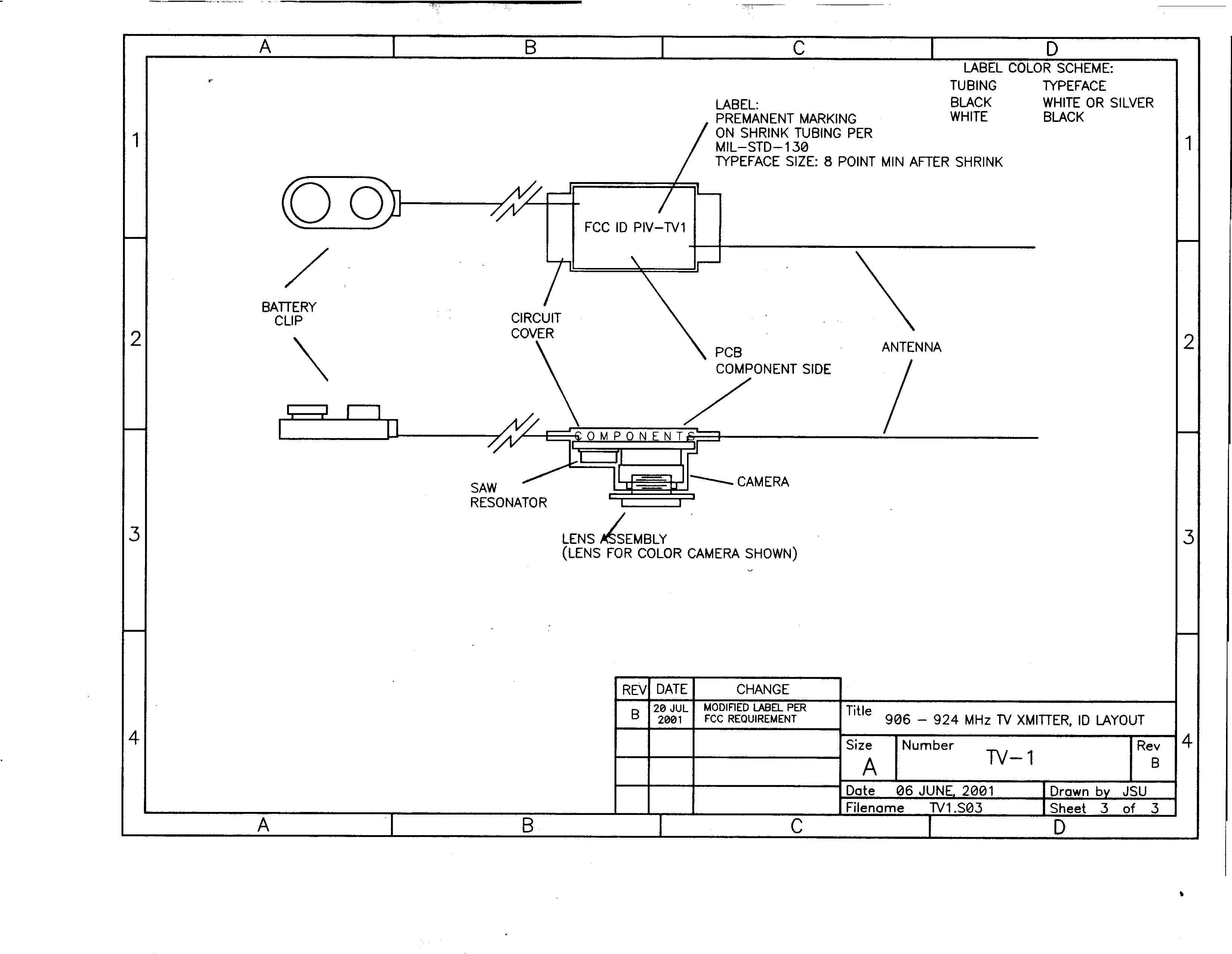
ID Label and Location Information The proposed location for the label is shown in an accompanying sketch. The proposed label will be an integral part of the shrink tubing that covers the product. The lettering will be on the reverse side from the camera location. Permanence, contrast, and durability of the lettering will be in accordance with MIL- STD-130. The typeface will be either 10 or 12 point. There is insufficient space on the product for the required labeling statement of 47CFR15.19(a)(3). In accordance with the following paragraph of the FCC Rules, this statement is prominently displayed in the manual that will be packed with the product. A copy of that manual is attached to this submission.
RF Exposure Info
RF Exposure Information The National Wireless model TV1 television transmitter can be used either as a mobile device as defined in 47CFR2.1091(b), or as a portable device as defined in 47CFR2.1093(b). This unlicensed transmitting device is categorically excluded from routine environmental evaluation for RF exposure prior to equipment authorization under 47CFR2.1091(c), as a mobile device, and under 47CFR2.1093(c), as a portable device.
Test Report
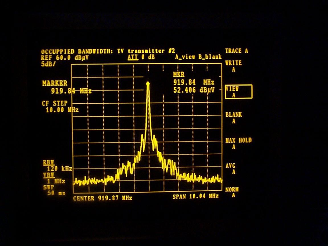
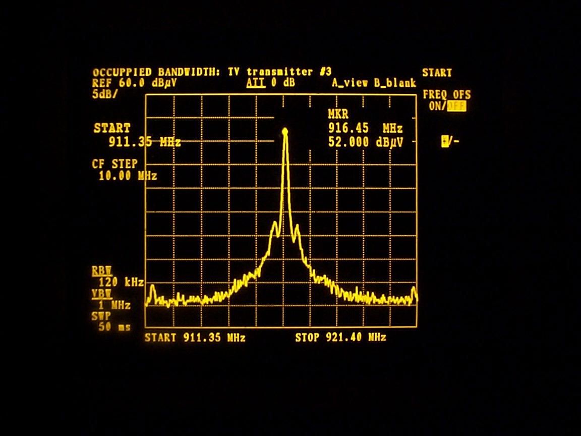
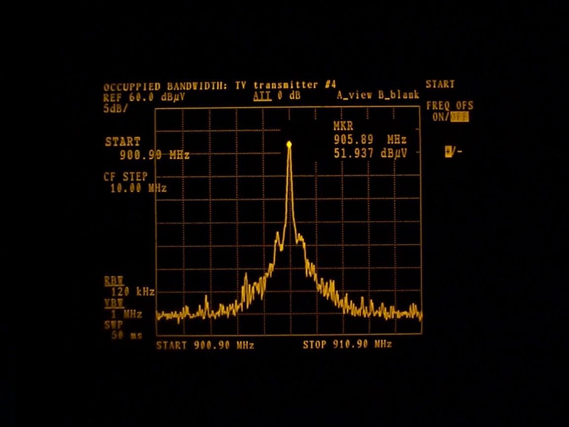
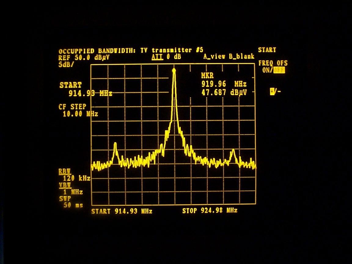
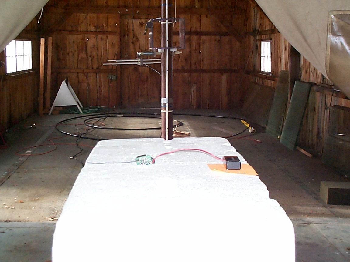
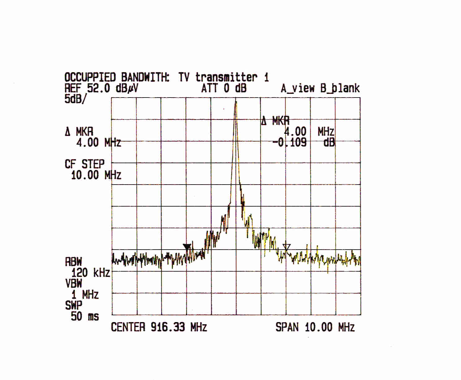
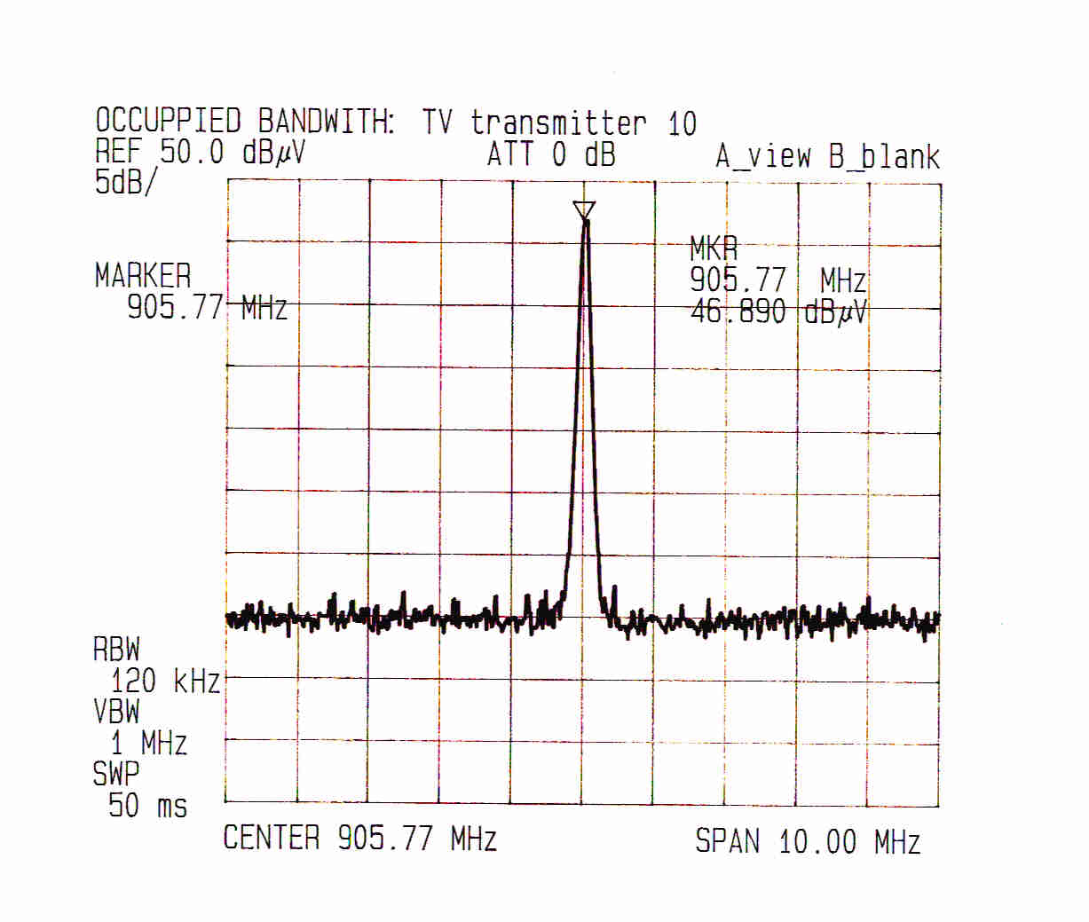
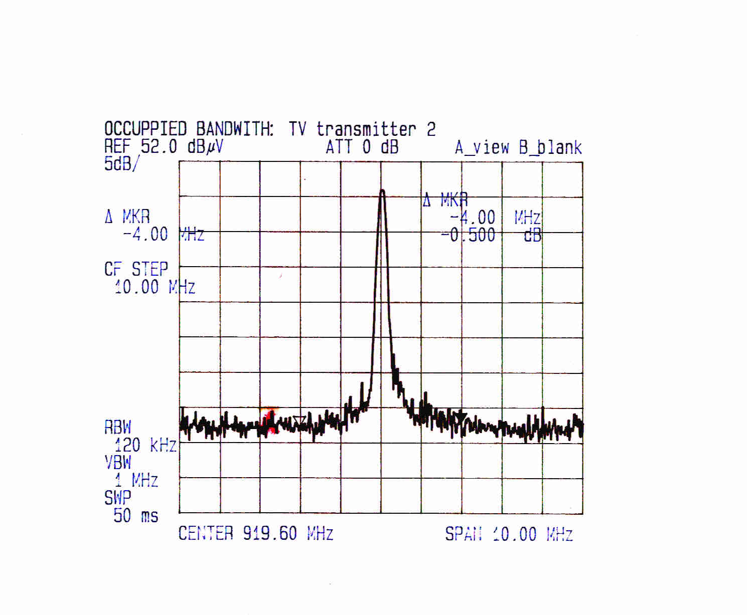
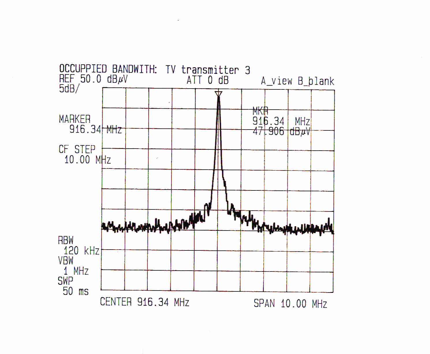
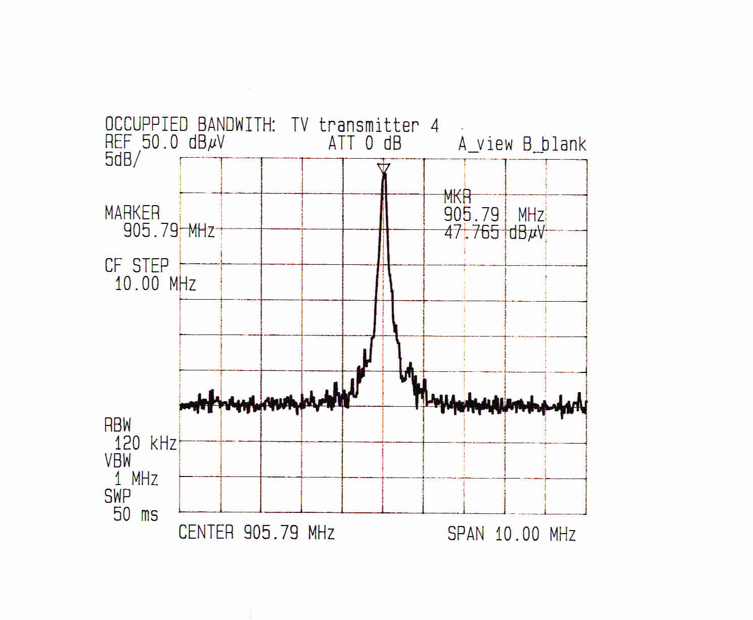
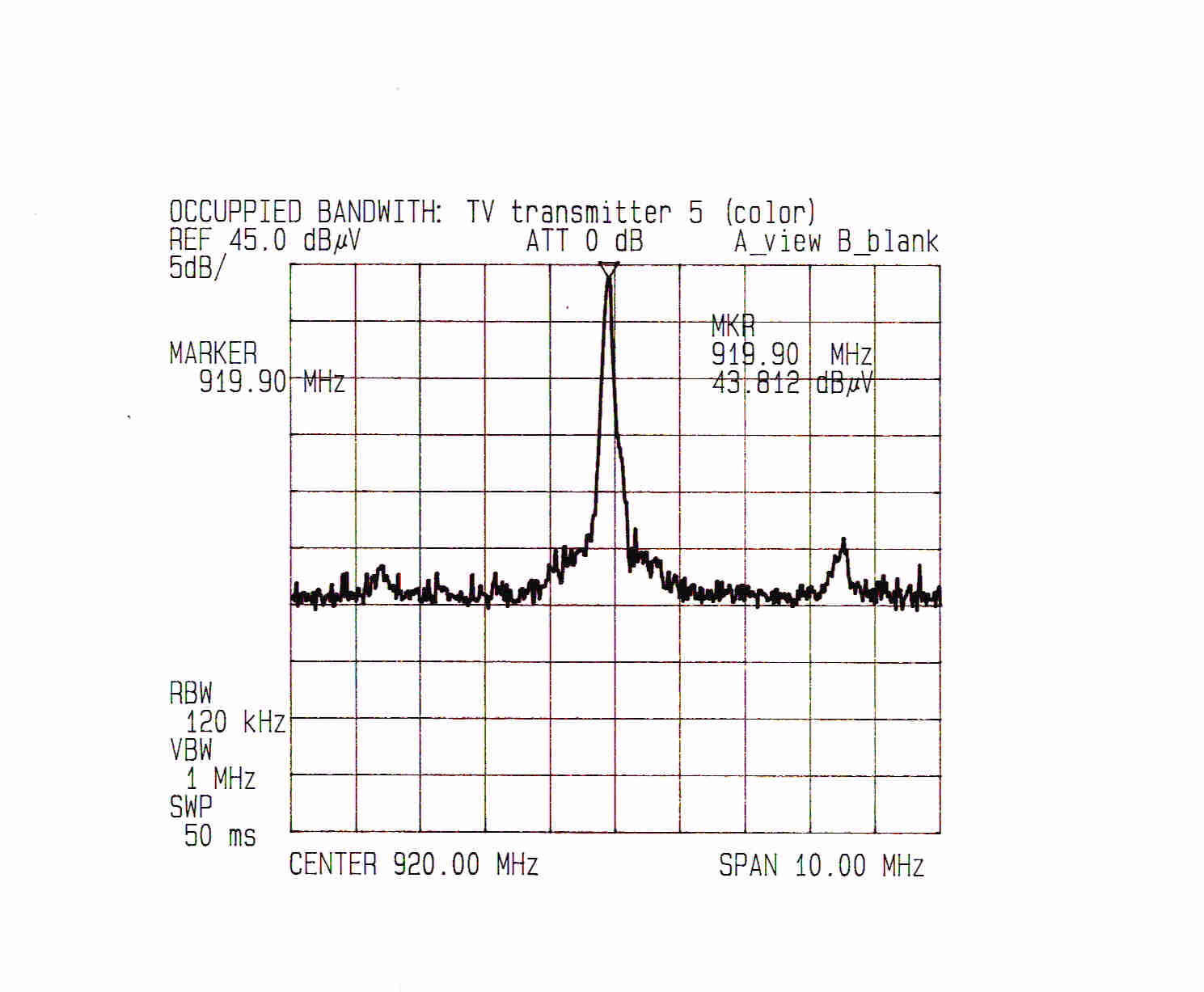
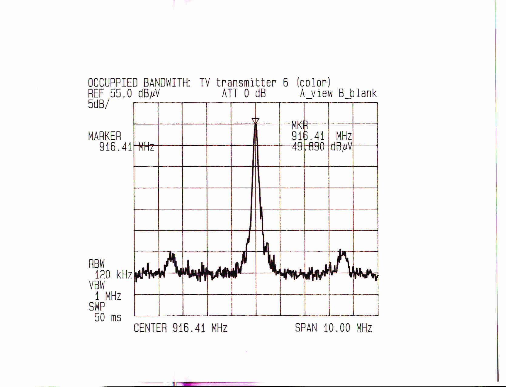
RADIATED EMISSIONS DATA USING FCC PART 15 SUBPART C LIMITS AT A 3 METER EUT TO ANTENNA DISTANCE. FILE NAME: NAT0101 EUT NAME: MINIATURE WIRELESS TV TRANSMITTERS. THE EUT IS POWERED BY AN ON-BOARD BATTERY. THERE WILL BE 10 EUT's MEASURED WITH SERIAL NUMBERS 1 TO 10. CUSTOMER REPRESENTATIVE: JIM USSAILIS SINCE ALL TRANSMITTING FREQUENCIES ARE BETWEEN 902 AND 928 MHz, FCC PART 15, SUBPART C, SECTION 15.249 ALLOWS THE TRANSMITTER A LIMIT OF 93.98 dBuV/m. OTHER EMISSIONS MUST BE BELOW 53.97 dBuV/m. THE ALLOWED BANDWIDTH IS +/- 0.5% OF THE TRANSMIT FREQUENCY. TESTED BY: STEVE PETIX ON 1/23/01 TO FCC PART 15 FOR INTENTIONALLY AND UNINTENTIONALLY RADIATING DEVICES USING THE 3 METER OPEN AREA TEST SITE. A SCHWARZBECK MODEL VHA9103 BICONICAL ANTENNA, (s/n: A) IS USED FOR 30 TO 200 MHz. AN AILTECH MODEL 96005, (s/n 1095), LOG PERIODIC ANTENNA IS USED FOR 200 TO 1000 MHz. AN ELECTROMECHANICS MODEL 3115, s/n 2498 DOUBLE RIDGE WAVEGUIDE ANTENNA IS USED FOR 1000 TO 1800 MHz. ALL MEASUREMENTS BELOW 1000 MHz USE QUASI-PEAK DETECTION. PEAK DETECTION IS USED ABOVE 1000 MHz UNLESS NOTED OTHERWISE. Prior to each measurement table, a 10 MHz wide spectrum analyzer trace was taken of the fundamental frequency. All measurements were performed while the EUT was completely operational and transmitting an image to a remote monitor. The TV transmitter antennas are laying parallel to the ground plane on top of a 1.5 meter tall foam block. The measurement antenna is horizontal, oriented in the plane of the EUT's transmitting antenna and atthe optimum height for maximum coupling. Continued on the following page. For all TV transmitters: THE 30 TO 300 MHz ANTENNA IS VERTICAL AND AT 3 METERS. FREQ. (MHz) AMPL QUASI-P dB(μ μμ μV) CABLE LOSS dB(μ μμ μV) ANTENNA FACTORS dB TOTAL FIELD dB(μ μμ μV/m) LIMIT QUASI-P dB(μ μμ μV) PASS? MARGIN dB NO SIGNIFICANT EUT GENERATED SIGNALS FOUND FOR THIS RANGE. For all TV transmitters: THE 30 TO 300 MHz ANTENNA IS HORIZONTAL AND AT 3 METERS. FREQ. (MHz) AMPL QUASI-P (dBμ μμ μV) CABLE LOSS ANTENNA FACTORS TOTAL FIELD dBμ μμ μV/m LIMIT QUASI-P (dBμ μμ μV) PASS? MARGIN (dBμ μμ μV) NO SIGNIFICANT EUT GENERATED SIGNALS FOUND FOR THIS RANGE. Using TV transmitter # 1 (Fundamental frequency of 916.5 MHz) THE 300 TO 1000 MHz ANTENNA IS VERTICAL AND AT 3 METERS. FREQ. (MHz) AMPL QUASI-P (dBμ μμ μV) CABLE LOSS ANTENNA FACTORS TOTAL FIELD dBμ μμ μV/m LIMIT QUASI-P (dBμ μμ μV) PASS? MARGIN (dBμ μμ μV) 912.00111.3130.2242.5353.79YES11.3 916.504811.3129.8989.2093.98YES4.8 920.00411.3129.5744.8853.79YES8.9 NO OTHER SIGNIFICANT EUT GENERATED SIGNALS FOUND FOR THIS RANGE. Using TV transmitter # 1 (Fundamental frequency of 916.5 MHz) THE 300 TO 1000 MHz ANTENNA IS HORIZONTAL & AT 3 METERS. FREQ. (MHz) AMPL QUASI-P dB(μ μμ μV) CABLE LOSS dB(μ μμ μV) ANTENNA FACTORS dB TOTAL FIELD dB(μ μμ μV/m) LIMIT QUASI-P dB(μ μμ μV) PASS? MARGIN dB 912.00211.3130.2243.5353.79YES10.3 916.505111.3129.8992.2093.98YES1.8 920.00511.3129.5745.8853.79YES7.9 NO OTHER SIGNIFICANT EUT GENERATED SIGNALS FOUND FOR THIS RANGE. Using TV transmitter # 2 (Fundamental frequency of 920 MHz) THE 300 TO 1000 MHz ANTENNA IS VERTICAL AND AT 3 METERS. FREQ. (MHz) AMPL QUASI-P (dBμ μμ μV) CABLE LOSS ANTENNA FACTORS TOTAL FIELD dBμ μμ μV/m LIMIT QUASI-P (dBμ μμ μV) PASS? MARGIN (dBμ μμ μV) 912.00011.3130.2241.5353.79YES12.3 920.003511.3129.5775.8893.98YES18.1 924.00111.3129.2541.5653.79YES12.2 NO OTHER SIGNIFICANT EUT GENERATED SIGNALS FOUND FOR THIS RANGE. Continued on the following page. Using TV transmitter # 2 (Fundamental frequency of 920 MHz) THE 300 TO 1000 MHz ANTENNA IS HORIZONTAL & AT 3 METERS. FREQ. (MHz) AMPL QUASI-P dB(μ μμ μV) CABLE LOSS dB(μ μμ μV) ANTENNA FACTORS dB TOTAL FIELD dB(μ μμ μV/m) LIMIT QUASI-P dB(μ μμ μV) PASS? MARGIN dB 912.00011.3130.2241.5353.79YES12.3 920.004911.3129.5789.8893.98YES4.1 924.00111.3129.2541.5653.79YES12.2 NO OTHER SIGNIFICANT EUT GENERATED SIGNALS FOUND FOR THIS RANGE. Using TV transmitter # 3 (Fundamental frequency of 916.5 MHz) THE 300 TO 1000 MHz ANTENNA IS VERTICAL AND AT 3 METERS. FREQ. (MHz) AMPL QUASI-P (dBμ μμ μV) CABLE LOSS ANTENNA FACTORS TOTAL FIELD dBμ μμ μV/m LIMIT QUASI-P (dBμ μμ μV) PASS? MARGIN (dBμ μμ μV) 916.503611.3129.8977.2093.98YES16.8 920.00011.3129.5740.8853.79YES12.9 NO OTHER SIGNIFICANT EUT GENERATED SIGNALS FOUND FOR THIS RANGE. Using TV transmitter # 3 (Fundamental frequency of 916.5 MHz) THE 300 TO 1000 MHz ANTENNA IS HORIZONTAL & AT 3 METERS. FREQ. (MHz) AMPL QUASI-P dB(μ μμ μV) CABLE LOSS dB(μ μμ μV) ANTENNA FACTORS dB TOTAL FIELD dB(μ μμ μV/m) LIMIT QUASI-P dB(μ μμ μV) PASS? MARGIN dB 904.00811.3130.8650.1753.79YES3.6 904 MHz is an ambient TV signal. 916.504711.3129.8988.2093.98YES5.8 920.00411.3129.5744.8853.79YES8.9 NO OTHER SIGNIFICANT EUT GENERATED SIGNALS FOUND FOR THIS RANGE. Because the transmitter is oriented horizontally, and to save time, measurements are only made with the receive antenna oriented horizontal. Using TV transmitter # 4 (Fundamental frequency of 906 MHz) THE 300 TO 1000 MHz ANTENNA IS HORIZONTAL & AT 3 METERS. FREQ. (MHz) AMPL QUASI-P dB(μ μμ μV) CABLE LOSS dB(μ μμ μV) ANTENNA FACTORS dB TOTAL FIELD dB(μ μμ μV/m) LIMIT QUASI-P dB(μ μμ μV) PASS? MARGIN dB 906.004811.3130.7090.0193.98YES4.0 910.00011.3130.3841.6953.79YES12.1 NO OTHER SIGNIFICANT EUT GENERATED SIGNALS FOUND FOR THIS RANGE. Continued on the following page. Using TV transmitter # 5 (Fundamental frequency of 920 MHz, color camera.) This camera has two spurious signals near the fundamental. THE 300 TO 1000 MHz ANTENNA IS HORIZONTAL & AT 3 METERS. FREQ. (MHz) AMPL QUASI-P dB(μ μμ μV) CABLE LOSS dB(μ μμ μV) ANTENNA FACTORS dB TOTAL FIELD dB(μ μμ μV/m) LIMIT QUASI-P dB(μ μμ μV) PASS? MARGIN dB 916.391211.3129.8953.2053.79YES0.6 919.874411.3129.6584.9693.98YES9.0 923.501311.3129.3353.6453.79YES0.2 NO OTHER SIGNIFICANT EUT GENERATED SIGNALS FOUND FOR THIS RANGE. Using TV transmitter # 6 (Fundamental frequency of 916.5 MHz, color camera.) This camera has two spurious signals near the funda…
Text truncated - open the document above for the full version.
Test Report
RADIATED EMISSIONS DATA FCC PART 15 SUBPART C LIMITS AT A 3 METER EUT TO ANTENNA DISTANCE. FILE NAME: NAT0101 EUT NAME: MINIATURE WIRELESS TV TRANSMITTERS. THE EUT IS POWERED BY AN ON-BOARD BATTERY. THERE WILL BE 10 EUT's MEASURED WITH SERIAL NUMBERS 1 TO 10. CUSTOMER REPRESENTATIVE: JIM USSAILIS SINCE ALL TRANSMITTING FREQUENCIES ARE BETWEEN 902 AND 928 MHz, FCC PART 15, SUBPART C, SECTION 15.249 ALLOWS THE TRANSMITTER A LIMIT OF 93.98 dBuV/m. OTHER EMISSIONS MUST BE BELOW 53.97 dBuV/m. THE ALLOWED BANDWIDTH IS +/- 0.5% OF THE TRANSMIT FREQUENCY. TESTED BY: STEVE PETIX ON 1/23/01 TO FCC PART 15 FOR INTENTIONALLY AND UNINTENTIONALLY RADIATING DEVICES THE 3 METER OPEN AREA TEST SITE. A SCHWARZBECK MODEL VHA9103 BICONICAL ANTENNA, (s/n: A) IS USED FOR 30 TO 200 MHz. AN AILTECH MODEL 96005, (s/n 1095), LOG PERIODIC ANTENNA IS USED FOR 200 TO 1000 MHz. AN ELECTROMECHANICS MODEL 3115, s/n 2498 DOUBLE RIDGE WAVEGUIDE ANTENNA IS USED FOR 1000 TO 1800 MHz. ALL MEASUREMENTS BELOW 1000 MHz USE QUASI-PEAK DETECTION AND PEAK DETECTION FOR ABOVE 1000 MHz UNLESS NOTED OTHERWISE. Prior to each measurement table, a 10 MHz wide spectrum analyzer trace was taken of the fundamental frequency. All measurements were performed while the EUT was completely operational and transmitting an image to a remote monitor. The TV transmitter antennas are laying parallel to the ground plane on top of a 1.5 meter tall foam block. The measurement antenna is oriented horizontally in the plane of the EUT's transmitting antenna and atthe optimum height for maximum coupling. Continued on the following page. For all TV transmitters: THE 30 TO 300 MHz ANTENNA IS VERTICAL AND AT 3 METERS. FREQ. (MHz) AMPL QUASI-P dB(μ μμ μV) CABLE LOSS dB(μ μμ μV) ANTENNA FACTORS dB TOTAL FIELD dB(μ μμ μV/m) LIMIT QUASI-P dB(μ μμ μV) PASS? MARGIN dB NO SIGNIFICANT EUT GENERATED SIGNALS FOUND FOR THIS RANGE. For all TV transmitters: THE 30 TO 300 MHz ANTENNA IS HORIZONTAL AND AT 3 METERS. FREQ. (MHz) AMPL QUASI-P (dBμ μμ μV) CABLE LOSS ANTENNA FACTORS TOTAL FIELD dBμ μμ μV/m LIMIT QUASI-P (dBμ μμ μV) PASS? MARGIN (dBμ μμ μV) NO SIGNIFICANT EUT GENERATED SIGNALS FOUND FOR THIS RANGE. TV transmitter # 1 (Fundamental frequency of 916.5 MHz) THE 300 TO 1000 MHz ANTENNA IS VERTICAL AND AT 3 METERS. FREQ. (MHz) AMPL QUASI-P (dBμ μμ μV) CABLE LOSS ANTENNA FACTORS TOTAL FIELD dBμ μμ μV/m LIMIT QUASI-P (dBμ μμ μV) PASS? MARGIN (dBμ μμ μV) 912.00111.3130.2242.5346YES3.5 916.504811.3129.8989.2093.98YES4.8 920.00411.3129.5744.8846YES1.1 NO OTHER SIGNIFICANT EUT GENERATED SIGNALS FOUND FOR THIS RANGE. TV transmitter # 1 (Fundamental frequency of 916.5 MHz) THE 300 TO 1000 MHz ANTENNA IS HORIZONTAL & AT 3 METERS. FREQ. (MHz) AMPL QUASI-P dB(μ μμ μV) CABLE LOSS dB(μ μμ μV) ANTENNA FACTORS dB TOTAL FIELD dB(μ μμ μV/m) LIMIT QUASI-P dB(μ μμ μV) PASS? MARGIN dB 912.00211.3130.2243.5346YES2.5 916.505111.3129.8992.2093.98YES1.8 920.00511.3129.5745.8846YES0.1 NO OTHER SIGNIFICANT EUT GENERATED SIGNALS FOUND FOR THIS RANGE. TV transmitter # 2 (Fundamental frequency of 920 MHz) THE 300 TO 1000 MHz ANTENNA IS VERTICAL AND AT 3 METERS. FREQ. (MHz) AMPL QUASI-P (dBμ μμ μV) CABLE LOSS ANTENNA FACTORS TOTAL FIELD dBμ μμ μV/m LIMIT QUASI-P (dBμ μμ μV) PASS? MARGIN (dBμ μμ μV) 912.00011.3130.2241.5346YES4.5 920.003511.3129.5775.8893.98YES18.1 924.00111.3129.2541.5646YES4.4 NO OTHER SIGNIFICANT EUT GENERATED SIGNALS FOUND FOR THIS RANGE. Continued on the following page. TV transmitter # 2 (Fundamental frequency of 920 MHz) THE 300 TO 1000 MHz ANTENNA IS HORIZONTAL & AT 3 METERS. FREQ. (MHz) AMPL QUASI-P dB(μ μμ μV) CABLE LOSS dB(μ μμ μV) ANTENNA FACTORS dB TOTAL FIELD dB(μ μμ μV/m) LIMIT QUASI-P dB(μ μμ μV) PASS? MARGIN dB 912.00011.3130.2241.5346YES4.5 920.004911.3129.5789.8893.98YES4.1 924.00111.3129.2541.5646YES4.4 NO OTHER SIGNIFICANT EUT GENERATED SIGNALS FOUND FOR THIS RANGE. TV transmitter # 3 (Fundamental frequency of 916.5 MHz) THE 300 TO 1000 MHz ANTENNA IS VERTICAL AND AT 3 METERS. FREQ. (MHz) AMPL QUASI-P (dBμ μμ μV) CABLE LOSS ANTENNA FACTORS TOTAL FIELD dBμ μμ μV/m LIMIT QUASI-P (dBμ μμ μV) PASS? MARGIN (dBμ μμ μV) 916.503611.3129.8977.2093.98YES16.8 920.00011.3129.5740.8846YES5.1 NO OTHER SIGNIFICANT EUT GENERATED SIGNALS FOUND FOR THIS RANGE. TV transmitter # 3 (Fundamental frequency of 916.5 MHz) THE 300 TO 1000 MHz ANTENNA IS HORIZONTAL & AT 3 METERS. FREQ. (MHz) AMPL QUASI-P dB(μ μμ μV) CABLE LOSS dB(μ μμ μV) ANTENNA FACTORS dB TOTAL FIELD dB(μ μμ μV/m) LIMIT QUASI-P dB(μ μμ μV) PASS? MARGIN dB 904.00811.3130.8650.1746NO4.2 904 MHz is an ambient TV signal. 916.504711.3129.8988.2093.98YES5.8 920.00411.3129.5744.8846YES1.1 NO OTHER SIGNIFICANT EUT GENERATED SIGNALS FOUND FOR THIS RANGE. Because the transmitter is oriented horizontally, and to save time, measurements are only made with the receive antenna oriented horizontally. TV transmitter # 4 (Fundamental frequency of 906 MHz) THE 300 TO 1000 MHz ANTENNA IS HORIZONTAL & AT 3 METERS. FREQ. (MHz) AMPL QUASI-P dB(μ μμ μV) CABLE LOSS dB(μ μμ μV) ANTENNA FACTORS dB TOTAL FIELD dB(μ μμ μV/m) LIMIT QUASI-P dB(μ μμ μV) PASS? MARGIN dB 906.004811.3130.7090.0193.98YES4.0 910.00011.3130.3841.6946YES4.3 NO OTHER SIGNIFICANT EUT GENERATED SIGNALS FOUND FOR THIS RANGE. Continued on the following page. TV transmitter # 5 (Fundamental frequency of 920 MHz, color camera.) This camera has two spurious signals near the fundamental. THE 300 TO 1000 MHz ANTENNA IS HORIZONTAL & AT 3 METERS. FREQ. (MHz) AMPL QUASI-P dB(μ μμ μV) CABLE LOSS dB(μ μμ μV) ANTENNA FACTORS dB TOTAL FIELD dB(μ μμ μV/m) LIMIT QUASI-P dB(μ μμ μV) PASS? MARGIN dB 916.391211.3129.8953.2046NO7.2 919.874411.3129.6584.9693.98YES9.0 923.501311.3129.3353.6446NO7.6 NO OTHER SIGNIFICANT EUT GENERATED SIGNALS FOUND FOR THIS RANGE. TV transmitter # 6 (Fundamental frequency of 916.5 MHz, color camera.) This camera has two spurious signals near the fundamental. THE 300 TO 1000 MHz ANTENNA IS HORIZONTAL & AT 3 METERS. FREQ. (MHz) AMPL QUASI-P dB(μ μμ μV) CABLE LOSS dB(μ…
Text truncated - open the document above for the full version.
Test Report
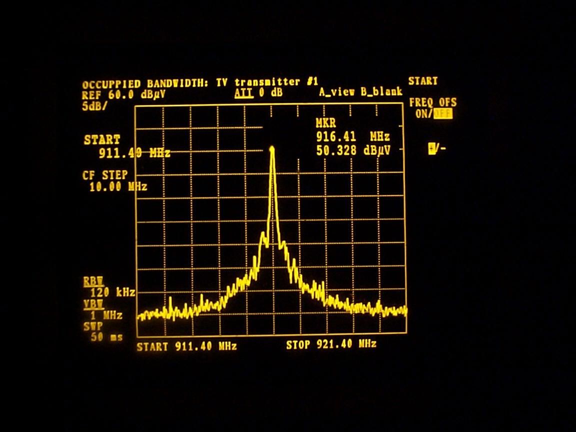
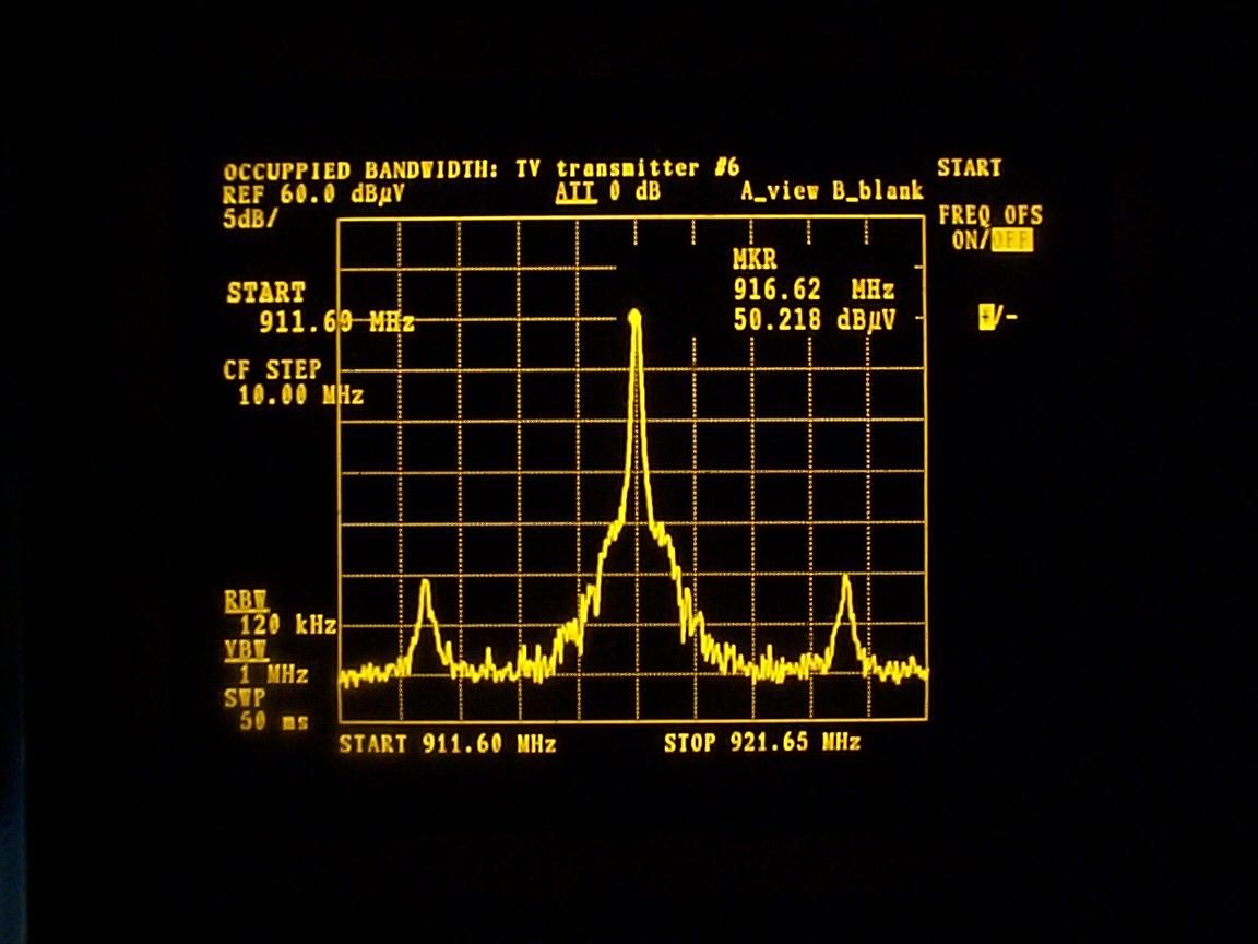
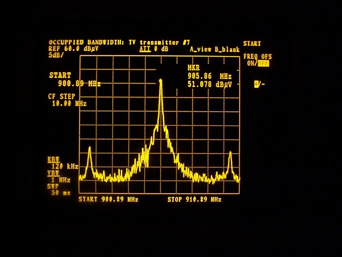
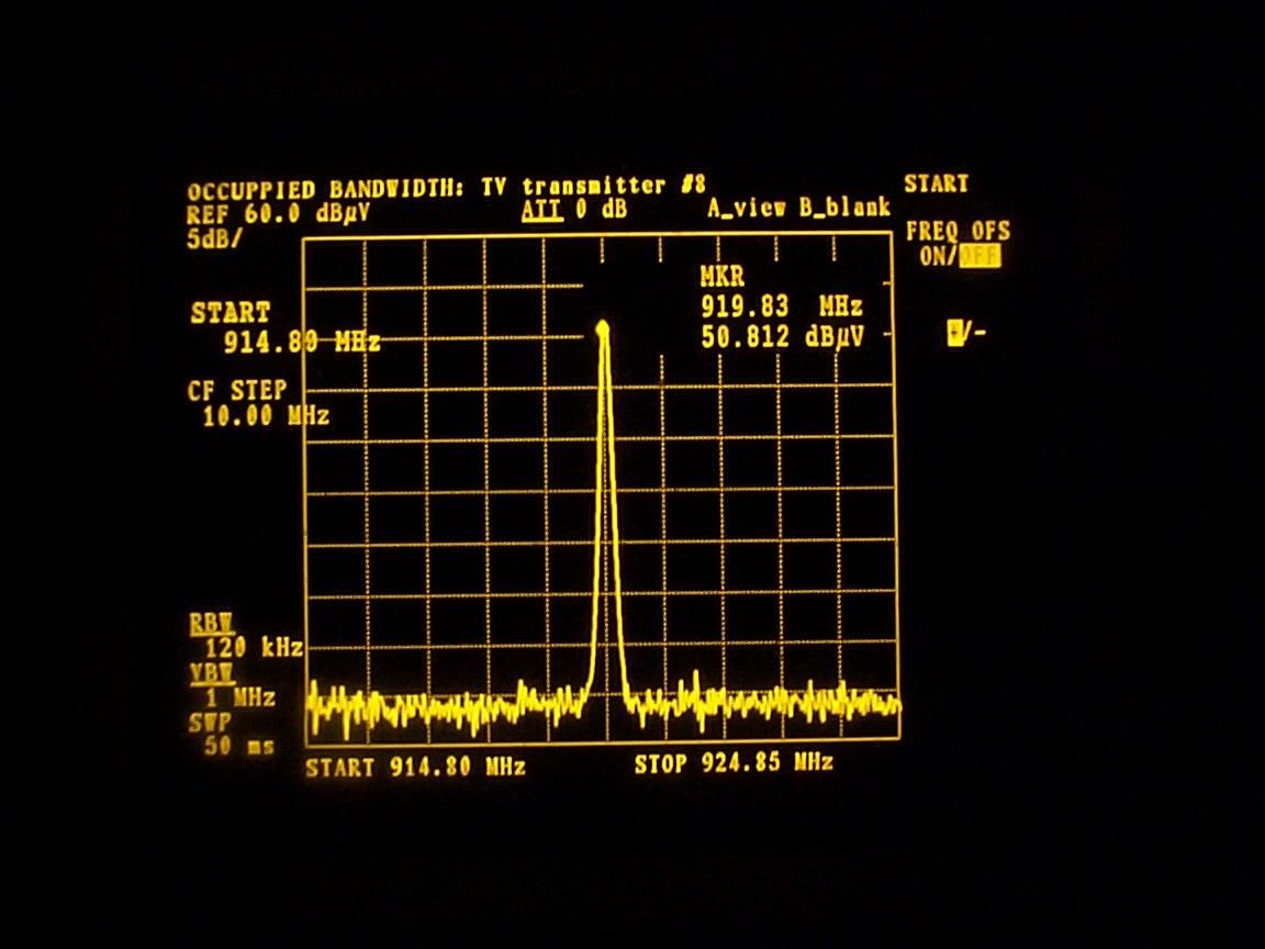
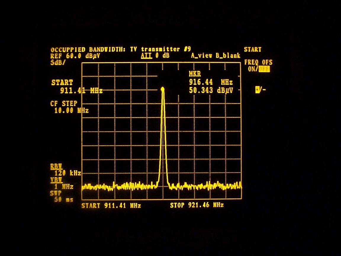
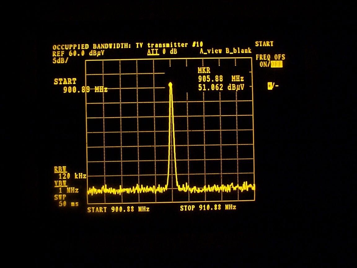
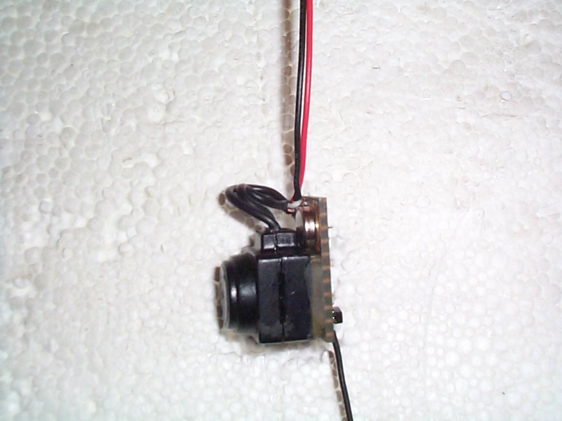
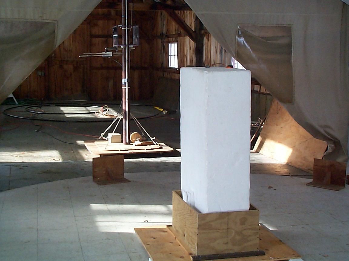
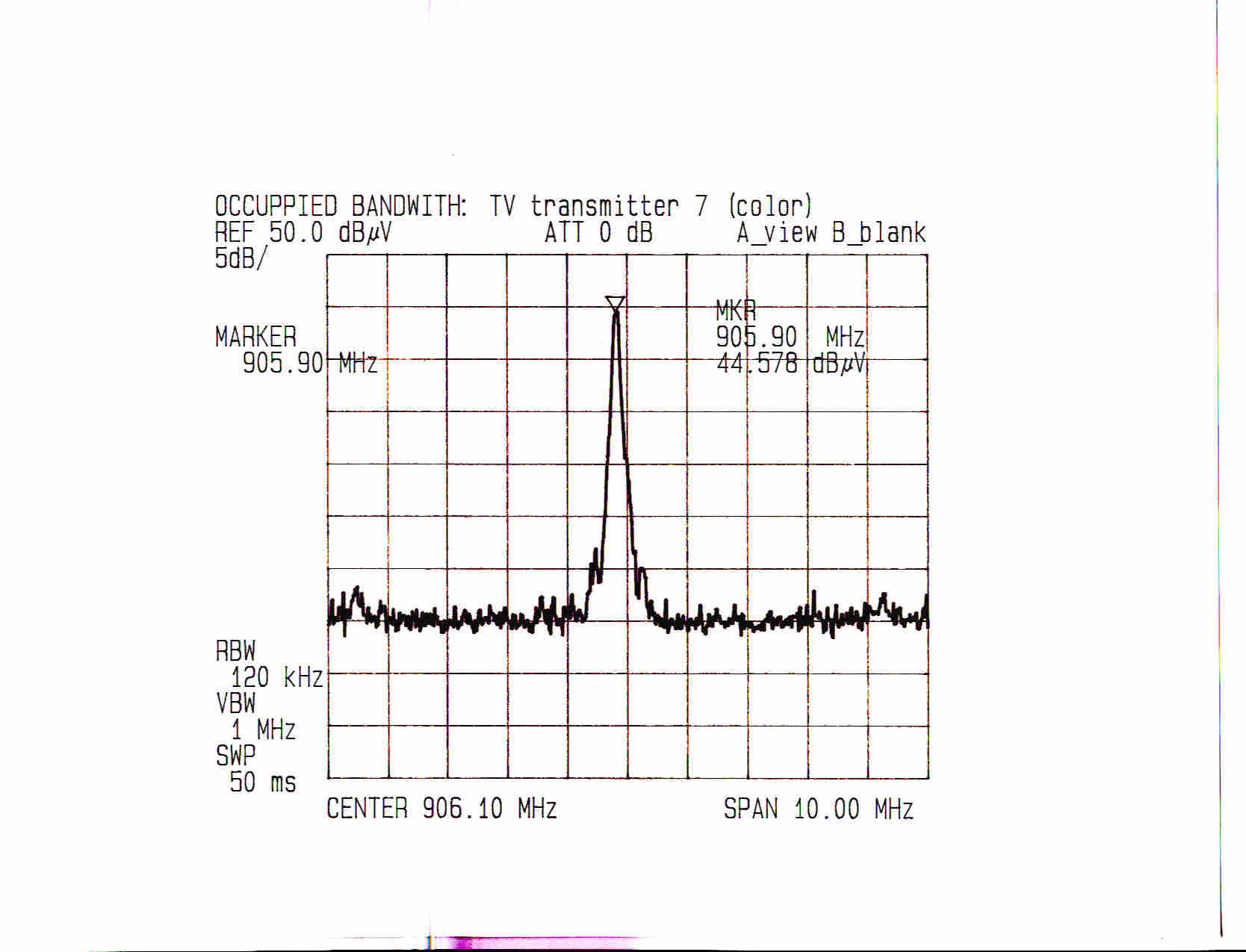
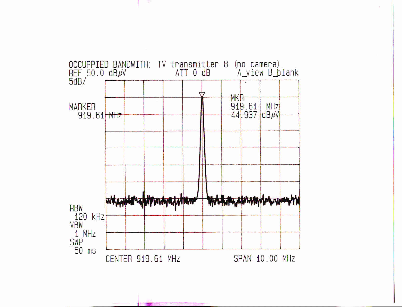
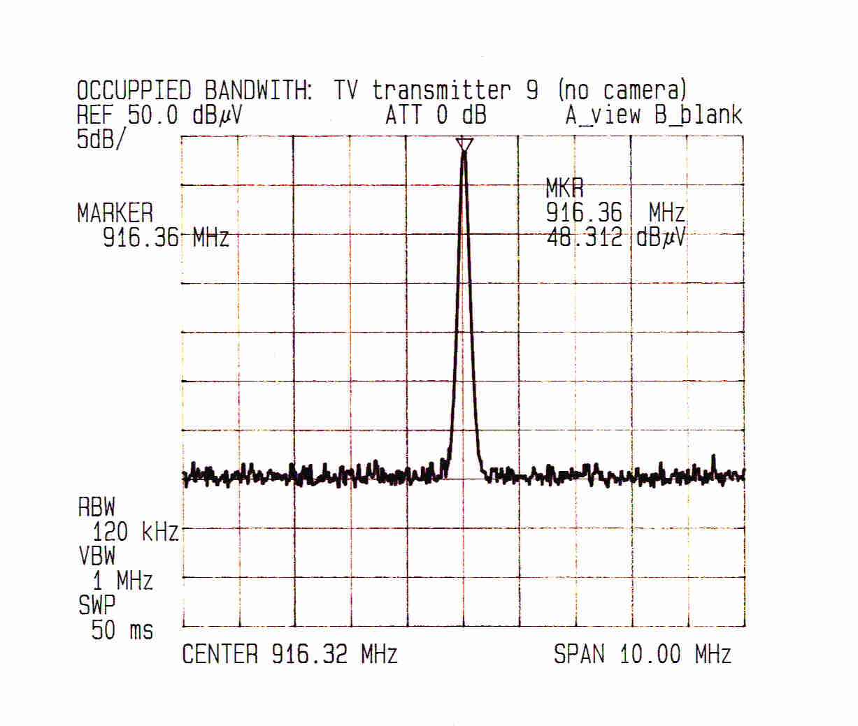
RADIATED EMISSIONS DATA USING FCC PART 15 SUBPART C LIMITS AT 3 METER AND 1 METER EUT TO ANTENNA DISTANCES. FILE NAME: NAT0102 EUT NAME: MINIATURE WIRELESS TV TRANSMITTERS. THE EUTs ARE POWERED BY 9vdc BATTERIES (1 battery/camera). THERE WILL BE TEN UNITS MEASURED. THEY ARE LABELED 1 TO 10. CUSTOMER REPRESENTATIVE: JIM USSAILIS TESTED BY: STEVE PETIX ON 8/28/01 TO FCC PART 15 FOR INTENTIONALLY AND UNINTENTIONALLY RADIATING DEVICES USING THE 3 METER OPEN AREA TEST SITE FOR 30 TO 1000 MHz AND A 1 METER DISTANCE IN FRONT OF THE SPECTRUM ANALYZER. A SCHWARZBECK MODEL VHA9103 BICONICAL ANTENNA, (s/n: A) IS USED FOR 30 TO 200 MHz. AN AILTECH MODEL 96005, (s/n 1095), LOG PERIODIC ANTENNA IS USED FOR 200 TO 1000 MHz. AN ELECTROMECHANICS MODEL 3115, s/n 2498 DOUBLE RIDGE WAVEGUIDE ANTENNA IS USED FOR 1000 TO 18,000 MHz. ALL MEASUREMENTS BELOW 1000 MHz USE QUASI-PEAK DETECTION. FOR ABOVE 1000 MHz, PEAK AND AVERAGE DETECTION ARE USED. SINCE ALL TRANSMITTING FREQUENCIES USED BY THESE TV TRANSMITTERS ARE BETWEEN 906 AND 920 MHz, FCC PART 15, SUBPART C, SECTION 15.249 ALLOWS THE TRANSMITTER FUNDAMENTAL FREQUENCIES A LIMIT OF 93.98 dBuV/m. HARMONICS MUST BE BELOW 53.98 dBuV/m. THE ALLOWED BANDWIDTH IS +/- 0.5% OF THE TRANSMIT FREQUENCY, APPROXIMATELY 4 MHz. A 10MHz-wide spectrum analyzer trace was taken of the fundamental frequency for all ten TV transmitters. The traces demonstrates the bandwidth compliance. All measurements were performed while the EUT was completely operational and transmitting an image to a remote monitor fifteen meters distant. The ten EUT samples represent potential configurations of black & white, color, and stand-alone (no camera) transmitting sections at different fundamental transmitting frequencies. Where used, the color-phasing signals are treated as fundamental signals. ` The TV transmitter antennas are orientated vertically. The transmitters are fixed into a slot cut in a foam block with the device's center 1.5 meters above the ground plane. The measurement antenna is vertical and adjusted to the optimum height for maximum coupling. Measurements with the transmit antenna vertical and the receive antenna horizontal were not performed because the EUTs have neglible dimensions compared to the 1/4 wave whip antenna and power lead. The antenna and power lead with 9VDC battery attached were stretched in a linear fashion as seen in the photographs. To better control fundamental and spurious emissions, the output capacitor, C10 was changed from 5.0 pfd to 5.6 pfd. This reduced the fundamental and harmonic signal strengths approximately 2 to 3 decibels. Continued on the following page. For all TV transmitters: THE 30 TO 300 MHz ANTENNA IS VERTICAL AND AT 3 METERS. FREQ. (MHz) AMPL QUASI-P dB(μ μμ μV) CABLE LOSS dB(μ μμ μV) ANTENNA FACTORS dB TOTAL FIELD dB(μ μμ μV/m) LIMIT QUASI-P dB(μ μμ μV) PASS? MARGIN dB NO SIGNIFICANT EUT GENERATED SIGNALS FOUND FOR THIS RANGE. FUNDAMENTAL FREQUENCY MEASUREMENTS: TV transmitter # 1 (Fundamental frequency of 916.5 MHz, Black & White camera) THE 300 TO 1000 MHz ANTENNA IS VERTICAL AND AT 3 METERS. FREQ. (MHz) AMPL QUASI-P (dBμ μμ μV) CABLE LOSS ANTENNA FACTORS TOTAL FIELD dBμ μμ μV/m LIMIT QUASI-P (dBμ μμ μV) PASS? MARGIN (dBμ μμ μV) 916.405011.3129.8991.2093.98YES2.8 NO OTHER SIGNIFICANT EUT GENERATED SIGNALS FOUND FOR THIS RANGE. TV transmitter # 2 (Fundamental frequency of 920 MHz, Black & White camera) THE 300 TO 1000 MHz ANTENNA IS VERTICAL AND AT 3 METERS. FREQ. (MHz) AMPL QUASI-P dB(μ μμ μV) CABLE LOSS dB(μ μμ μV) ANTENNA FACTORS dB TOTAL FIELD dB(μ μμ μV/m) LIMIT QUASI-P dB(μ μμ μV) PASS? MARGIN dB 920.005211.3129.5792.8893.98YES1.1 NO OTHER SIGNIFICANT EUT GENERATED SIGNALS FOUND FOR THIS RANGE. TV transmitter # 3 (Fundamental frequency of 916.5 MHz, Black & White camera.) THE 300 TO 1000 MHz ANTENNA IS VERTICAL AND AT 3 METERS. FREQ. (MHz) AMPL QUASI-P (dBμ μμ μV) CABLE LOSS ANTENNA FACTORS TOTAL FIELD dBμ μμ μV/m LIMIT QUASI-P (dBμ μμ μV) PASS? MARGIN (dBμ μμ μV) 916.455211.3129.8993.2093.98YES0.8 NO OTHER SIGNIFICANT EUT GENERATED SIGNALS FOUND FOR THIS RANGE. Continued on the following page. FUNDAMENTAL FREQUENCY MEASUREMENTS: Using TV transmitter # 4 (Fundamental frequency of 906 MHz, Black & White Camera) THE 300 TO 1000 MHz ANTENNA IS VERTICAL AND AT 3 METERS. FREQ. (MHz) AMPL QUASI-P dB(μ μμ μV) CABLE LOSS dB(μ μμ μV) ANTENNA FACTORS dB TOTAL FIELD dB(μ μμ μV/m) LIMIT QUASI-P dB(μ μμ μV) PASS? MARGIN dB 905.895111.3130.7893.0993.98YES0.9 NO OTHER SIGNIFICANT EUT GENERATED SIGNALS FOUND FOR THIS RANGE. Using TV transmitter # 5 (Fundamental frequency of 920 MHz, color camera.) THE 300 TO 1000 MHz ANTENNA IS VERTICAL AND AT 3 METERS. FREQ. (MHz) AMPL QUASI-P dB(μ μμ μV) CABLE LOSS dB(μ μμ μV) ANTENNA FACTORS dB TOTAL FIELD dB(μ μμ μV/m) LIMIT QUASI-P dB(μ μμ μV) PASS? MARGIN dB 916.392411.3129.8965.2093.98YES28.8 919.874711.3129.6587.9693.98YES6.0 923.502011.3129.3360.6493.98YES33.3 NO OTHER SIGNIFICANT EUT GENERATED SIGNALS FOUND FOR THIS RANGE. TV transmitter # 6 (Fundamental frequency of 916.5 MHz, color camera.) THE 300 TO 1000 MHz ANTENNA IS VERTICAL & AT 3 METERS. FREQ. (MHz) AMPL QUASI-P dB(μ μμ μV) CABLE LOSS dB(μ μμ μV) ANTENNA FACTORS dB TOTAL FIELD dB(μ μμ μV/m) LIMIT QUASI-P dB(μ μμ μV) PASS? MARGIN dB 912.432411.3130.2265.5393.98YES28.5 916.625011.3129.8991.2093.98YES2.8 920.232511.3129.5765.8893.98YES28.1 NO OTHER SIGNIFICANT EUT GENERATED SIGNALS FOUND FOR THIS RANGE. Using TV transmitter # 7 (Fundamental frequency of 906 MHz, color camera.) THE 300 TO 1000 MHz ANTENNA IS VERTICAL & AT 3 METERS. FREQ. (MHz) AMPL QUASI-P dB(μ μμ μV) CABLE LOSS dB(μ μμ μV) ANTENNA FACTORS dB TOTAL FIELD dB(μ μμ μV/m) LIMIT QUASI-P dB(μ μμ μV) PASS? MARGIN dB 901.492711.313…
Text truncated - open the document above for the full version.
Contact Information
Applicant
James S Ussailis(President)
Technical Contact
National Wireless, Inc.James S Ussailis
[email protected]413-586-5111
Suite 1G3 · Florence, Massachusetts · United States
Non-Technical Contact
National Wireless, Inc.James S Ussailis
[email protected]413-586-5111
Test Firm
Global Certification Laboratory LtdSteve Petix
Technical Specifications
| # | Rule Parts | Frequency Range | Power Output | Tolerance |
|---|---|---|---|---|
| 1 | 15C | 906 MHz - 924 MHz | - | % |