PIYB5074-04A4R6V TRUCK
Mattel Asia Pacific Sourcing Ltd.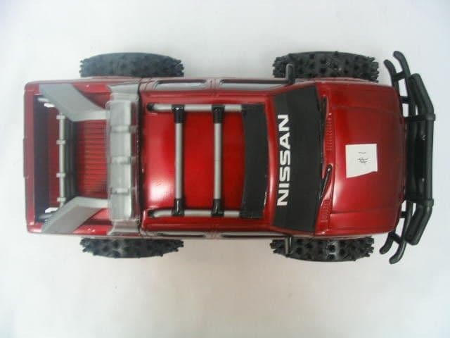
Click to zoom
Application Details
- Equipment Class
- CRR - Superregenerative Receiver
- Date of Grant
- Jun 30, 2004
- Application Purpose
- Original Equipment
- Date of Application
- Jun 30, 2004
- Equipment Note
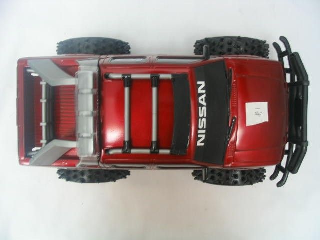
- 6V TRUCK
- Frequency Range
- 49.86000000 - 49.86000000
- Country
- Hong Kong
Documents & Files

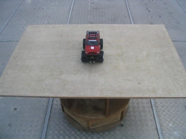
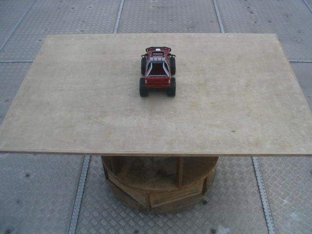
Document Text
Text extracted from the exhibit documents filed with the FCC. Open a document above to read the original.
Users Manual
00007-1761G1 Keep these instructions for future reference: they contain important information. IMPORTANT: Please read all “Consumer Information” before operating your vehicle. Guardar estas instrucciones para futura referencia, ya que contienen información de importancia. IMPORTANTE: Leer toda la información antes de usar su vehículo. Conserver ces instructions pour y référer en cas de besoin. IMPORTANT: Lire tous les renseignements pour consommateurs avant de faire fonctionner le véhicule. 6.0V R/C 6.0V R/C CAUTION:Surfaces may become hot and cause burns if electronics get wet. Do not operate vehicle through water or snow. ❶ ❷ ❸ ❹ PRECAUCIÓN:Si las piezas electrónicas se mojan, es posible que las superficies se calienten y causen quemaduras. No usar el vehículo en agua ni nieve. MISE EN GARDE: Les surfaces peuvent devenir chaudes et causer des brûlures si les composantes électroniques sont mouillées. Ne pas faire rouler ce véhicule sur des surfaces mouillées ou enneigées. I. II. A B C ❶ ❷ ❸ ❹ ❶ ❷ ❸ ❶ ❷ ❸ I. CONTENTS Vehicle Transmitter Power Clip (if supplied) CHASSIS Your vehicle’s chassis will look like A, B, C or D, depending on the vehicle’s design. ❶ON/OFF Switch ❷Battery Latch ❸Steering Adjuster ❹Gear Selector (if applicable) Refer to label on transmitter and vehicle for frequency. Do not race vehicles with the same frequency. II. VEHICLE OPERATION ❶Forward ❷Reverse ❸Left ❹Right I. CONTENIDO Vehículo Transmisor Clip de pilas (si viene incluido) CHASÍS El chasís del vehículo se verá como A, B, C ó D, según el diseño del vehículo. ❶Interruptor de ENCENDIDO/APAGADO ❷Seguro de la batería ❸Ajustador de viraje ❹Selector de velocidades (si aplica) Consultar la etiqueta del transmisor y vehículo para información sobre la frecuencia. No jugar a las carreras con vehículos de la misma frecuencia. II. FUNCIONAMIENTO DEL VEHÍCULO ❶Marcha adelante ❷Reversa ❸Izquierda ❹Derecha I. CONTIENT Véhicule Émetteur Bloc puissance (si fourni) CHÂSSIS Le châssis de votre véhicule ressemblera à l’illustration A, B, C ou D, selon le modèle. ❶Interrupteur ON/OFF ❷Verrou du compartiment des piles ❸Dispositif de réglage de la direction ❹Sélecteur de vitesses (si approprié) Se référer aux instructions fournies sur l’émetteur et le véhicule pour choisir la fréquence. Ne pas faire de course de vitesse entre véhicules télécommandés sur la même fréquence. II. FONCTIONNEMENT DU VÉHICULE ❶Marche avant ❷Marche arrière ❸Virage à gauche ❹Virage à droite D ❶ ❷ ❸ ❹ IV. III. A B III. POWER SYSTEMS Please check the package for the specific power system for this vehicle: Some vehicles use the Tyco® R/C 6.0V Jet Turbo® rechargeable NiCd Battery Pack & Charger. Some vehicles use 4 AA batteries (installed in a special Power Clip) OR the Tyco® R/C 6.0V Jet Turbo® rechargeable NiCd Battery Pack & Charger. For detailed information regarding NiCd battery charging and safety, please follow the specific instructions that came with your battery pack and charger. A. POWER CLIP – INSTALLATION OF 4 AA BATTERIES Use a screwdriver (not included) to unscrew Power Clip cover screw. Remove cover. Insert 4 AA batteries, with polarity (+/-) as shown inside Power Clip. Replace cover. B. VEHICLE BATTERY INSTALLATION These instructions apply to both the 4 AA Power Clip and the 6.0V Jet Turbo® rechargeable NiCd Battery Pack. They are installed in the vehicle the same way. 1. Rotate battery latch to open position. 2. Insert the Power Clip (or rechargeable NiCd battery pack) into battery compartment and slide it away from latch. 3. Make sure Power Clip (or rechargeable NiCd battery pack) snaps securely in place. Rotate latch to locked position. 4. To remove: turn latch, slide toward latch and lift out. IV. TRANSMITTERS Your vehicle will use one of the 3 transmitters shown. It is equipped with a special automatic-on battery-saving feature. Just turn your vehicle ON. Then push either control and you will be able to run and control your vehicle. A. TRANSMITTER 1 – BATTERY INSTALLATION 1. Open battery cover as shown. 2. Install 2 AA alkaline batteries with polarity (+/-) as shown inside battery compartment. 3. Replace battery door. B. TRANSMITTER 2 – BATTERY INSTALLATION 1. Open battery cover as shown. 2. Install one 9V battery with polarity (+/-) as shown inside battery compartment. 3. Replace battery cover. C. TRANSMITTER 3 – BATTERY INSTALLATION 1. Slide battery door open. 2. Install one 6LR61 (9V) battery with polarity (+/-) as shown inside battery compartment. 3. Replace battery door. III. SISTEMAS DE ALIMENTACIÓN Revisar el empaque para ver cuál es el sistema de alimentación específico para este vehículo: Algunos vehículos funcionan con el cargador y paquete de batería NiCd recargable 6.0V Jet Turbo de Tyco R/C. Algunos vehículos funcionan con cuatro pilas tipo 4 x AA (LR6) x 1,5V (instaladas en un clip de pilas especial) O, BIEN, con el cargador y paquete de batería NiCd recargable 6.0V Jet Turbo de Tyco R/C. Para información detallada de como cargar y acerca de la seguridad de las pilas tipo NiCd, sigue específicamente las instucciones que vienen con el paquete de pilas y el cargador. A. CLIP DE PILAS – INSTALACIÓN DE 4 PILAS AA Usar un destornillador (no incluido) para desenroscar el tornillo de la tapa del clip de pilas. Quitar la tapa. Introducir cuatro pilas tipo 4 x AA (LR6) x 1,5V con las polaridades (+/-) como se muestra dentro del clip. Cerrar la tapa. B. INSTALACIÓN DE LAS PILAS DEL VEHÍCULO 0 Estas instrucciones son válidas tanto para el clip de 4 pilas AA como para el paquete de batería NiCd recargable 6.0V Jet Turbo. Se instalan en el vehículo de la misma manera. 1. Girar el seguro del compartimento de pilas a la posición de abierto. 2. Introducir el clip de pilas (o paquete de batería NiCd recargable) en el compartimento de pilas y meterlo en dirección opuesta al seguro. 3. Cerciorarse de que el clip de pilas (o paquete de batería NiCd recargable) se encaje en posición. Girar el seguro a la posición de cerrado. 4. Para sacar el clip d…
Text truncated - open the document above for the full version.
ID Label/Location Info
FCC LABEL LOCATION FCC ID:PIYB5074-04A4R THIS DEVICE COMPLIES WITH PART 15 OF THE FCC RULES. OPERATION IS SUBJECT TO THE FOLLOWING TWO CONDITIONS: 1) THIS DEVICE MAY NOT CAUSE HARMFUL INTERFERENCE. AND 2) THIS DEVICE MUST ACCEPT ANY INTERFERENCE RECEIVED. INCLUDING INTERFERENCE THAT MAY CAUSE UNDESIRED OPERATION. B5071 6VDP MUSTANG - CANADA 210 SIZE : 46MM x 15MM
Operational Description
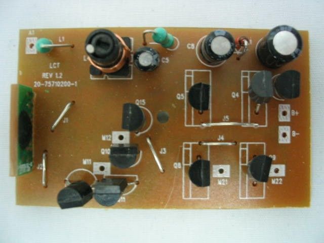
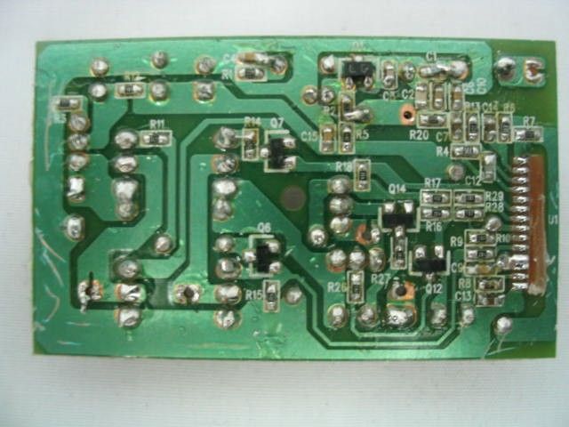
Mattel #B5074 RX 49. 860 MHz Receiver Operational Description The 6.0V car & Truck is full function radio controlled toy car It operates on 6.0 volts supplied by four 1.5 volts alkaline AA batteries or a 6.0V Nicad battery pack It is designed to operate on a single fixed frequency in the 49.82 – 49.90 MHz band. See the attached block diagram and schematic. The vehicle receiver receives and demodulates the AM transmitted signal from the transmitter, using a standard super-regenerative AM receiver/demodulator circuit comprised of ANT1, Q1, L1, L3, L4 and associated passive components. L4 is a tunable core slug inductor that is used to tune the receiver for maximum sensitivity. The output of the AM receiver/demodulator is AC coupled to a high input impedance CMOS inverter is connected to the U1 decoder IC, it is biased into their linear region through C12, C14, C9, R4, R13, R6, R7 and function as amplify, filter and shape the data. After passing through the last inverter stage, the incoming waveform is a digitized enough to be fed into the IN1 pin for on-chip decoding. A Zener regulator circuit comprised of C11, C13, R3, D1, C8, C15, it supplied voltage VDD for the super-regenerative radio, decoder IC. Drive motor is controlled by the U1 decoder IC, low power switching transistors Q6, Q7, and a high power H-bridge comprised of Q4, Q5, Q8, Q9, The Steering Motor is controlled by the U1 decoder IC low power switching transistors Q12,Q14,and a high power H-bridge comprised of Q10,Q11,Q13,Q15, All tuning and verifications are performed by the manufacturer and there are no adjustments which can be made by the user. No external ground is required or used with this receiver.
Test Report
TEST REPORT This document shall not be reproduced either in full or in part except with written approval by the Authorized Representative of CMA Testing. Room 1302, Yan Hing Centre, 9-13 Wong Chuk Yeung St.., Fo Tan, Shatin, Hong Kong. Tel: (852) 2698 8198 Fax: (852) 2695 4177 E-mail: [email protected] Web Site: http://www.cmatcl.com Report No. : AE009886-2 Date : 2004 June 28 Client : Mattel Asia Pacific Sourcing Limited 13/F., South Tower, World Finance Centre, Harbour City, Tsimshatsui, Kowloon, Hong Kong. Sample Description : One(1) submitted sample stated to be 6V Truck of Model No. B5074. Rating : 6 V Rechargeable battery No. of sample(s) : Two(2) sets *** Date Received : 2004 June 16. Test Period : 2004 June 16 ñ 2004 June 24. Test Requested : FCC Part 15 Certification Test Method : FCC Rules and Regulations Part 15 ñ Dec 2003 ANSI C63.4 ñ 2001 Test Result : See attached sheet(s) from page 2 to 11. Conclusion : The submitted sample was found to comply with requirement of FCC Part 15 Subpart B. For and on behalf of CMA Testing and Certification Laboratories Authorized Signature : Page 1 of 11 Danny Chui EMC Engineer - EL. Division FCC ID : PIYB5074-04A4R TEST REPORT This document shall not be reproduced either in full or in part except with written approval by the Authorized Representative of CMA Testing. Room 1302, Yan Hing Centre, 9-13 Wong Chuk Yeung St.., Fo Tan, Shatin, Hong Kong. Tel: (852) 2698 8198 Fax: (852) 2695 4177 E-mail: [email protected] Web Site: http://www.cmatcl.com Report No. : AE009886-2 Date : 2004 June 28 Table of Contents 1 General Information........................................................................................................................ 3 1.1 General Description.................................................................................................................. 3 1.2 Related Submittal Grants.......................................................................................................... 3 1.3 Location of the test site............................................................................................................. 4 1.4 List of measuring equipment..................................................................................................... 5 2 Description of the radiated emission test.......................................................................................... 6 2.1 Test Procedure......................................................................................................................... 6 2.2 Test Result............................................................................................................................... 6 2.3 Radiated Emission Measurement Data....................................................................................... 7 3 Description of the Line-conducted Test............................................................................................ 8 3.1 Test Procedure......................................................................................................................... 8 3.2 Test Result............................................................................................................................... 8 3.3 Graph and Table of Conducted Emission Measurement Data...................................................... 8 4 Photograph..................................................................................................................................... 9 4.1 Photographs of the Test Setup for Radiated Emission and Conduction Emission.......................... 9 4.2 Photographs of the External and Internal Configurations of the EUT........................................... 9 5 Supplementary document............................................................................................................... 10 5.1 Bandwidth............................................................................................................................. 10 6 Appendices............................................................................................................................... 11 Page 2 of 11 FCC ID : PIYB5074-04A4R TEST REPORT This document shall not be reproduced either in full or in part except with written approval by the Authorized Representative of CMA Testing. Room 1302, Yan Hing Centre, 9-13 Wong Chuk Yeung St.., Fo Tan, Shatin, Hong Kong. Tel: (852) 2698 8198 Fax: (852) 2695 4177 E-mail: [email protected] Web Site: http://www.cmatcl.com Report No. : AE009886-2 Date : 2004 June 28 1 General Information 1.1 General Description The equipment under test (EUT) is a superregenerative receiver for 6V Truck operating at 49.860 MHz which is controlled by a LRC circuit. The EUT is powered by 6 V rechargeable battery, and it has a internal receiving antenna. When it received a forward or backward signal, it will going forward or backward. When it received a left or right signal, it will going left or right. The brief circuit description is listed as follows : - Q1 and associated circuit act as superregenerative circuit - Q2 and associated circuit act as voltage readjust - U1 and associated circuit act as decoder - O4~Q9 and associated circuit act as forward & backward motor control - Q10~Q15 and associated circuit act as left & right motor control - R8 and associated circuit act as oscillator for U1 1.2 Related Submittal Grants This is a single application for certification of a receiver. The transmitter for this receiver is authorized by Certification procedure. Page 3 of 11 FCC ID : PIYB5074-04A4R TEST REPORT This document shall not be reproduced either in full or in part except with written approval by the Authorized Representative of CMA Testing. Room 1302, Yan Hing Centre, 9-13 Wong Chuk Yeung St.., Fo Tan, Shatin, Hong Kong. Tel: (852) 2698 8198 Fax: (852) 2695 4177 E-mail: [email protected] Web Site: http://www.cmatcl.com Report No. : AE009886-2 Date : 2004 June 28 1.3 Location of the test…
Text truncated - open the document above for the full version.
Contact Information
Applicant
Joule Mak(Director, Electronic Engineering)
Test Firm
CMA Industrial Development Foundations LimitedStephen Lam
Technical Specifications
| # | Rule Parts | Frequency Range | Power Output |
|---|---|---|---|
| 1 | 15B | 49.86 MHz - 49.86 MHz | - |
Other Applications from Mattel Asia Pacific Sourcing Ltd.
PIY-HTX00-24-A5T
Jan 17, 2024Fisher-Price Link Squad Jam & Count Panda
Equipment Class
DXX - Part 15 Low Power Communication Device TransmitterPIY-HTX03-24-A5T
Jan 17, 2024Fisher-Price Link Squad A to Z Yak
Equipment Class
DXX - Part 15 Low Power Communication Device TransmitterPIY-HTX04-24-A5T
Jan 17, 2024Fisher-Price Link SquadBop & Groove Tiger
Equipment Class
DXX - Part 15 Low Power Communication Device TransmitterPIY-HTW99-24-A5T
Jan 17, 2024Fisher-Price Link Squad Opposites Fox
Equipment Class
DXX - Part 15 Low Power Communication Device TransmitterPIY-HTX01-24-A5T
Jan 17, 2024Fisher-Price Link Squad Crawl n Colors Chameleon
Equipment Class
DXX - Part 15 Low Power Communication Device Transmitter