PIYB6453-03A4RTMH Vertigo
Mattel Asia Pacific Sourcing Ltd.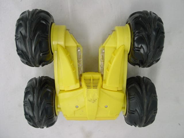
Click to zoom
Application Details
- Equipment Class
- CRR - Superregenerative Receiver
- Date of Grant
- Apr 22, 2003
- Application Purpose
- Original Equipment
- Date of Application
- Apr 22, 2003
- Equipment Note
- TMH Vertigo
- Frequency Range
- 49.86000000 - 49.86000000
- Country
- Hong Kong
Documents & Files
Document Text
Text extracted from the exhibit documents filed with the FCC. Open a document above to read the original.
Block Diagram
F/B MOTOR L/R MOTOR S1 BLOCK-DIAGRAMB6453 RECEIVER 49.860MHzPCB : RXB6453 RX&B6453 RX MAIN PCB SUPER CIRCUIT REGULATOR VOLTAGE RIPPLE FILTER VI2 VO1 VI1 VDD TURBO FORWARD BACKWARD LDB VO2 GND S1 OSC1 OSC0 RIGHT LEFT ROB CONTROL LOGIC DRIVE CIRCUIT NiMH BATTERY PACK 7.2V + _ MOTOR DRIVE CIRCUIT AMP RX2 COUNTER PLA LATCH OSCILLATORLIMINGGENERATORDECODINGCIRCUIT M M MOTOR POWER ON OFF REGENERATIVE C0 3 C1 4 C2 5 C3 6 RESET 2 VDD 8 VSS 1,7 XI 9 AUD 10 D0 17 D1 16 D2 15 D3 14 D4 13 D5 12 U3 SPC21A1 LED DRIVER CIRCUIT 1110 13 D 98 14 C 54 2 A 76 1 B OVER CURRENT AND LOW VOLTAGE PROTECTIVE CIRCUIT BBRRGG
Operational Description
B6453 TMH VERTIGO 49.860MHz RECEIVER OPERATIONAL DESCRIPTION The TMH Vertigo is a full function radio controlled toy truck. It operates on 7.2Volts supplied by 7.2V NiMH battery pack. It is designed to operate on a single fixed frequency in the 49.82-49.90MHz band .See the attached block diagram and schematic. The modulated RF signal from the transmitter induces an electrical signal into the truck’s permanently attached internal wire antenna. The vehicle receiver receives and demodulates the AM transmitted signal from the transmitter, using a standard super-regenerative AM receiver/demodulator circuit comprised of ANT1, Q4, L1, L2, L3 and associated passive components. L2 is a tunable core slug inductor that is used to tune the receiver for maximum sensitivity. The output of the AM receiver/demodulator is AC coupled to a high input impedance CMOS inverter stage of the U1 decoder IC biased into their linear region through C19, C20, C23, R22, R23, R25, R27 which amplify, filter and shape the data. After the last inverter stage the incoming waveform is a digitized enough to be fed into the SI pin for on-chip decoding. A Zener regulator circuit comprised of C25, C21, D10A, Q3, R17, and R18 creates the supply voltage, VDD for the super-regenerative radio, decoder IC and Comparator section. Drive motors M1 and M2 are controlled by the U1 decoder IC, low power switching transistors Q7, Q8, and Q13, Q14 and a high power H-bridge comprised of Q5, Q6, Q9, Q10 and Q11, Q12, Q15, Q16 respectively. R32 and R37 are current sense resistors that permit a proportional sense voltage to be developed above them that is proportional to the amount of current through the bridge. The M1 Sense and M2 Sense signals are fed into low pass filters composed of R8 & C6 and R3 & C3 which filter transisent current spikes and then into U2A and U2B, 2 sections of an LM339 quad comparator. These two signals are independently compared to identical reference voltages established by R1 & R2 and R5 & R6 that establish the trip point for the output of U2A and U2B, the over current output. By using negative logic the outputs can be OR’ed together to generate and common over current condition output. When the output is active, over current is true, C8 will begin discharging through R47. After a delay the voltage on pin 8 of U2C is less than the reference voltage established by R7 & R46 causing the Shutdown output on pins 14 to switch to VDD. This inturn sinks the over current input to U2C to ground and latches the motors off via Q2, D5, D6, D7, D8. The wheels of the vehicle are “freewheeling” at this point and can only be reactivated when the control output (joystick control) signal is released and reengaged. D1, D2, D3, D4, and Q25, Q24 act to monitor joystick states as control signals at the output of the U1 decoder IC. U2D acts as a low battery voltage dector. When the battery voltage drops to the setting value, R60 and R59 will detect this change, the voltage on pin11 will be less than the reference voltage (on pin10) established by R12 and D19, causing the shutdown output on pin14. It also causes no output to motor M1 and M2, until the control output (joystick control) signal is released and reengaged. When the joystick is released the output of Q24 toggles state, resets the latch and the vehicle is returned to its normal play state. Receiving some kind of control signal from transmitter, Pin11 and Pin6, or Pin10 and Pin 7 from U1 will have signal and will trigger integrated circuit (U3), LEDS will flash. All tuning and verifications are performed by the manufacturer and there are no adjustments which can be made by the user. No external ground is required or used with this receiver.
Schematics
1 2 3 4 56 AB C D 6 5 4 3 2 1 D C BA Title Number Revision Size B Date: 8-Apr-2003 Sheet of File: D:\lmh\..\FCCB6453RX-49C.sch Drawn By: ANT1 L1 2.2uH C123pF C13 6pF L2 7.5T C14 25pF C24 Mylar 0.0022uF L3 3.3uH Q4 C380 Y R24820 R21 270K R202.2K R19 4.3K C18 4.7uF C17 0.01uF C26 0.1uF C21 0.1uF C25 220uF R22 2.2M R23 2.2K C19 120pF C20 0.1uF R25 2.2 M R272.2K C23 1000pF 1 1 2 2 3 3 4 4 5 5 6 6 7 7 8 8 9 9 10 10 11 11 12 12 13 13 14 14 15 15 16 16 U1RX2C/PT8A978BP R26 140K/113K/130K R30 820 R31 820 R17 330 D10A 3.3V Q3 2SA1015Y R18 4.3K R45 47/1W Q6 2SA1357Y/2SB1658 Q5 2SA1357Y/2SB1658 Q8 S8050D Q9 2SC3420GR/2SD2583 Q7 S8050D Q102SC3420GR/2SD2583 R2847/1W R3 1K R32 0.02/1W M1 VDD1 D1 1N4148 D2 1N4148 D3 1N4148 D4 1N4148 R36 820 R35 820 D5 1N4148 D6 1N4148 D7 1N4148 D8 1N4148 R60 33K R59 4.75k 11 10 13 U2D LM339 R15 3.3K Q2 KSC1623GR R11 5.1K R10 4.7K 98 14 U2CLM339 Q1 KSC1623GR C3 3.3uF 54 2 U2A LM339 C2 0.1uF R133K R2 680 R38 10K VDD1 VDD1 VDD1 R710K R46 7.5K C50.1uF R47 1.5M D9 1N4148 C8 22uF VDD1 SW1 10A 7.2V Pack R34 47/1W Q12 2SA1357Y/2SB1658 Q11 2SA1357Y/2SB1658 Q14 S8050D Q15 2SC3420GR/2SD2583 Q16 2SC3420GR/2SD2583 R33 47/1W R81K R37 0.02/1W M2 Q13 S8050D VCC C6 3.3uF 76 1 U2BLM339 C4 0.1uF R5 33K R6 680 VDD1 R50180 LED3 Blue LED8 Green Q23 KSC1623GR 10V TMH Vertigo(49MHz USA) B6453 01 R9 1K R13 1K C29 0.1 uF C30 0.1 uF C33 0.1 uF C34 0.1 uF D11 1N4001 D12 1N4001 D13 1N4001 D14 1N4001 D15 1N4001 D16 1N4001 D18 1N4001 D17 1N4001 +/-1% VCC +/-1% +/-1% +/-1%+/-1% R161K R39 1K R52 180 LED5 Blue LED10 Green R51 200 LED9 Red Q22 KSC1623GR VCC LED7 Red R48 130 LED6 Blue Q19 KSC1623GR R43 130 LED4 Blue Q18 KSC1623GR C41 0.1uF R53 100K C0 3 C1 4 C2 5 C3 6 RESET 2 VDD 8 VSS 1,7 XI 9 AUD 10 D0 17 D1 16 D2 15 D3 14 D4 13 D5 12 U3 SPC21A1 VDD1 L4 10uH C42 0.1uF R58 97.6K R54 2.2K R55 2.2K R56 2.2K R57 2.2K L' Q2C R' B' F' F R B L IN2 IN3 OUT4 OUT1 IN2 IN3 OUT4 C27 0.1 uF C31 0.1 uF Switch is below the CAR C35 0.1uF VDD1 L5 10uH R49 200 OUT1 R44 130 R42 130 Red LED7 Blue LED3 Green LED8 Blue LED6 Blue LED5 Green LED10 Blue LED4 Red LED9 1 2 3 4 D0' D1' D4' D2' Q25 2SC1623GR Q24 2SC1623GR R14 10K R12 1K R4110K VCC D191N4148 C43 0.1uF 3 12 C7 3.3uF
Test Report
TEST REPORT This document shall not be reproduced either in full or in part except with written approval by the Authorized Representative of CMA Testing. Room 1401-3, Yan Hing Centre, 9-13 Wong Chuk Yeung St.., Fo Tan, Shatin, Hong Kong. Tel: (852) 2698 8198 Fax: (852) 2695 4177 E-mail: [email protected] Web Site: http://www.cmatcl.com Report No. : AD003269-1 Date : 2003 April 16 Client : Mattel Asia Pacific Sourcing Limited 13/F., South Tower, World Finance Center, Harbour City, Tsimshatsui, Kowloon, Hong Kong. Sample Description : One(1) submitted sample stated to be Mattel item : TMH Vertigo of Model No. B6453 . Rating : 1 x 7.2 V, NiCd type rechargeable battery No. of sample(s) : Two(2) pieces *** Date Received : 2003 March 03. 2003 April 03. Test Period : 2003 March 03 – 2003 March 06. 2003 April 03 – 2003 April 04. Test Requested : FCC Part 15 Certification Test Method : FCC Rules and Regulations Part 15 – May 2002 ANSI C63.4 – 1992 Test Result : See attached sheet(s) from page 2 to 11. Conclusion : The submitted sample was found to comply with requirement of FCC Part 15 Subpart B. For and on behalf of CMA Testing and Certification Laboratories Authorized Signature : Page 1 of 11 Danny Chui EMC Engineer - EL. Division FCC ID : PIYB6453-03A4R TEST REPORT This document shall not be reproduced either in full or in part except with written approval by the Authorized Representative of CMA Testing. Room 1401-3, Yan Hing Centre, 9-13 Wong Chuk Yeung St.., Fo Tan, Shatin, Hong Kong. Tel: (852) 2698 8198 Fax: (852) 2695 4177 E-mail: [email protected] Web Site: http://www.cmatcl.com Report No. : AD003269-1 Date : 2003 April 16 Table of Contents 1 General Information........................................................................................................................ 3 1.1 General Description.................................................................................................................. 3 1.2 Related Submittal Grants.......................................................................................................... 3 1.3 Location of the test site............................................................................................................. 4 1.4 List of measuring equipment..................................................................................................... 5 2 Description of the radiated emission test.......................................................................................... 6 2.1 Test Procedure......................................................................................................................... 6 2.2 Test Result............................................................................................................................... 6 2.3 Radiated Emission Measurement Data....................................................................................... 7 2.3 Radiated Emission Measurement Data....................................................................................... 8 3 Description of the Line-conducted Test............................................................................................ 9 3.1 Test Procedure......................................................................................................................... 9 3.2 Test Result............................................................................................................................... 9 3.3 Graph and Table of Conducted Emission Measurement Data...................................................... 9 4 Photograph................................................................................................................................... 10 4.1 Photographs of the Test Setup for Radiated Emission and Conduction Emission........................ 10 4.2 Photographs of the External and Internal Configurations of the EUT......................................... 10 5 Supplementary document............................................................................................................... 10 5.1 Bandwidth............................................................................................................................. 10 6 Appendices.................................................................................................................................... 11 Page 2 of 11 FCC ID : PIYB6453-03A4R TEST REPORT This document shall not be reproduced either in full or in part except with written approval by the Authorized Representative of CMA Testing. Room 1401-3, Yan Hing Centre, 9-13 Wong Chuk Yeung St.., Fo Tan, Shatin, Hong Kong. Tel: (852) 2698 8198 Fax: (852) 2695 4177 E-mail: [email protected] Web Site: http://www.cmatcl.com Report No. : AD003269-1 Date : 2003 April 16 1 General Information 1.1 General Description The equipment under test (EUT) is a superregenerative receiver for TMH Vertigo operating at 49.860 MHz which is controlled by a crystal. The EUT is powered by 7.2 V NiMH battery pack. The EUT receive the signal from transmitter for move forward, backward, left and right direction. The brief circuit description is saved with filename : OpDes.pdf 1.2 Related Submittal Grants This is a single application for certification of a receiver. The transmitter for this receiver is authorized by Certification procedure. Page 3 of 11 FCC ID : PIYB6453-03A4R TEST REPORT This document shall not be reproduced either in full or in part except with written approval by the Authorized Representative of CMA Testing. Room 1401-3, Yan Hing Centre, 9-13 Wong Chuk Yeung St.., Fo Tan, Shatin, Hong Kong. Tel: (852) 2698 8198 Fax: (852) 2695 4177 E-mail: [email protected] Web Site: http://www.cmatcl.com Report No. : AD003269-1 Date : 2003 April 16 1.3 Location of the test site Radiated emissions measurements are investigated and taken pursuant to the procedures of ANSI C63.4 – 1992. An Open Area Testing Site is set up for investigation and located at : Top of the Roof, Ya…
Text truncated - open the document above for the full version.
Contact Information
Applicant
Joule Mak(Director, Electronic Engineering)
Test Firm
CMA Industrial Development Foundations LimitedStephen Lam
Technical Specifications
| # | Rule Parts | Frequency Range | Power Output |
|---|---|---|---|
| 1 | 15B | 49.86 MHz - 49.86 MHz | - |
Other Applications from Mattel Asia Pacific Sourcing Ltd.
PIY-HTX00-24-A5T
Jan 17, 2024Fisher-Price Link Squad Jam & Count Panda
Equipment Class
DXX - Part 15 Low Power Communication Device TransmitterPIY-HTX03-24-A5T
Jan 17, 2024Fisher-Price Link Squad A to Z Yak
Equipment Class
DXX - Part 15 Low Power Communication Device TransmitterPIY-HTX04-24-A5T
Jan 17, 2024Fisher-Price Link SquadBop & Groove Tiger
Equipment Class
DXX - Part 15 Low Power Communication Device TransmitterPIY-HTW99-24-A5T
Jan 17, 2024Fisher-Price Link Squad Opposites Fox
Equipment Class
DXX - Part 15 Low Power Communication Device TransmitterPIY-HTX01-24-A5T
Jan 17, 2024Fisher-Price Link Squad Crawl n Colors Chameleon
Equipment Class
DXX - Part 15 Low Power Communication Device Transmitter