PIYH6918-05A4RREBOUND SUPER BIKE
Mattel Asia Pacific Sourcing Ltd.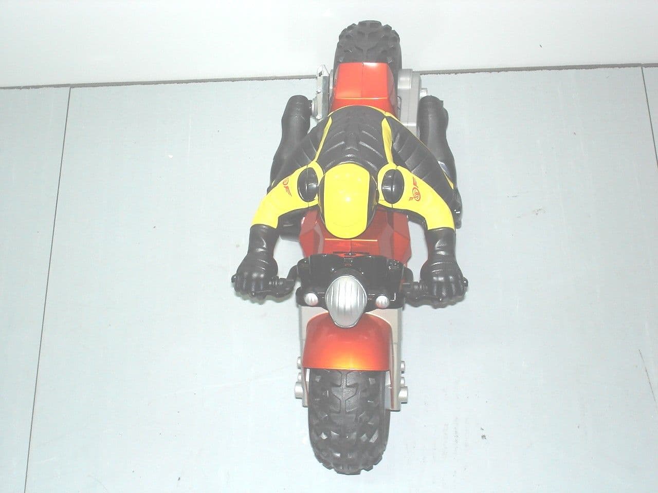
Click to zoom
Application Details
- Equipment Class
- CRR - Superregenerative Receiver
- Date of Grant
- Jun 28, 2005
- Application Purpose
- Original Equipment
- Date of Application
- Jun 28, 2005
- Equipment Note
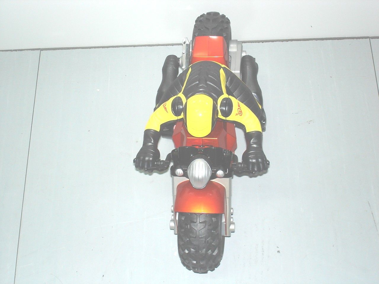
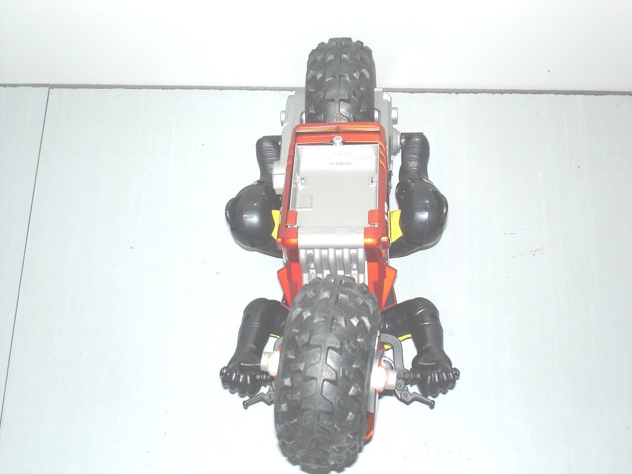
- REBOUND SUPER BIKE
- Frequency Range
- 49.86000000 - 49.86000000
- Country
- Hong Kong
Documents & Files
Document Text
Text extracted from the exhibit documents filed with the FCC. Open a document above to read the original.
ID Label/Location Info
PDF 文件使用 "pdfFactory Pro" 试用版本创建 www.fineprint.com.cn
Operational Description
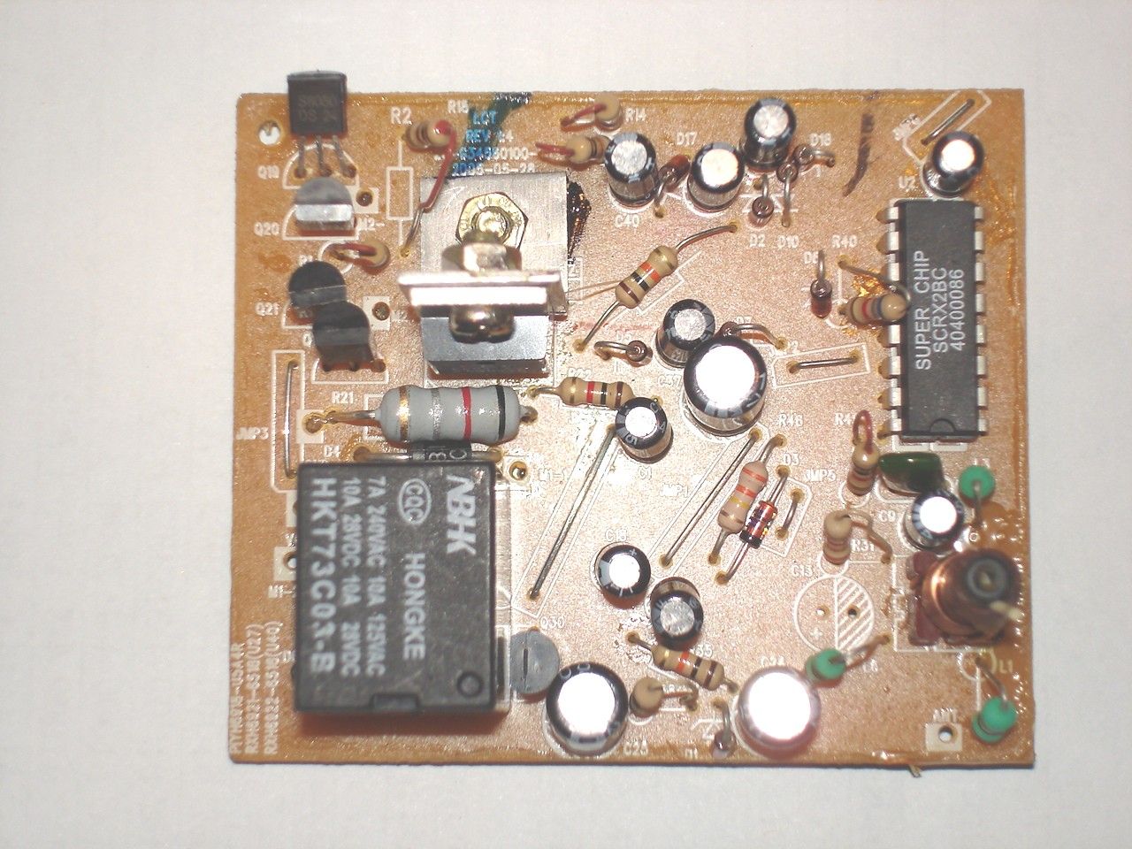
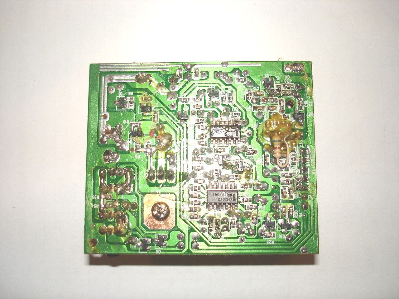
REBOUND SUPER BIKE 49. 860 MHz Receiver Operational Description The REBOUND SUPER BIKE is a full function radio controlled toy car. It operates on 7.2 volts rechargeable NiMH pack battery . and is designed to operate on a single fixed frequency in the 49.82 ñ 49.90 MHz band. See the attached block diagram and schematic. The modulated RF signal from the transmitter induces an electrical signal into the carís permanently attached metal internal antenna. The electrical signal is selectively amplified by a super regenerative input circuit (Q9,Q27,L2,L3,L1,C10,C7,C8). The signal is then input into an integrated circuit (U2), where the signal is amplified and decoded two pairs of digital outputs Q3,Q4,Q8 control the percentage of power to the driving motor M1.Steering motor driving circuit comprised of Q5,Q6,Q18,Q19,Q20,Q21. The forward signal is then input into a delay change state circuit(U1-C,Q13) , after a preset time Q13 will change the U2 MOD pin to low voltage , then the forward & backward will output the lower percentage of power . The lower percentage signal is then input into a change PWM circuit , which the signal is adjusted and send to the control driving motor circuit . The backward signal pass Q10,Q13 then change the U2 MOD pin to high voltage , then the forward & backward will output the full power . The battery voltage is detected by a low voltage protect circuit (U1-B,Q7,Q11) . When the low voltage protection sustain a preset time , Q7 will cut off U2ís signal input. Next play need switch off/on SW. The operating current of motor M1 is detected by a high current protect circuit (U3-A,U3-B,U3-C,Q2,Q12). When the over current sustain preset time , Q2 will cut off the forward signal , next operate trigger can resume to normal. All tuning and verifications are performed by the manufacturer and there are no adjustments that can be made by the user. No external ground is required or used with this receiver. REBOUND SUPER BIKE 49.860MHZ mattel part H6918 receiver FCC ID: PIYH6918-05A4R
Schematics
PDF 文件使用 "pdfFactory Pro" 试用版本创建 www.fineprint.com.cn
Test Report
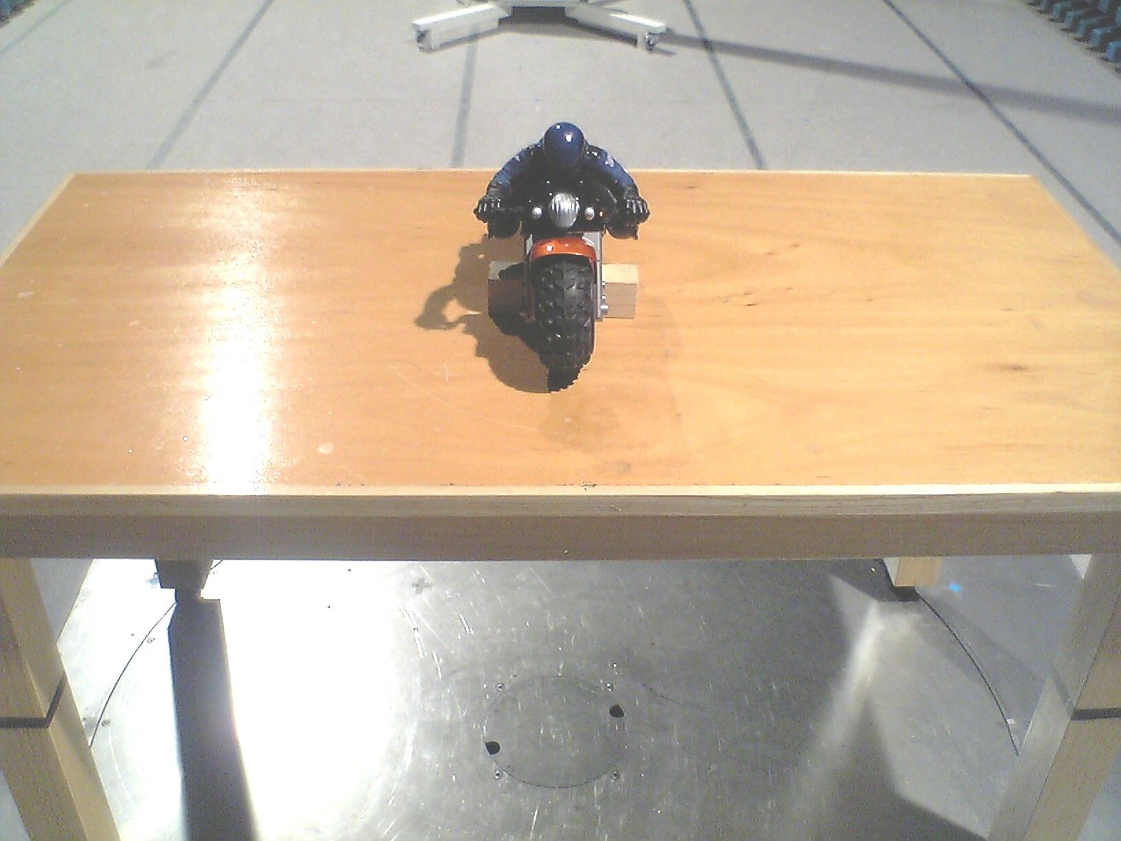
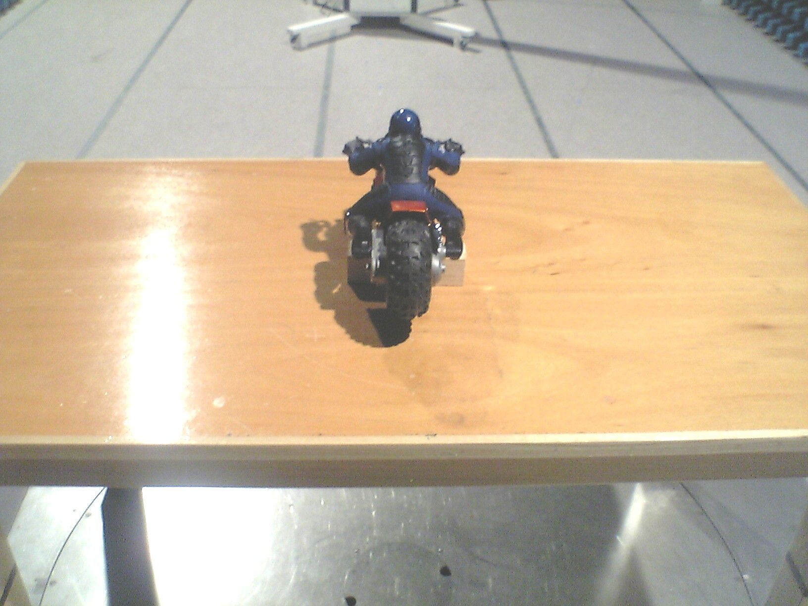
TEST REPORT Report No. : AF013714-001 Date : 2005 June 27 For and on behalf of CMA Testing and Certification Laboratories Authorized Signature : Page 1 of 11 Danny Chui EMC Engineer - EL. Division FCC ID : PIYH6918-05A4R This document shall not be reproduced either in full or in part except with written approval by the Authorized Representative of CMA Testing. Room 1302, Yan Hing Centre, 9-13 Wong Chuk Yeung St.., Fo Tan, Shatin, Hong Kong. Tel: (852) 2698 8198 Fax: (852) 2695 4177 E-mail: [email protected] Web Site: http://www.cmatcl.com Application No. : LF209282(1) Client : Mattel Asia Pacific Sourcing Limited 13/F., South Tower, World Finance Centre, Harbour City, Tsimshatsui, Kowloon, Hong Kong. Sample Description : One(1) submitted sample stated to be Rebound Super Bike of Model No. G3456 Rating : 1 x 7.2V rechargeable battery No. of submitted sample : One (1) piece*** Date Received : Test Period : Test Requested : Test Method : Test Result : Conclusion : 2005 June 08 2005 June 08 – 2005 June 20 FCC Part 15 Certification FCC Rules and Regulations Part 15 – July 2004 ANSI C63.4 – 2003 See attached sheet(s) from page 2 to 11. The submitted sample was found to comply with requirement of FCC Part 15 Subpart B. TEST REPORT Report No. : AF013714-001 Date : 2005 June 27 Page 2 of 11 FCC ID : PIYH6918-05A4R This document shall not be reproduced either in full or in part except with written approval by the Authorized Representative of CMA Testing. Room 1302, Yan Hing Centre, 9-13 Wong Chuk Yeung St.., Fo Tan, Shatin, Hong Kong. Tel: (852) 2698 8198 Fax: (852) 2695 4177 E-mail: [email protected] Web Site: http://www.cmatcl.com Table of Contents 1 General Information .................................................................................................................................. 3 1.1 General Description ........................................................................................................................... 3 1.2 Location of the test site ...................................................................................................................... 4 1.3 List of measuring equipment.............................................................................................................. 5 2 Description of the radiated emission test .................................................................................................. 6 2.1 Test Procedure ................................................................................................................................... 6 2.2 Test Result ......................................................................................................................................... 6 2.3 Radiated Emission Measurement Data .............................................................................................. 7 3 Description of the Line-conducted Test .................................................................................................... 8 3.1 Test Procedure ................................................................................................................................... 8 3.2 Test Result ......................................................................................................................................... 8 3.3 Graph and Table of Conducted Emission Measurement Data ........................................................... 8 4 Photograph ................................................................................................................................................ 9 4.1 Photographs of the Test Setup for Radiated Emission and Conduction Emission............................. 9 4.2 Photographs of the External and Internal Configurations of the EUT............................................... 9 5 Supplementary document ......................................................................................................................... 10 5.1 Bandwidth ........................................................................................................................................ 10 5.2 Duty Cycle ....................................................................................................................................... 10 6 Appendices................................................................................................................................................ 11 TEST REPORT Report No. : AF013714-001 Date : 2005 June 27 Page 3 of 11 FCC ID : PIYH6918-05A4R This document shall not be reproduced either in full or in part except with written approval by the Authorized Representative of CMA Testing. Room 1302, Yan Hing Centre, 9-13 Wong Chuk Yeung St.., Fo Tan, Shatin, Hong Kong. Tel: (852) 2698 8198 Fax: (852) 2695 4177 E-mail: [email protected] Web Site: http://www.cmatcl.com 1 General Information 1.1 General Description The equipment under test (EUT) is a superregenerative receiver for Rebound Super Bike. Operating at 49.860MHz which is controlled by a LRC circuit. The EUT is powered by 1 x 7.2V rechargeable battery. When it switch on, it can receive a radio signal and running to difference direction. The brief circuit description is listed as follows : - Q9, Q27 and associated circuit act as super regenerative circuit. - U1, U2, Q10, Q13 and associated circuit act as decoder. - Q1, Q3, Q4, Q8, Q2, U3 and associated circuit act as motor control for M1. - Q18, Q19, Q20, Q21 and associated circuit act as motor control for M2. - Q7, Q11 and associated circuit act as voltage control. TEST REPORT Report No. : AF013714-001 Date : 2005 June 27 Page 4 of 11 FCC ID : PIYH6918-05A4R This document shall not be reproduced either in full or in part except with written approval by the Authorized Representative of CMA Testing. Room 1302, Yan Hing Centre, 9-13 Wong Chuk Yeung St.., Fo Tan, Shatin, Hong Kong. Tel: (852) 2698 8198 Fax: (852) 2695 4177 E-mail: [email protected] Web Site: http://www.cmatcl.com 1.2 Locat…
Text truncated - open the document above for the full version.
Contact Information
Applicant
Joule Mak(Director, Electronic Engineering)
Test Firm
Bureau Veritas Consumer Products Services (H.K.)Kent Lai
Technical Specifications
| # | Rule Parts | Frequency Range | Power Output |
|---|---|---|---|
| 1 | 15B | 49.86 MHz - 49.86 MHz | - |
Other Applications from Mattel Asia Pacific Sourcing Ltd.
PIY-HTX00-24-A5T
Jan 17, 2024Fisher-Price Link Squad Jam & Count Panda
Equipment Class
DXX - Part 15 Low Power Communication Device TransmitterPIY-HTX03-24-A5T
Jan 17, 2024Fisher-Price Link Squad A to Z Yak
Equipment Class
DXX - Part 15 Low Power Communication Device TransmitterPIY-HTX04-24-A5T
Jan 17, 2024Fisher-Price Link SquadBop & Groove Tiger
Equipment Class
DXX - Part 15 Low Power Communication Device TransmitterPIY-HTW99-24-A5T
Jan 17, 2024Fisher-Price Link Squad Opposites Fox
Equipment Class
DXX - Part 15 Low Power Communication Device TransmitterPIY-HTX01-24-A5T
Jan 17, 2024Fisher-Price Link Squad Crawl n Colors Chameleon
Equipment Class
DXX - Part 15 Low Power Communication Device Transmitter