PIYH6928-05A4TSHELL SHOCKER
Mattel Asia Pacific Sourcing Ltd.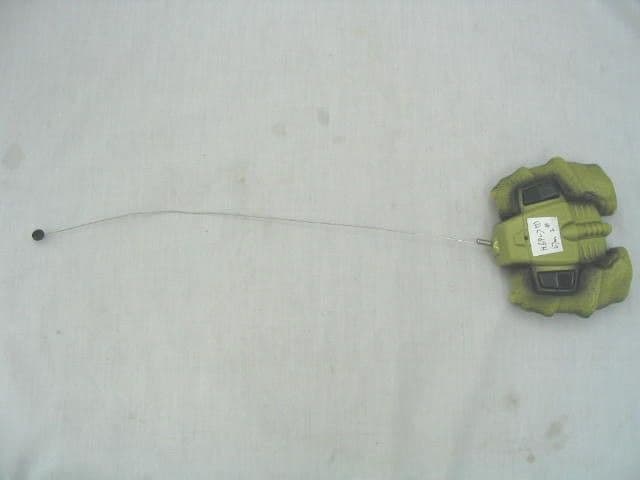
Click to zoom
Application Details
- Equipment Class
- DXX - Part 15 Low Power Communication Device Transmitter
- Date of Grant
- Jun 23, 2005
- Application Purpose
- Original Equipment
- Date of Application
- Jun 23, 2005
- Equipment Note
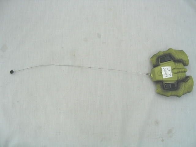
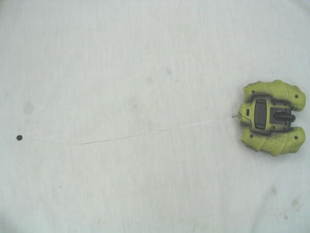
- SHELL SHOCKER
- Frequency Range
- 49.86000000 - 49.86000000
- Country
- Hong Kong
Documents & Files
Document Text
Text extracted from the exhibit documents filed with the FCC. Open a document above to read the original.
Users Manual
< I O q q w t r e w TYCO R/C SUPPORT Questions or problems with your product? DON’T RETURN IT TO THE STORE! Just call us for help. U.S. consumers may also register their products at this number. 1 888 557-TYCO (8926) ® tycorc.com Keep these instructions for future reference: they contain important information.IMPORTANT: Please read all “Consumer Information” before operating your vehicle. G3457-0920 G3457-9993-S1 X CAUTION: Surfaces may become hot and cause burns if electronics get wet. Do not operate vehicle through water or snow. I.CREATURE FEATURES Vehicle Transmitter Vehicle q ON/OFF switch w Battery compartment cover Transmitter q Left button controls left shells w Right button controls right shells e Bottom left toggle closes Shell Shocker™ r Bottom right toggle opens Shell Shocker™ t ON/OFF switch II.HOW TO CONTROL THE BEAST! Basic driving q FORWARD w LEFT e RIGHT r SPIN LEFT t SPIN RIGHT y Closes Shell Shocker™ u Opens Shell Shocker™ Shocking transformations! Shell Shocker ™ features my ingenious armor shell configuration that spins and opens for all kinds of shocking stunts! Here are a few of my favorites. A Whirlwind spin shield! With Shell Shocker ™ in explore mode (all shell armor open outward) push the left button up and the right button down. For high-speed spins in the opposite direction, push the left button down and the right button up! A NOT RECOMMENDED FOR CHILDREN UNDER 8 YEARS OF AGE. AS WITH ALL ELECTRIC PRODUCTS,PRECAUTIONS SHOULD BE OBSERVED DURING HANDLING AND USE TO PREVENT ELECTRIC SHOCK. INPUT: 120VAC, 60Hz, 0.1A. OUTPUT:8.5VDC, 440mA, 3.74VA. CAUTION-ELECTRIC TOY: q w er y t u B Snap attack tail! With Shell Shocker ™ in explore mode (all shell armor open outward) push both buttons up to drive forward. When you hit full speed, quickly jam both buttons down. Your vehicle will snap attack with its tail! * Note: In this mode the tail will come down fast! Keep feet, fingers and anything that breathes away from Shell Shocker™ C Defender bender! With Shell Shocker ™ in explore mode (all armor open outward) push the left button up and the right button down. As the Shell Shocker™ spins press the bottom left toggle switch beneath the transmitter. The shells will begin closing even as the Shell Shocker™ spins frantically about! Now open it up mid spin by pressing the right toggle switch beneath the transmitter. III. HOW TO BRING MY SHELL SHOCKER ™ TO LIFE! Requires a 7.2v Tyco ® Pro FlexPak ® (NiMH) battery pack for vehicle and a 9v battery for transmitter . Vehicle 1. First turn Shell Shocker upside down, tail facing you. 2. Now unscrew the battery compartment cover (screwdriver not included). 3. Hold the Tyco ® Pro FlexPak ® battery pack(not included) facing up as shown. 4. Now slide the battery end marked #1 down into the battery compartment. Before you press down on the batterypack make sure to place the ribbon under- neath the battery for easy pull out later. 5. To remove the battery, unscrew the battery door, pull on the ribbon and lift out the battery. Transmitter 1. Open the battery door as shown. 2. Install one 9v battery (not included) with polarity (+/-) as shown inside the battery compartment. 3. Close the battery door. 1 2 B C 7.2v d.c. NiMH, 6 x Sub C, 1600 mAh (not included) ; IV. DR. KRAIZD’S TOP SECRET QUICK TIPS qWhen ShellShocker™ starts to lose power you’ll start to lose performance. It's time for a recharge. As a rule, you should always start with a fully charged battery. wBe forewarned-- Shell Shocker’s running time may change depending on your driving style. eRadio interference can mess up the signals you’re sending, causing Shell Shocker™ to perform errati- cally. Things to look for that may be causing the interference: other R/C vehicles running on the same frequency, electrical wires, large buildings, CB radios, secret government agents attempting to thwart my brilliant creations or other wireless gear that can cause interference. rPoint your transmitter antenna up - not down toward Shell Shocker™. If Shell Shocker™ escapes your antenna’s grasp, you can kiss proper functioning goodbye and send your poor deranged creature into its default blink mode. tDon’t drive Shell Shocker™ through water or snow. Not only won’t you get very far, you might ruin the creature. If my precious Shell Shocker™ does get wet, wipe it with a towel and allow it to dry completely. yDon’t store Shell Shocker™ near heat or in direct sunlight. Always turn the switches OFF and, if you’re not planning on taking the little creature out of its cave for a while, remove all the batter- ies...really. It’s amazing how one leaky battery can bring all my brilliant work to ruin! * Please recharge your battery when you find the Shell Shocker™'s eyes blink slowly. If the Shell Shocker™ is blocked by some obstacle, its eyes will blink in a medium speed. If it cannot receive any signal from the TX, the eyes will blink fast. ìV.HANDLING THE BEAST WITH CARE! Note to Adults: To ensure that the child’s play is both safe and fun, please review all the operating instructions and safety tips with your child. Safety Tips • Yes, Shell Shocker™ is a multi-terrain vehicle but you should NEVER, EVER drive it on the street! • DO NOT pick up Shell Shocker™ while in motion. Take your fingers off the Transmitter buttons and then pick it up. X CAUTION:Keep fingers, hair and loose clothing away from ShellShocker™ while it’s on. • In ‘Snap Attack’ mode the tail comes down fast. Keep feet, fingers and anything that moves away from Shell Shocker™ when practicing this mode. • Adult supervision is recommended when Shell Shocker™ is being used. • To avoid accidental or unwanted operation, remove all the batteries when not in use. Always turn Shell Shocker™ OFF before removing the batteries. q w e r t y BATTERY SAFETY INFORMATION In exceptional circumstances batteries may leak fluids that can cause a chemical burn injury or ruin your product. To avoid battery leakage: • Non-rechargeable batteries are not to be r…
Text truncated - open the document above for the full version.
Block Diagram
ANTENNA CRYSTALOSCILLATOR MODULATORRF AMPLIFIER VOLTAGEREGULATOR BLOCK-DIAGRAMH6928 TRANSMITTERMAIN PCB :PIYH6928-05A4T FILTER 49.86MHZ 9V BATTERY POWER ON/OFF 3mm LED EM78156EH OSC1 VDDVSS U1 Left Forward Left BackwardRight ForwardRight BackwardPetal OpenPetal Close
ID Label/Location Info
17.0mm 27.0mm
Operational Description
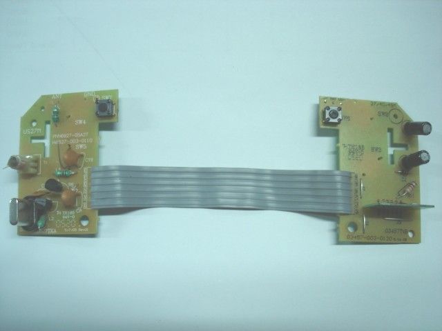
SHELL SHOCKER H6928 49.86 MHz TRANSMITTER OPERATIONAL DESCRIPTION The Shell Shocker control transmitter is a low powered, hand held unit for controlling the movement of a toy ball . The transmitter is powered by a 9-volt battery. It is designed to operate on a single fixed frequency in the 49.82~49.90 MHz band. See the attached block diagram and schematic. Input switches trigger an integrated circuit ( U1 ) which produces the digital control signals that will modulate the carrier signal. The carrier signal is generated by a crystal oscillator circuit comprised of a 49.86MHz crystal ( Y1 ) and a pnp transistor ( Q2 ). The RF carrier signal is modulated by the digital control signal at the base of an RF amplifier stage ( Q3 ). The modulated output of the RF amplifier stage is capacitively coupled ( via C12 ) to the antenna through a “ pi“ matching network comprised of C13, T1 and C14. The antenna is about 15 inches length and permanently attached. A LED acts as a power-on indicator . All tuning and verifications are performed by the manufacturer and there are no adjustments that can be made by the user. No external ground is required or used with this transmitter. SHELL SHOCKER 49.86 MHz Mattel Part H6928 Transmitter FCC ID: PIYH6928-05A4T
Schematics
1 2 3 4 56 ABC D 6 5 4 3 2 1 D CBA Title Number Revision Size A4 Date: 9-Jun-2005 Sheet of File: D:\lmh\..\H6928(US49M)-00.sch Drawn By: R15 1K R14 1K R13 1K R12 1K R11 1K SW6 Petal Open SW5 Right Backward SW4 Right Forward SW3 Left Backward SW2 Left Forward 4.3V C3 47 uF C4 0.1uF Y1 49.86MHZ Q2 2SA1015GR R6 150 R5 300K C58PF C6 8PF C747PF C9 47PF R7 68k Q3 2SC1815GR R8 100 C1247PF C13 33PF C110.01uF C14 33PF C17 22pF ANT C8 0.01uF T1 7B-ZT3330-4 C10 18PF L2 1.2uH R10 3.3K +/-1% L3 0.56uH C15 0.1uF R16 1K SW7 Petal Close R9 51K C16 0.1UF P5.1 VDD RST VSS OSCI TCC H6928 (US49M) 00 Shell Shocker P60P61P62P63P66P67 L53.3uH EM78156EH lmh U1 1 C19 0.01uF D2 R4330 9V BATTERY SW1 ON OFF R1 680 D1 3 mm Red LED R17 1 OHM C2 0.1uF C1 47 uF
Test Report
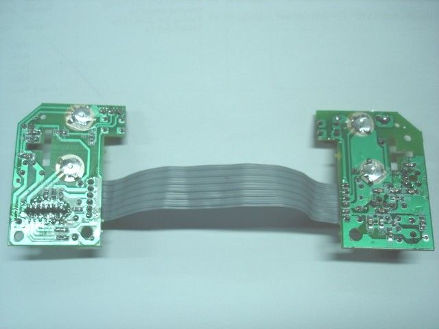
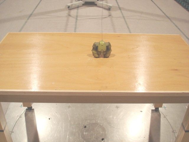
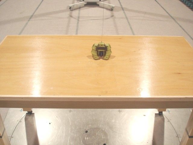
TEST REPORT Report No. : AF013232-001 Date : 2005 June 24 For and on behalf of CMA Testing and Certification Laboratories Authorized Signature : Page 1 of 11 Danny Chui EMC Engineer - EL. Division FCC ID : PIYH6928-05A4T This document shall not be reproduced either in full or in part except with written approval by the Authorized Representative of CMA Testing. Room 1302, Yan Hing Centre, 9-13 Wong Chuk Yeung St.., Fo Tan, Shatin, Hong Kong. Tel: (852) 2698 8198 Fax: (852) 2695 4177 E-mail: [email protected] Web Site: http://www.cmatcl.com Application No. : LF210675(0) Client : Mattel Asia Pacific Sourcing Ltd. 13/F., South Tower, World Finance Centre, Harbour City, Tsim Sha Tsui, Kowloon, Hong Kong. Sample Description : One(1) submitted sample stated to be Shell Shocker of Model No. H6928 Rating : 1 x 9V size battery No. of submitted sample : One (1) piece *** Date Received : Test Period : Test Requested : Test Method : Test Result : Conclusion : 2005 June 08 2005 June 08 – 2005 June 20 FCC Part 15 Certification FCC Rules and Regulations Part 15 – July 2004 ANSI C63.4 – 2003 See attached sheet(s) from page 2 to 11. The submitted sample was found to comply with requirement of FCC Part 15 Subpart C. TEST REPORT Report No. : AF013232-001 Date : 2005 June 24 Page 2 of 11 FCC ID : PIYH6928-05A4T This document shall not be reproduced either in full or in part except with written approval by the Authorized Representative of CMA Testing. Room 1302, Yan Hing Centre, 9-13 Wong Chuk Yeung St.., Fo Tan, Shatin, Hong Kong. Tel: (852) 2698 8198 Fax: (852) 2695 4177 E-mail: [email protected] Web Site: http://www.cmatcl.com Table of Contents 1 General Information .................................................................................................................................. 3 1.1 General Description ........................................................................................................................... 3 1.2 Location of the test site ...................................................................................................................... 4 1.3 List of measuring equipment.............................................................................................................. 5 2 Description of the radiated emission test .................................................................................................. 6 2.1 Test Procedure ................................................................................................................................... 6 2.2 Test Result ......................................................................................................................................... 6 2.3 Radiated Emission Measurement Data .............................................................................................. 7 3 Description of the Line-conducted Test .................................................................................................... 8 3.1 Test Procedure ................................................................................................................................... 8 3.2 Test Result ......................................................................................................................................... 8 3.3 Graph and Table of Conducted Emission Measurement Data ........................................................... 8 4 Photograph ................................................................................................................................................ 9 4.1 Photographs of the Test Setup for Radiated Emission and Conduction Emission............................. 9 4.2 Photographs of the External and Internal Configurations of the EUT............................................... 9 5 Supplementary document ......................................................................................................................... 10 5.1 Bandwidth ........................................................................................................................................ 10 5.2 Duty Cycle ....................................................................................................................................... 10 6 Appendices ............................................................................................................................................... 11 TEST REPORT Report No. : AF013232-001 Date : 2005 June 24 Page 3 of 11 FCC ID : PIYH6928-05A4T This document shall not be reproduced either in full or in part except with written approval by the Authorized Representative of CMA Testing. Room 1302, Yan Hing Centre, 9-13 Wong Chuk Yeung St.., Fo Tan, Shatin, Hong Kong. Tel: (852) 2698 8198 Fax: (852) 2695 4177 E-mail: [email protected] Web Site: http://www.cmatcl.com 1 General Information 1.1 General Description The equipment under test (EUT) is a transmitter for shell shocker. Operating at 49.860 MHz which is controlled by a crystal. The EUT is powered by 9V battery and it has two control buttons in the EUT. When the control button is pressed once, it will transmit a radio signal to receiver unit. The brief circuit description is listed as follows : - U1 and associated circuit act as encoder. - Y1, Q2 and associated circuit act as oscillator. - Q3 and associated circuit act as RF amplify. - D2 and associated circuit act as voltage adjust. TEST REPORT Report No. : AF013232-001 Date : 2005 June 24 Page 4 of 11 FCC ID : PIYH6928-05A4T This document shall not be reproduced either in full or in part except with written approval by the Authorized Representative of CMA Testing. Room 1302, Yan Hing Centre, 9-13 Wong Chuk Yeung St.., Fo Tan, Shatin, Hong Kong. Tel: (852) 2698 8198 Fax: (852) 2695 4177 E-mail: [email protected] Web Site: http://www.cmatcl.com 1.2 Location of the test site Radiated emissions measurements are investigated and taken pursuant to the procedures of ANSI C63.4 – 2003. A Semi-Anechoic Chamb…
Text truncated - open the document above for the full version.
Test Report
CMA Testing and Certification Laboratories Job No.: WF-EL-EMC-15 Edition 3 2005 Mar 29 Page of Bandwidth Plot Bandwidth 1
Test Report
CMA Testing and Certification Laboratories Job No.: WF-EL-EMC-15 Edition 3 2005 Mar 29 Page of Duty Cycle Duty Cycle 1 CMA Testing and Certification Laboratories Job No.: WF-EL-EMC-15 Edition 3 2005 Mar 29 Page of Duty Cycle 2 Duty Cycle 3
Contact Information
Applicant
Joule Mak(Director, Electronic Engineering)
Test Firm
CMA Industrial Development Foundations LimitedAndrew Wong
Technical Specifications
| # | Rule Parts | Frequency Range | Power Output |
|---|---|---|---|
| 1 | 15C | 49.86 MHz - 49.86 MHz | - |
Other Applications from Mattel Asia Pacific Sourcing Ltd.
PIY-HTX00-24-A5T
Jan 17, 2024Fisher-Price Link Squad Jam & Count Panda
Equipment Class
DXX - Part 15 Low Power Communication Device TransmitterPIY-HTX03-24-A5T
Jan 17, 2024Fisher-Price Link Squad A to Z Yak
Equipment Class
DXX - Part 15 Low Power Communication Device TransmitterPIY-HTX04-24-A5T
Jan 17, 2024Fisher-Price Link SquadBop & Groove Tiger
Equipment Class
DXX - Part 15 Low Power Communication Device TransmitterPIY-HTW99-24-A5T
Jan 17, 2024Fisher-Price Link Squad Opposites Fox
Equipment Class
DXX - Part 15 Low Power Communication Device TransmitterPIY-HTX01-24-A5T
Jan 17, 2024Fisher-Price Link Squad Crawl n Colors Chameleon
Equipment Class
DXX - Part 15 Low Power Communication Device Transmitter