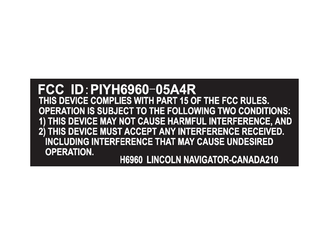
PIYH6960-05A4RWEST COAST
Mattel Asia Pacific Sourcing Ltd.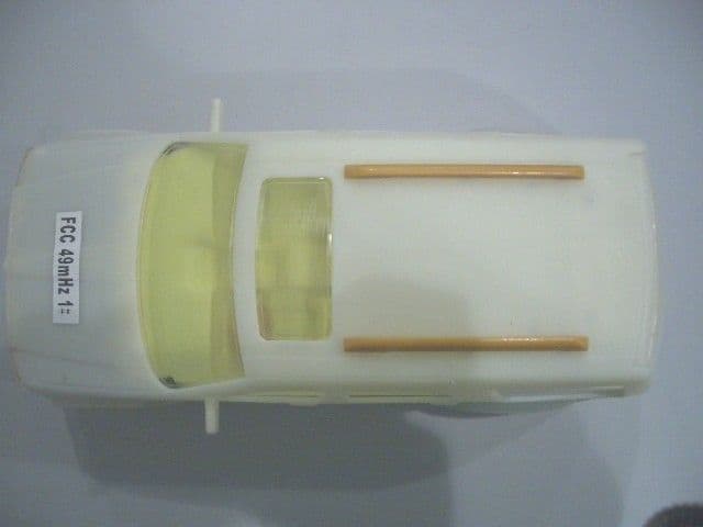
Click to zoom
Application Details
- Equipment Class
- CRR - Superregenerative Receiver
- Date of Grant
- May 24, 2005
- Application Purpose
- Original Equipment
- Date of Application
- May 24, 2005
- Equipment Note
- WEST COAST
- Frequency Range
- 49.86000000 - 49.86000000
- Country
- Hong Kong
Documents & Files
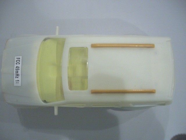
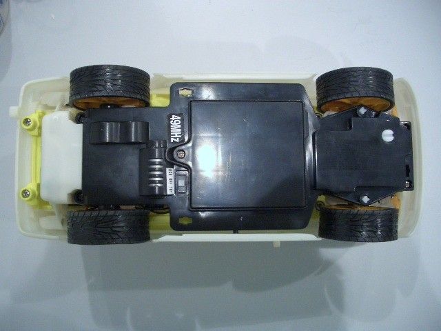
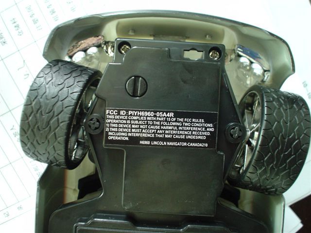
Document Text
Text extracted from the exhibit documents filed with the FCC. Open a document above to read the original.
Users Manual
I.CONTENTS/FEATURES Vehicle qSteering Adjuster wBattery Door e3 AA Try-me Batteries rON/OFF/Try-Me switch * This switch has three positions: IVehicle On: Vehicle runs with lights as you drive OVehicle OFF Ä Vehicle On: Activates 'try me' function with lights t Lights yTry-Me button-with lights Keep these instructions for future reference: they contain important information.IMPORTANT: Please read all “Consumer Information” before operating your vehicle. 6.0V R/C CAUTION:Surfaces may become hot and cause burns if electronics get wet. Do not operate vehicle through water or snow. H6958-0920 H6958-9993-S1 TYCO R/C SUPPORT Questions or problems with your product? DON’T RETURN IT TO THE STORE! Just call us for help. U.S. consumers may also register their products at this number. 1 888 557-TYCO (8926) ® tycorc.com w q e q B A Transmitter qAntenna wVehicle Controls eBattery Door w e q w e t t y A B r r III.BATTERY INSTALLATION Requires 6 AA Alkaline Batteries (2AA for transmitter and 4 AA for vehicle). Batteries included are for demon- stration purposes only. Vehicle 1. Use a screwdriver (not included) to unscrew the power clip cover screw, open the battery cover as shown. 2. Remove 3 "AA" batteries (included for Try-Me Lights ONLY) and replace with 4 new "AA" alkaline batteries (not included) with polarity (+/-) as shown inside the battery compartment. 3. Replace the battery door. Transmitter 1. Remove the battery cover as shown. 2. Install 2 AA alkaline batteries(not included) with polarity (+/-) as shown inside the battery compartment. 3. Replace the battery door. * Your transmitter is equipped with a special automatic ON battery-saving feature. Just turn your vehicle ON. Then push either transmitter control to run and control your vehicle. IV.CONSUMER INFORMATION Note to Adults: To ensure that the child’s play is both safe and fun, please review all operating instructions and safety rules with your child. Safety Tips • NEVER drive your vehicle on streets! They’re for real cars! • DO NOT pick up vehicle while in motion. • Keep fingers, hair and loose clothing away from the tires and the wheel hubs while the vehicle is switched ON. X CAUTION:To prevent entanglement, keep hair away from wheels. • Adult supervision is recommended when this vehicle is being operated. • To avoid accidental operation, remove all batteries when not in use. Always turn the vehicle OFF before removing batteries. BATTERY SAFETY INFORMATION In exceptional circumstances batteries may leak fluids that can cause a chemical burn injury or ruin your product. To avoid battery leakage: • Non-rechargeable batteries are not to be recharged. • Rechargeable batteries are to be removed from the product before being charged (if designed to be removable). • Rechargeable batteries are only to be charged under adult supervision (if designed to be removable). • Do not mix alkaline, standard (carbon-zinc), or rechargeable (nickel-cadmium) batteries. • Do not mix old and new batteries. • Only batteries of the same or equivalent type as recommended are to be used. • Batteries are to be inserted with the correct polarity. • Exhausted batteries are to be removed from the product. • The supply terminals are not to be short-circuited. • Dispose of battery (ies) safely. • Do not dispose of this product in a fire. The batteries inside may explode or leak. Battery Performance Note: For best performance use regular or high-performance alkaline batteries (where disposable batteries are called for). If your vehicle is supplied with standard (carbon-zinc) batteries for initial use and/or demonstration purposes, we recommend replacing them with alkaline batteries when necessary. Battery life may vary depending on battery brand. II.VEHICLE OPERATION FORWARDREVERSE RIGHT LEFT 1. When your vehicle starts to lose power, it may lose functions or performance. It's time for fresh batteries (or a recharge). Your vehicle's running time may change depending on your driving style. 2. Radio interference can make your vehicle run badly. Interference can be caused by other R/C vehicles running on the same frequency; electrical wires; large buildings; or CB radios. Try to stay away from these! 3. Point your transmitter antenna up - not down toward your vehicle. If your vehicle gets too far away, it won't work properly. If your transmitter has an antenna carry-loop feature, make sure the antenna is removed from the holder and straightened before operating. 4. Don’t drive your vehicle in sand or through water or snow. 5. Don’t store your vehicle near heat or in direct sunlight. Always turn switches OFF and remove all batteries for storage. V.QUICK TIPS SYMPTOM Vehicle runs slowly or will not run. Power indicator light on transmitter does not light. Erratic operation or only short range possible. Vehicle doesn’t work after going through water or snow. • PROBABLE CAUSE • Loose battery connection or vehicle switch not ON. • Weak or uncharged rechargeable NiCd battery. • Weak AA batteries (Power Clip) or transmitter battery. • Transmitter battery weak or not connected. • Radio interference likely. • Water in the electronics area. • CORRECTION • Check battery connector and vehicle switch. • Charge battery or replace. • Replace with fresh alkaline battery. • Check connections and replace battery if required. • Change location - see Point 2, “Quick Tips.” • Vehicle will take several hours to dry. Allow to dry thoroughly overnight before trying again. • Avoid driving in water or snow. TROUBLESHOOTING - PROBLEM? - SOLUTIONS 90-DAY LIMITED WARRANTY – TYCO® R/C PRODUCTS Mattel, Inc. warrants to the original consumer purchaser that this product will be free of defects in material and workmanship for ninety (90) days (unless specified in alternate warranties) from the date of purchase. Mattel will replace the product in the event of such a defect within the warranty period. In the event of a defect covered under this warranty, first call the toll-free number listed below. Many pro…
Text truncated - open the document above for the full version.
Operational Description
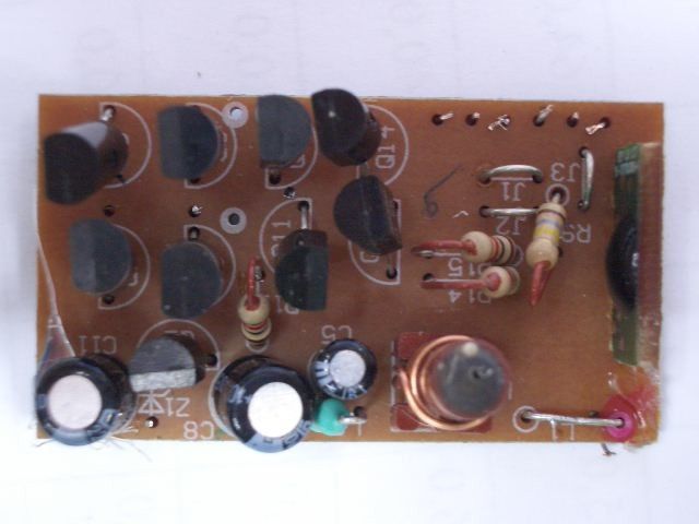
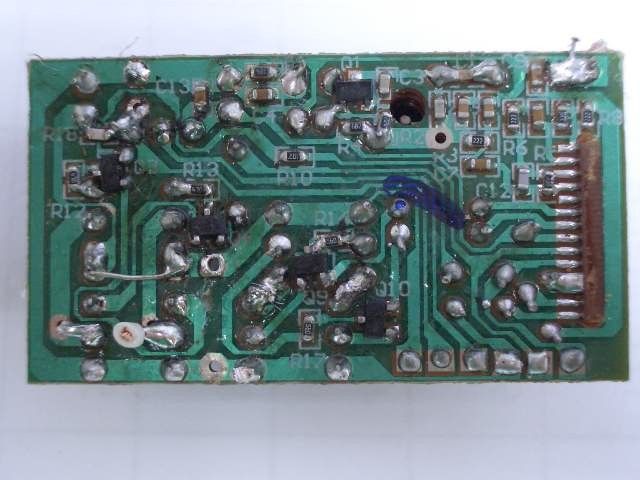
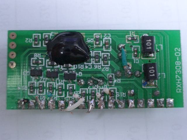
Mattel #H6960 West Coast RX 49. 860 MHz Receiver Operational Description The 6.0V West Coast RX is full function radio controlled toy car which has light,It operates on 6.0 volts supplied by four 1.5 volts alkaline AA batteries It is designed to operate on a single fixed frequency in the 49.82 ñ 49.90 MHz band. See the attached block diagram and schematic. The vehicle receiver receives and demodulates the AM transmitted signal from the transmitter, using a standard super-regenerative AM receiver/demodulator circuit comprised of ANT1, Q1, L2, L3,and associated passive components. L3 is a tunable core slug inductor that is used to tune the receiver for maximum sensitivity. The output of the AM receiver/demodulator is AC coupled to a high input impedance CMOS inverter is connected to the U1 decoder IC, it is biased into their linear region through C12, C14, C9, R4, R13, R6, R7 and function as amplify, filter and shape the data. After passing through the last inverter stage, the incoming waveform is a digitized enough to be fed into the IN1 pin for on-chip decoding. A Zener regulator circuit comprised of C11, C13, R3, D1, C8, C15, it supplied voltage VDD for the super-regenerative radio, decoder IC. Drive motor is controlled by the U1 decoder IC, low power switching transistors Q6, Q7, and a high power H-bridge comprised of Q4, Q5, Q8, Q9, The Steering Motor is controlled by the U1 decoder IC low power switching transistors Q12,Q14,and a high power H-bridge comprised of Q10,Q11,Q13,Q15, The light IC U2 is also triggered by the Forward and Reverse output of U1 decoder IC,it lights accordingly when controlling the car All tuning and verifications are performed by the manufacturer and there are no adjustments which can be made by the user. No external ground is required or used with this receiver.
Schematics
1234 A B C D 4 321 D C B A Title NumberRevisionSize A4 Date:6-May-2005 Sheet of File:E:\protel99\7308.DdbDrawn By: Q8 D882 Q6 D882 Q7 B772 Q5 B772 M1 Q3 2SC1623 Q4 2SC1623 R13 47 R12 47 Q14 8050 Q12 8050 Q13 8550 Q11 8550 M2 Q9 2SC1623 Q10 2SC1623 R17 56 R16 56 Q1 2SC2712Y R14 1K R11 1K R10 1K R15 1K L3 L2 3.3uH R2 220K C4 332 C2 2P C5 4.7uF C1 5P ANT C3 18P R4 6.8K C8 220uF R18 47 R1 430 C16 104 4.5V C13 104 MEISIDA TOYS H6960-1RX(49M) C6 103 Z1 3.9V C11 220uF Q2 9012 C15 104 1 2 4 5 6 7 8 9 10 11 12 13 14 G P R C 2 0 6 A C9 102 R9 180K R5 3.3M C12120 C7104 R3 2.2K C10 103 R6 2.2K C14 104 R7 3.3M R8 2.2K RF Enable Forwaurd Backwand VDD VCC GND SW-3D2P 1.5V T r y M e NORMAL OFF TRY ME NORMAL OFF TRY ME L4 6.8uH L5 6.8uH PDF created with pdfFactory trial version www.pdffactory.com
Schematics
1234 A B C D 4 321 D C B A Title NumberRevisionSize A4 Date:6-May-2005 Sheet of File:E:\protel99\7308.DdbDrawn By: C1 104 L1 100uH L2 100uH R1 68 R31K R21K R11 100 R12 100 R13 100 R14 100 D1 LED D2 LED D3 LED D4 LED Q2 2SC1623 Q4 2SC1623 R8 2.2K R9 2.2K R5 1 8 0 K C2 104 RF Enable VCC Backward Forward VDD GND Try Me Try Me C3 220uF S P C 1 0 0 2 4 A VDD PVDD VSS PVSS RESET TESTAUDN AUDP ROSE IOD0 IOD1 IOD2 IOD3 IOD4 IOD5 IOD6 IOD7 MEISIDA TOYS H6960-2 R41K PDF created with pdfFactory trial version www.pdffactory.com
Test Report
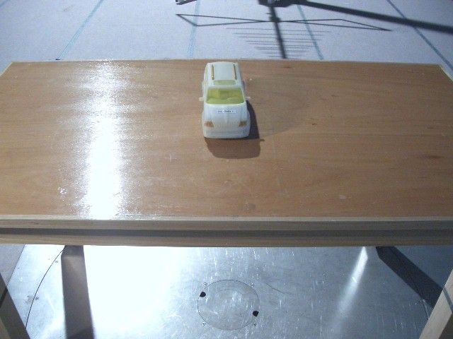
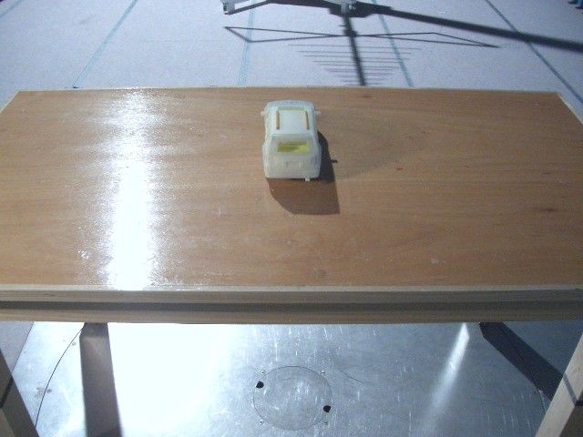
TEST REPORT Report No. : AF010608-001 Date : 2005 May 24 For and on behalf of CMA Testing and Certification Laboratories Authorized Signature : Page 1 of 11 Danny Chui EMC Engineer - EL. Division FCC ID : PIYH6960-05A4R This document shall not be reproduced either in full or in part except with written approval by the Authorized Representative of CMA Testing. Room 1302, Yan Hing Centre, 9-13 Wong Chuk Yeung St.., Fo Tan, Shatin, Hong Kong. Tel: (852) 2698 8198 Fax: (852) 2695 4177 E-mail: [email protected] Web Site: http://www.cmatcl.com Application No. : LF206763(2) Client : Mattel Asia Pacific Sourcing Limited 13/F., South Tower, World Finance Centre, Harbour City, Tsimshatsui, Kowloon, Hong Kong. Sample Description : One(1) submitted sample stated to be Tyco RC West Coast of Model No. H6960 Rating : 4 x 1.5V AA size battery No. of submitted sample : Two (2) piece(s)*** Date Received : Test Period : Test Requested : Test Method : Test Result : Conclusion : 2005 May 19 2005 May 19 – 2005 May 23 FCC Part 15 Certification FCC Rules and Regulations Part 15 – July 2004 ANSI C63.4 – 2003 See attached sheet(s) from page 2 to 11. The submitted sample was found to comply with requirement of FCC Part 15 Subpart B. TEST REPORT Report No. : AF010608-001 Date : 2005 May 24 Page 2 of 11 FCC ID : PIYH6960-05A4R This document shall not be reproduced either in full or in part except with written approval by the Authorized Representative of CMA Testing. Room 1302, Yan Hing Centre, 9-13 Wong Chuk Yeung St.., Fo Tan, Shatin, Hong Kong. Tel: (852) 2698 8198 Fax: (852) 2695 4177 E-mail: [email protected] Web Site: http://www.cmatcl.com Table of Contents 1 General Information ..................................................................................................................... 3 1.1 General Description ............................................................................................................... 3 1.2 Location of the test site.......................................................................................................... 4 1.3 List of measuring equipment ................................................................................................. 5 2 Description of the radiated emission test ..................................................................................... 6 2.1 Test Procedure ....................................................................................................................... 6 2.2 Test Result ............................................................................................................................. 6 2.3 Radiated Emission Measurement Data.................................................................................. 7 3 Description of the Line-conducted Test .......................................................................................8 3.1 Test Procedure ....................................................................................................................... 8 3.2 Test Result ............................................................................................................................. 8 3.3 Graph and Table of Conducted Emission Measurement Data .............................................. 8 4 Photograph ................................................................................................................................... 9 4.1 Photographs of the Test Setup for Radiated Emission and Conduction Emission ................ 9 4.2 Photographs of the External and Internal Configurations of the EUT .................................. 9 5 Supplementary document ............................................................................................................ 10 5.1 Bandwidth............................................................................................................................ 10 5.2 Duty Cycle ............................................................................................................................ 10 6 Appendices .................................................................................................................................. 11 TEST REPORT Report No. : AF010608-001 Date : 2005 May 24 Page 3 of 11 FCC ID : PIYH6960-05A4R This document shall not be reproduced either in full or in part except with written approval by the Authorized Representative of CMA Testing. Room 1302, Yan Hing Centre, 9-13 Wong Chuk Yeung St.., Fo Tan, Shatin, Hong Kong. Tel: (852) 2698 8198 Fax: (852) 2695 4177 E-mail: [email protected] Web Site: http://www.cmatcl.com 1 General Information 1.1 General Description The equipment under test (EUT) is a superregenerative receiver for Tyco RC West Coast. Operating at 49.860MHz which is controlled by a LRC circuit. The EUT is powered by 4 x 1.5V AA size battery. When it power on, it can receive difference radio signal and go difference direction with LED flashing. The brief circuit description is listed as follows : - Q1 and associated circuit act as superregenerative circuit. - GPRC206A and associated circuit act as decoder. - Q3 ~ Q8 and associated circuit act as control motor M1. - Q9 ~ Q14 and associated circuit act as control motor M2. - Q2 and associated circuit act as voltage regulator. - Q2(2SC1623), Q4(2SC1623) and associated circuit act as control LED. TEST REPORT Report No. : AF010608-001 Date : 2005 May 24 Page 4 of 11 FCC ID : PIYH6960-05A4R This document shall not be reproduced either in full or in part except with written approval by the Authorized Representative of CMA Testing. Room 1302, Yan Hing Centre, 9-13 Wong Chuk Yeung St.., Fo Tan, Shatin, Hong Kong. Tel: (852) 2698 8198 Fax: (852) 2695 4177 E-mail: [email protected] Web Site: http://www.cmatcl.com 1.2 Location of the test site Radiated emissions measurements are investigated and taken pursuant to the procedures of ANSI C63.4 – 2003. A Semi-Anechoic Chamber Testing Site is set up for investigation and located at : Gro…
Text truncated - open the document above for the full version.
Contact Information
Applicant
Joule Mak(Director, Electronic Engineering)
Test Firm
CMA Industrial Development Foundations LimitedAndrew Wong
Technical Specifications
| # | Rule Parts | Frequency Range | Power Output |
|---|---|---|---|
| 1 | 15B | 49.86 MHz - 49.86 MHz | - |
Other Applications from Mattel Asia Pacific Sourcing Ltd.
PIY-HTX00-24-A5T
Jan 17, 2024Fisher-Price Link Squad Jam & Count Panda
Equipment Class
DXX - Part 15 Low Power Communication Device TransmitterPIY-HTX03-24-A5T
Jan 17, 2024Fisher-Price Link Squad A to Z Yak
Equipment Class
DXX - Part 15 Low Power Communication Device TransmitterPIY-HTX04-24-A5T
Jan 17, 2024Fisher-Price Link SquadBop & Groove Tiger
Equipment Class
DXX - Part 15 Low Power Communication Device TransmitterPIY-HTW99-24-A5T
Jan 17, 2024Fisher-Price Link Squad Opposites Fox
Equipment Class
DXX - Part 15 Low Power Communication Device TransmitterPIY-HTX01-24-A5T
Jan 17, 2024Fisher-Price Link Squad Crawl n Colors Chameleon
Equipment Class
DXX - Part 15 Low Power Communication Device Transmitter