PIYJ2358-07A1TRadar Gun
Mattel Asia Pacific Sourcing Ltd.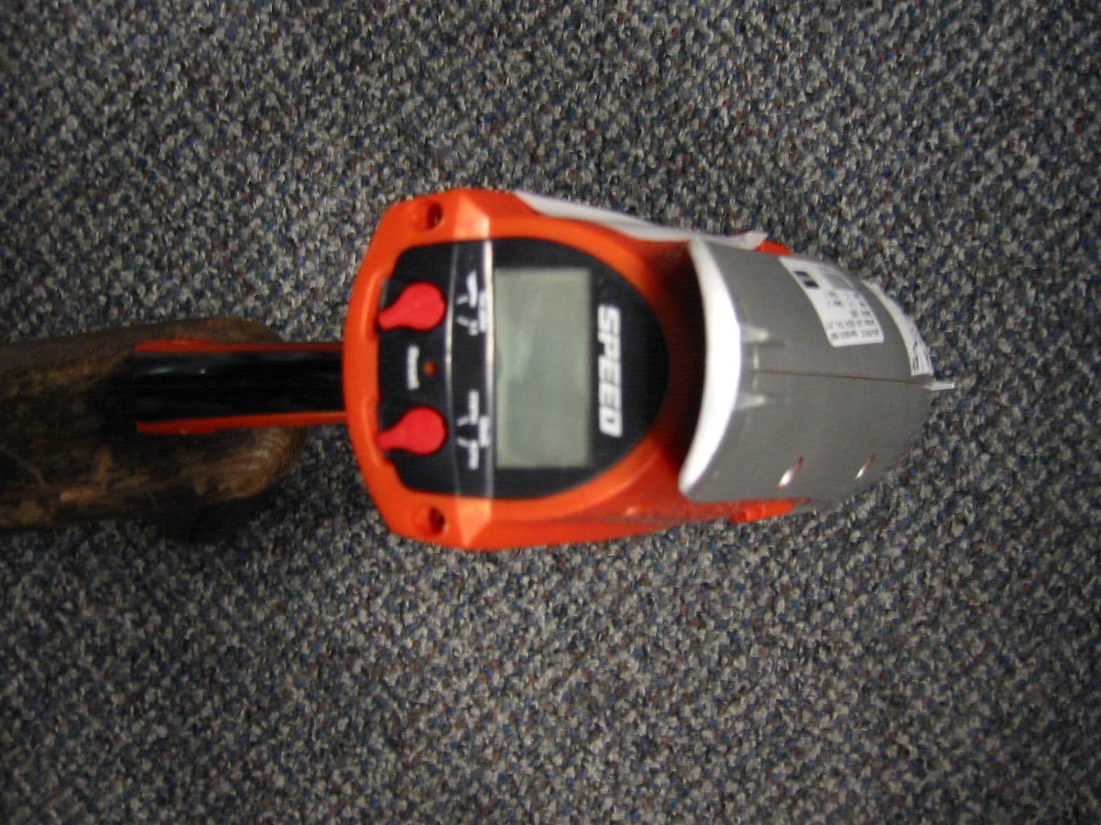
Click to zoom
Application Details
- Equipment Class
- FDS - Part 15 Field Disturbance Sensor
- Date of Grant
- Jul 23, 2007
- Application Purpose
- Original Equipment
- Date of Application
- Jul 23, 2007
- Equipment Note
- Radar Gun
- Frequency Range
- 10525.00000000 - 10525.00000000
- Country
- Hong Kong
Documents & Files
Document Text
Text extracted from the exhibit documents filed with the FCC. Open a document above to read the original.
Users Manual
J2358-0920 G1 SIZE: 5.5x13” COLOR: 1C+1C FrontJ2358-0920 G1 SIZE: 5.5x13” COLOR: 1C+1C Back 1 4 2 3 6 5 CONTENTS / FEATURES 1. SCALE SWITCH 2. UNIT SWITCH 3. RESET BUTTON 4. LCD 5. TRIGGER (Activates radar) 6. BATTERY COVER BATTERY INSTALLATION/REPLACEMENT Unscrew the battery cover with a Phillips-head screwdriver (not included). Insert 4 "AAA" (LR03) alkaline batteries (not included) in the orientation shown. Replace the battery cover and tighten screw. For best performance, use only alkaline batteries. If the unit does not function properly, a bent paper clip should be used (by an adult only) to depress the reset button. When the batteries are low, the digital readout screen will flash a broken battery symbol, indicating it is time to change the batteries. BATTERY SAFETY INFORMATION In exceptional circumstances batteries may leak fluids that can cause a chemical burn injury or ruin your product. To avoid battery leakage: • Non-rechargeable batteries are not to be recharged. • Rechargeable batteries are to be removed from the product before being charged (if designed to be removable). • Rechargeable batteries are only to be charged under adult supervision (if designed to be removable). • Do not mix alkaline, standard (carbon-zinc), or rechargeable (nickel-cadmium) batteries. • Do not mix old and new batteries. • Only batteries of the same or equivalent type as recommended are to be used. • Batteries are to be inserted with the correct polarity. • Exhausted batteries are to be removed from the product. • The supply terminals are not to be short-circuited. • Dispose of battery(ies) safely. • Do not dispose of this product in a fire. The batteries inside may explode or leak. B TO OPERATE: Your radar gun has a digital readout screen which will show instantaneous real speed or Hot Wheels® 1/64th scale speed of objects coming toward you or moving away. What does Hot Wheels® scale speed mean? Hot Wheels® cars are 1/64th the size of a real car. So if a Hot Wheels® car goes 10 MPH / 16 KPH calculate: 10 MPH X 64 = 640 MPH or 16 KPH x 64 = 1024 KPH! INSTRUCTIONS 7+ ® J2358-0920 G1 ® COMPLIANCE WITH FCC REGULATIONS (VALID IN U.S.ONLY) This device complies with part 15 of the FCC Rules. Operation is subject to the following two conditions: (1) This device may not cause harmful interference, and (2) this device must accept any interference received, including interference that may cause undesired operation. NOTE: This equipment has been tested and found to comply with the limits for a Class B digital device, pursuant to Part 15 of the FCC Rules. These limits are designed to provide reasonable protection against harmful interference in a residential installation. This equipment generates, uses and can radiate radio frequency energy and, if not installed and used in accordance with the instructions, may cause harmful interference to radio communications. However, there is no guarantee that interference will not occur in a particular installation. If this equipment does cause harmful interference to radio or television reception, which can be determined by turning the equipment off and on, the user is encouraged to try to correct the interference by one or more of the following measures: • Reorient or relocate the receiving antenna. • Increase the separation between the equipment and receiver. • Consult the dealer or an experienced radio/TV technician for help. NOTE: Changes or modifications not expressively approved by the manufacturer responsible for compliance could void the user’s authority to operate the equipment. © 2006 Mattel, Inc. All Rights Reserved. Mattel, Inc., 333 Continental Blvd.,El Segundo, CA 90245 U.S.A. Consumer Relations 1-800-524-8697 service.mattel.com. Mattel U.K. Ltd., Vanwall Business Park, Maidenhead SL6 4UB. Helpline 01628500303. Mattel Australia Pty., Ltd., Richmond, Victoria. 3121.Consumer Advisory Service - 1300 135 312. Mattel East Asia Ltd., Room 1106, South Tower, World Finance Centre, Harbour City, Tsimshatsui, HK, China. Diimport & Diedarkan Oleh: Mattel SEA Ptd Ltd.(993532-P) Lot 13.5, 13th Floor, Menara Lien Hoe, Persiaran Tropicana Golf Country Resort, 47410 PJ. Tel:03-78803817, Fax:03-78803867. 1:1 KPH MPH Reset A Please note: For most accurate read, objects must be moving directly towards or away from the radar gun. Point the radar gun at a 25-45 degree angle to either the front or rear of the vehicle as it is traveling on the track. Make sure the radar gun is no more than 1.5 feet (.45 m) away from the Hot Wheels® car being measured. Protect the environment by not disposing of this product with household waste [2002/96/EC]. Check your local authority for recycling advice and facilities. Hot Wheels® 1:64 1:64 HOT WHEELS ® SCALE MODE 1:1 SCALE MODE • Do NOT use in or near the street. • The MAXIMUM measuring/responding distance is approximately 39 feet (12 m). Please keep these instructions for future reference as they contain important information. • Pressing and holding the trigger will show the current speed on the screen. • Releasing the trigger will show the MAX detected speed on the screen for approximately 30 seconds. • Pressing and holding the trigger again will reset the digital readout to 0 and the speed of the next object will be measured. • Pressing and holding the trigger will show the current speed on the screen. • Releasing the trigger will show the MAX detected speed on the screen for approximately 30 seconds. • Pressing and holding the trigger again will reset the digital readout to 0 and the speed of the next object will be measured.
External Photos
Top View Bottom View Side View 1 Side View 2 Front View Back View Isometric View 1 Isometric View 2
Internal Photos
Assembly View Radar Tube Assembly View Radar Tube View, One End Removed Display Board Back Display Board Back Display Removed Display Board Front Radar Board Front Radar Board Back
Test Report
Report Number 3117002BOX-001 Page 2 of 21 1.0 Job Description 1.1 Client Information This EUT has been tested at the request of: Company: Intertek ETL SEMKO – Hong Kong Co #68 Labtest Hong Kong Ltd. 6/F Garment Centre 576 Castle Peak Road Kowloon, Hong Kong Contact: Brandon Chuk Telephone: Fax: Email: 2173 8503 2371 0521 [email protected] 1.2 Equipment Under Test Equipment Type: 10.525 GHz Toy Radar Gun Model Number(s): J2358 Serial number(s): A Manufacturer: Lung Cheong Toys Limited EUT receive date: 01/31/2007 EUT received condition: Prototype in good condition Test start date: 02/26/2007 Test end date: 02/28/2007 1.3 Test Plan Reference: Tested according to the standards listed, RSS-Gen Issue 1 September 2005, and ANSI C63.4:2003. 1.4 Test Configuration 1.4.1 Block Diagram Toy Radar Gun Turntable Report Number 3117002BOX-001 Page 3 of 21 1.4.2. Cables: Cable Shielding Connector Length (m) Qty. None 1.4.3. Support Equipment: Name: Model No.: Serial No.: None 1.5 Mode(s) of Operation: The EUT was transmitting continuously during testing, and was operated from fresh batteries at 6VDC. Report Number 3117002BOX-001 Page 4 of 21 2.0 Test Summary TEST STANDARD RESULTS FCC Part 15 Subpart C 15.245 Industry Canada’s RSS-210 Issue 6 September 2005 Annex 7 SUB-TEST TEST PARAMETER COMMENT Fundamental Field Strength and Radiated Spurious Emissions FCC 15.109, 15.205, 15.209, 15.245 RSS-210 Annex 7, RSS-Gen Section 6 Fundamental field strength shall not exceed 2500 mV/m (128 dBuV/m) at 3 meters. Harmonic emission field strength shall not exceed 25 mV/m (88.5 dBuV/m) at 3 meters, unless in a restricted band above 17.7 GHz, in which case the harmonic field strength shall not exceed 7.5 mV/m (77.5 dBuV/m). All other emissions must be attenuated at least 50 dB below the level of the fundamental or below 15.209 and RSS-210 Table 2 limits, whichever is the lesser attenuation. Receiver Spurious Emissions must not exceed the RSS- Gen Section 6 Table 1 limits and the FCC Part 15 Subpart B Class B limits. Pass Radiated Spurious Emissions, 40 – 53 GHz FCC 15.205, 15.209, 15.245 No RSS-210 Requirement Harmonic emission field strength shall not exceed 25 mV/m (88.5 dBuV/m) at 3 meters, unless in a restricted band above 17.7 GHz, in which case the harmonic field strength shall not exceed 7.5 mV/m (77.5 dBuV/m). All other emissions must be attenuated at least 50 dB below the level of the fundamental or below 15.209 limits, whichever is the lesser attenuation. Pass Occupied Bandwidth RSS-Gen Section 4.4 The 20 dB bandwidth must be recorded. No Requirements Duty Cycle FCC 15.35(c) RSS-Gen Section 4.3 Fundamental and harmonic emissions levels can be adjusted by a duty cycle correction factor. No Requirements REVISION SUMMARY – The following changes have been made to this Report: Date Project No. Project Handler Page(s) Item Description of Change Report Number 3117002BOX-001 Page 5 of 21 3.0 Sample Calculations The field strength is calculated by adding the Antenna Factor and Cable Factor, and subtracting the Amplifier Gain (if any) from the measured reading. The basic equation with a sample calculation is as follows: FS = RA + AF + CF - AG Where FS = Field Strength in dBμV/m RA = Receiver Amplitude (including preamplifier) in dBμV CF = Cable Attenuation Factor in dB AF = Antenna Factor in dB AG = Amplifier Gain in dB In the following table(s), the reading shown on the data table reflects the preamplifier gain. An example for the calculations in the following table is as follows. Assume a receiver reading of 52.0 dBμV is obtained. The antenna factor of 7.4 dB and cable factor of 1.6 dB is added. The amplifier gain of 29 dB is subtracted, giving a field strength of 32 dBμV/m. This value in dBμV/m was converted to its corresponding level in μV/m. RA = 52.0 dBμV AF = 7.4 dB/m CF = 1.6 dB AG = 29.0 dB FS = 32 dBμV/m Level in μV/m = [10( 32 dBμV/m)/20] = 39.8 μV/m The following is how net line-conducted readings were determined: NF = RF + LF + CF + AF Where NF = Net Reading in dBμV RF = Reading from receiver in dBμV LF = LISN Correction Factor in dB CF = Cable Correction Factor in dB AF = Attenuator Loss Factor in dB To convert from dBμV to μV or mV the following was used: UF = 10 (NF / 20) where UF = Net Reading in μV Example: NF = RF + LF + CF + AF = 28.5 + 0.2 + 0.4 + 20.0 = 49.1 dBμV UF = 10 (48.1 dBμV / 20) = 254 μV/m Report Number 3117002BOX-001 Page 6 of 21 3.1 Measurement Uncertainty Compliance of the product is based on the measured value. However, the measurement uncertainty is included for informational purposes. The expanded uncertainty (k = 2) for radiated emissions from 30 to 1000 MHz has been determined to be: ±3.5 dB at 10m, ±3.8 dB at 3m The expanded uncertainty (k = 2) for mains conducted emissions from 150 kHz to 30 MHz has been determined to be: ±2.6 dB The expanded uncertainty (k = 2) for telecom port conducted emissions from 150 kHz to 30 MHz has been determined to be: ±3.2 for ISN and voltage probe measurements ±3.1 for current probe measurements Report Number 3117002BOX-001 Page 7 of 21 3.2 Site Description Test Site(s): 2 Our OATS are 3m and 10m sheltered emissions measurement ranges located in a light commercial environment in Boxborough, Massachusetts. They meet the technical requirements of ANSI C63.4-2003 and CISPR 22:1993/EN 55022:1994 for radiated and conducted emission measurements. The shelter structure is entirely fiberglass and plastic, with outside dimensions of 33 ft x 57 ft. The structure resembles a quonset hut with a center ceiling height of 16.5 ft. The testing floor is covered by a galvanized sheet metal groundplane that is earth-grounded via copper rods around the perimeter of the site. The joints between individual metal sheets are bridged with a 2 inch wide metal strips to provide low RF impedance contact throughout. The sheets are screwed in place with stainless steel, round-head screws every three inches. Site illumination and HVAC are provided from beneath the ground…
Text truncated - open the document above for the full version.
Contact Information
Applicant
Joule Mak(Director, Electronic Engineering)
Technical Contact
Intertek Testing Services Hong Kong Ltd.Anthony Chan
[email protected](852)2173-8517
2/F., Garment Centre, · Kowloon · Hong Kong
Non-Technical Contact
Intertek Testing Services Hong Kong Ltd.Anthony Chan
[email protected](852)2173-8517
Test Firm
Intertek Testing Services Hong KongBilly Chow
Technical Specifications
| # | Rule Parts | Frequency Range | Power Output |
|---|---|---|---|
| 1 | 15.245 | 10.53 GHz - 10.53 GHz | - |
Other Applications from Mattel Asia Pacific Sourcing Ltd.
PIY-HTX00-24-A5T
Jan 17, 2024Fisher-Price Link Squad Jam & Count Panda
Equipment Class
DXX - Part 15 Low Power Communication Device TransmitterPIY-HTX03-24-A5T
Jan 17, 2024Fisher-Price Link Squad A to Z Yak
Equipment Class
DXX - Part 15 Low Power Communication Device TransmitterPIY-HTX04-24-A5T
Jan 17, 2024Fisher-Price Link SquadBop & Groove Tiger
Equipment Class
DXX - Part 15 Low Power Communication Device TransmitterPIY-HTW99-24-A5T
Jan 17, 2024Fisher-Price Link Squad Opposites Fox
Equipment Class
DXX - Part 15 Low Power Communication Device TransmitterPIY-HTX01-24-A5T
Jan 17, 2024Fisher-Price Link Squad Crawl n Colors Chameleon
Equipment Class
DXX - Part 15 Low Power Communication Device Transmitter