PIYJ6849-05A2T1:18 HURRICANE
Mattel Asia Pacific Sourcing Ltd.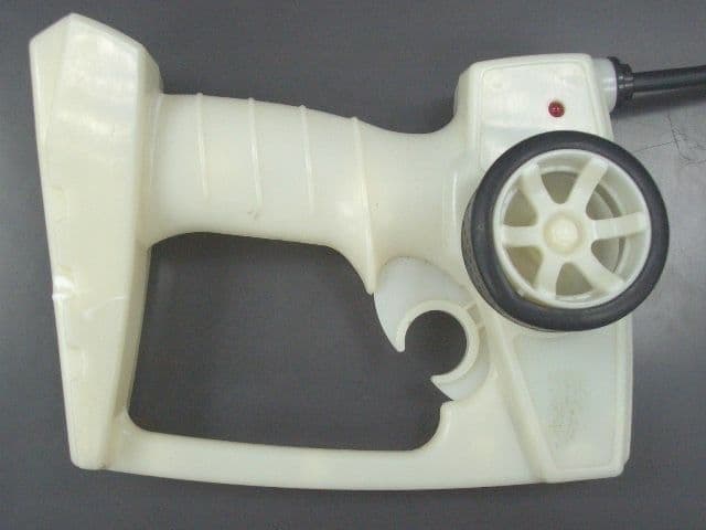
Click to zoom
Application Details
- Equipment Class
- DXX - Part 15 Low Power Communication Device Transmitter
- Date of Grant
- Nov 06, 2005
- Application Purpose
- Original Equipment
- Date of Application
- Nov 06, 2005
- Equipment Note
- 1:18 HURRICANE
- Frequency Range
- 27.14500000 - 27.14500000
- Country
- Hong Kong
Documents & Files
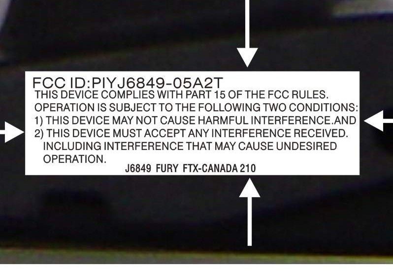
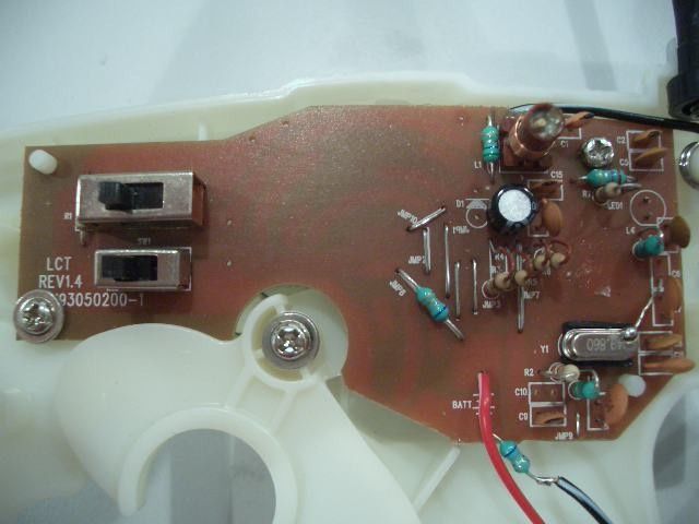
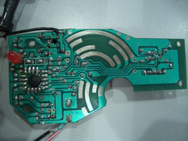
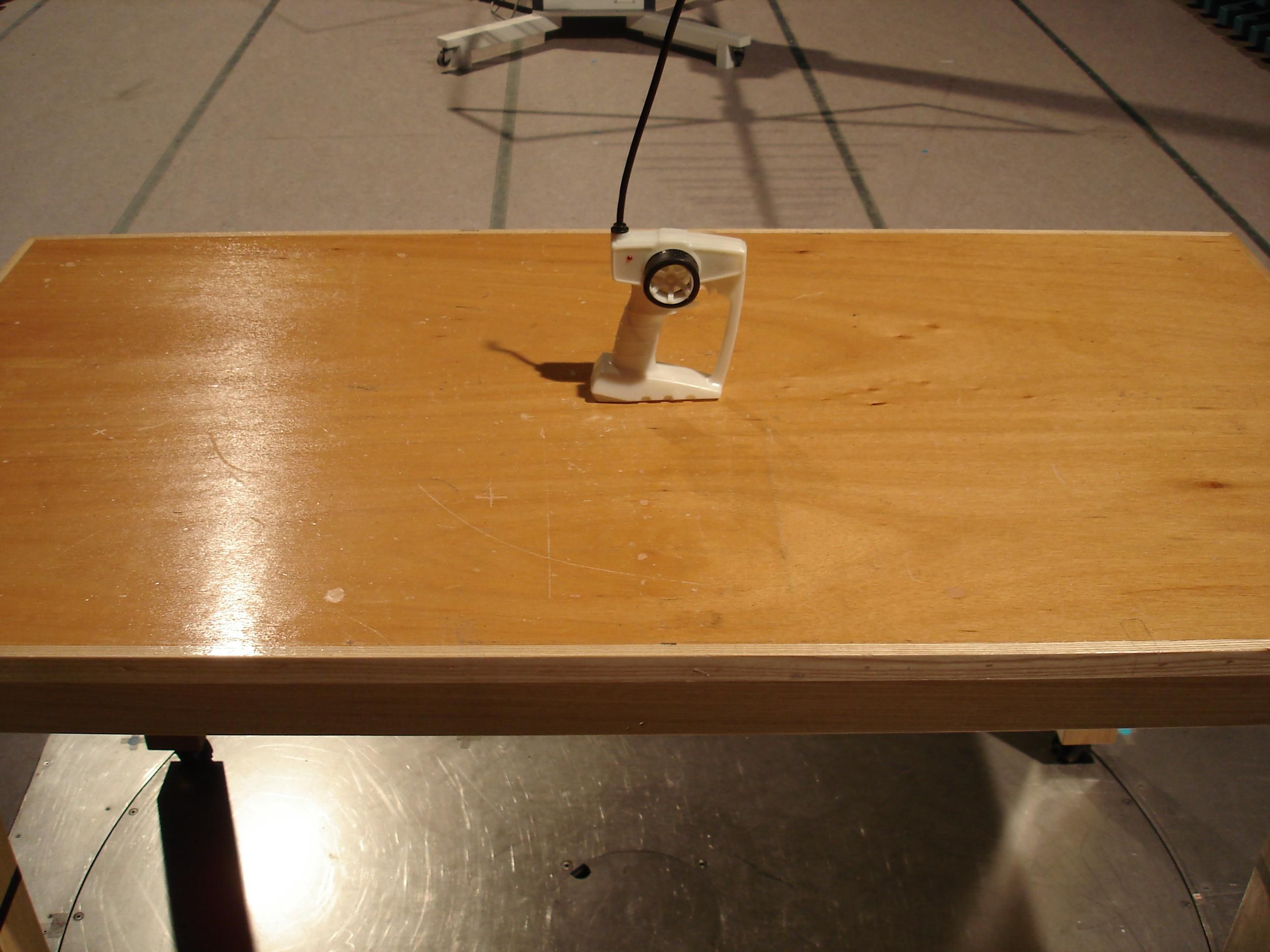
Document Text
Text extracted from the exhibit documents filed with the FCC. Open a document above to read the original.
Users Manual
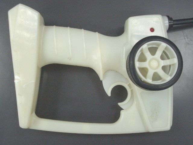
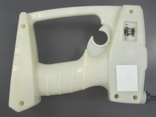
Hot Wheels ® R/C SUPPORT Questions or problems with your product? DON’T RETURN IT TO THE STORE! Just call us for help. U.S. consumers may also register their products at this number. 1-888-557-8926 XCAUTION:Surfaces may become hot and cause burns if electronics get wet. Do not operate vehicle through water or snow. Keep these instructions for future reference as they contain important information. IMPORTANT: Please read all “Consumer Information” before operating your vehicle. I. CONTENTS/ FEATURES Vehicle Transmitter Vehicle A Antenna * You will need to slip the loose antenna wire into the provided tube (it looks like a straw). Then push the straw (with wire already enclosed) firmly into the cylindrical opening on the chassis. B Multi-channel selector switch * Please see the “Multi-channel Feature” Section for more information. C Steering adjuster * Turn with a screwdriver (not included) to keep vehicle running straight. D ON(I)/OFF(O) switch E Battery door F AA Battery adapter Transmitter q Antenna w LED indicator(Light that indicates when your transmitter is turned on or off). e Steering knob: left / right control r Trigger: forward / reverse control t Multi-channel selector switch Please see the “Multi-channel Feature” Section for more information. y ON(I)/OFF(O) switch u Battery door * Just turn your vehicle ON. Then pull the trigger and you will be able to run and control your vehicle. * Pull trigger all the way back for that extra punch of power. 1 2 3 I O I O 1 2 3 1 2 3 I O 1 2 3 I O A Asst.H9305 J6849-0920 1 2 3 I O I O 1 2 3 1 2 3 I O 1 2 3 I O q w e r ® XCAUTION:To prevent entanglement, keep hair away from wheels. 1 2 3 I O I O 1 2 3 1 2 3 I O 1 2 3 I O t y u 1 2 3 I O I O 1 2 3 1 2 3 I O 1 2 3 I O D C B E F II. VEHICLE OPERATION * If your vehicle doesn’t move when you use the trans- mitter there’s a good chance your vehicle’s battery is ready for a recharge. III. MULTI-CHANNEL FEATURE • Your vehicle features the advanced Multi-channel system. This system lets you race your vehicle head-to- head – against up to two of your friends with the same vehicle (up to 6 drivers total with vehicles of the same assortment) – without any radio interference from your friends’ transmitters or vehicles. You must be racing against another Multi-channel-equipped vehicle for this feature to work. • There’s one Multi-channel selector switch on your vehicle chassis, and another one on your transmitter. The vehicle switch has 3 positions: one for each Multi- channel setting. The transmitter switch has 3 positions: one for each Multi- channel setting, plus an OFF position. • For successful operation, the vehicle switch and the transmitter switch must be set to the same Multi-channel setting. When you’re driving by yourself, you can set the switches to any of the 3 Multi-channel settings (as long as they match). • When you want to race head-to-head, just make sure that each driver (up to 6 drivers total) has a vehicle and transmitter set to a different Multi-channel setting. * To operate your vehicle, just turn the vehicle ON; then set the transmitter switch to the desired Multi-chan- nel setting. Push any transmitter control and you will be able to run and control your vehicle. * You must be racing against another Multi-channel- equipped vehicle for this feature to work. A non- Multi-channel vehicle, running on the same frequency as your vehicle, may interfere with operation of your vehicle. If you are racing against a non-Multi-channel vehicle, make sure that vehicle operates on a fre- quency different from yours. * If you need to change the Multi-channel setting, first make sure that your vehicle is turned OFF. Change the Multi-channel switch position as desired on both the transmitter AND the vehicle. Then turn your vehicle back ON for more racing action. NOTE: Make certain you’re not pressing a transmitter control while changing selector switch position. 1 2 3 1 2 3 RIGHT RIGHT RIGHT RIGHT FORWARDREVERSELEFTRIGHT IV. BATTERY INSTALLATION Note: Your vehicle can be used with a Tyco® R/C 9.6V NiCd battery pack or 6 AA alkaline batteries. Requires a Tyco® R/C 9.6V NiCd battery pack or 6 AA alkaline batteries for vehicle and 2 AA alkaline batteries for transmitter. * Though your Fury FTX TM can run on both 9.6V or 6 x AA batteries it will run up to 30% faster when using a 9.6V rechargeable battery. Vehicle 9.6V NiCd battery pack 1. Use a screwdriver (not included) to unscrew the battery cover. 2. Unscrew and remove the AA battery adapter. Store in a safe place for later usage. 3. Insert the 9.6V NiCd battery pack (not included), with polarity (+/-) as shown inside the battery compartment . 4. Plug the wire connector into the battery compartment as shown. 5. Replace the battery cover. 6 AA alkaline batteries 1. Use a screwdriver (not included) to unscrew the battery cover. 2. Make sure the AA battery adapter is firmly in place. If it’s not, position the adapter in the box and fasten it with the screw. 3. Insert the 6 AA batteries (not included), with polarity (+/-) as shown inside the battery compartment . 4. Replace the battery cover. Transmitter 1. Remove the battery cover as shown. 2. Install 2 AA batteries (not included), with polarity (+/-) as shown inside the battery compartment. 3. Replace the battery cover. * If the transmitter’s LED indicator does not light when the transmitter is switched ON, it’s time to replace the transmitter batteries. Simply install fresh batteries as described above. ; V. QUICK TIPS 1. The best jumps are the ones where the rear wheels hit the ground first. It’s important to give your Fury FTX TM vehicle just enough power as it leaves the ramp. Too much power and your nose will rise abruptly, too little and you’ll land on the front wheels. When you do land, make sure all four wheels are on the ground before you accelerate. If you don’t you may cause a wheelie, which may look really cool, but you’ll lose time. 2. The Fury FTX TM was meant to fly high and land soft but …
Text truncated - open the document above for the full version.
Operational Description
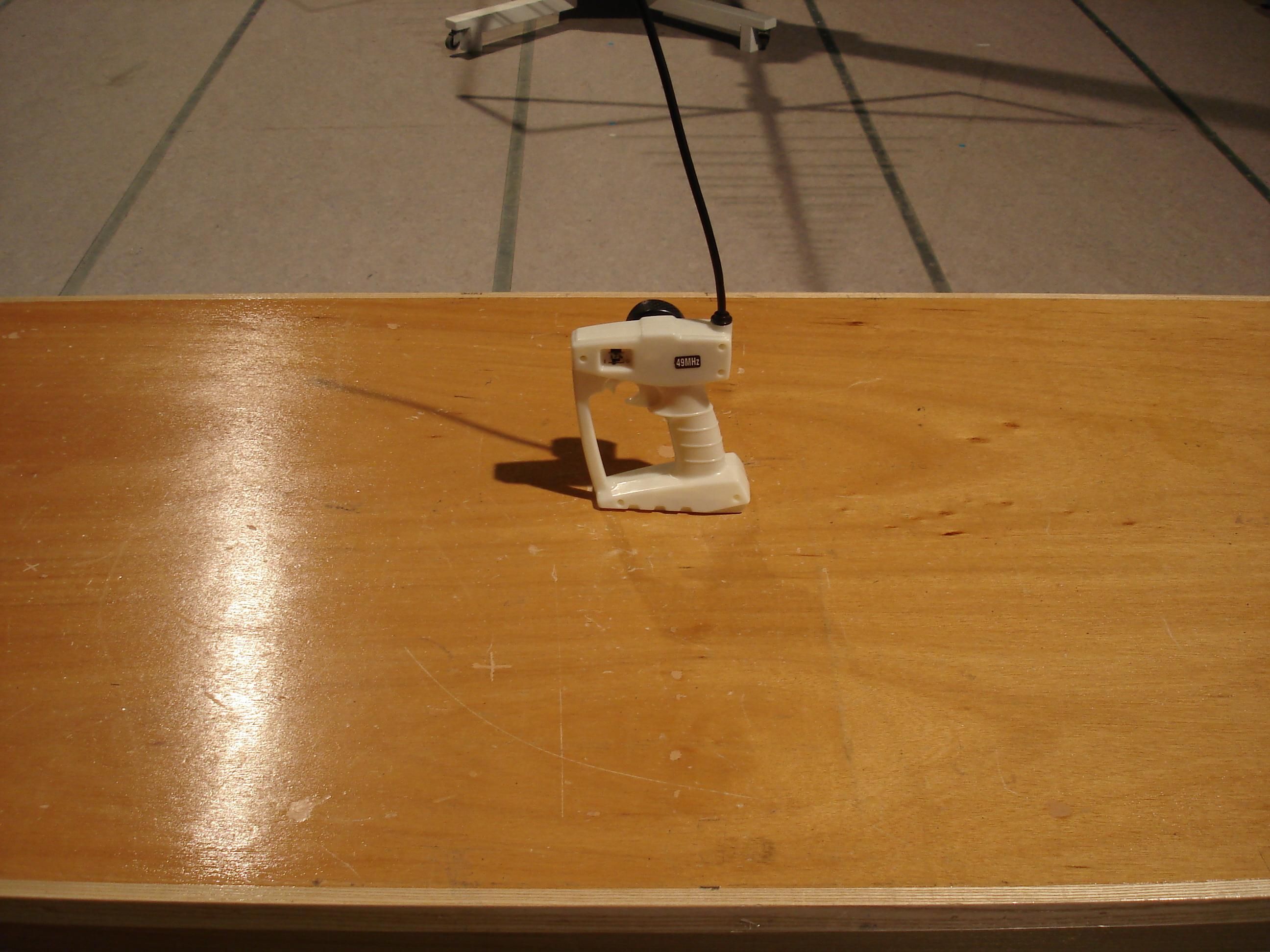
27.145MHz transmitter operational description of hurricane The transmitter send out 27.105MHz ~27.185MHz signal of high frequency to control the cat move ,which supply voltage is 3.0volts with two batteries (size AA). Please consult with added block diagram and schematic . When the user pulls the trigger or pulls the whirlabout (schematic presents with SW2~SW11),the high voltage signal enters into IC (W55RF27T3B) .these signal is processed by IC and sent out through ANT-6 pin of IC .Y1,R2,C8,C9 makes up of oscillator ,which generated base oscillatory signal .The signal of R,LF,B,F1 and F2 come by L4,C5,L3,L1,C1 and fixed 27.145MHz of high frequency, is sent out. In the IC inner , the input signal need be enlarged and this function need voltage too . The voltage is supplied by the power through L2 ,C15 . A LED acts as a power ñon indicator . All tuning and verifications are performed by the manufacturer and there are no adjustment which can be made by the user .No external ground is required or used with this transmitter .
Schematics
H9305TX27M.sch-1 - Fri Oct 21 21:19:46 2005
Test Report
TEST REPORT Report No. : AF025512-001 Date : 2005 November 07 Page 1 of 11 FCC ID: PIYJ6849-05A2T This document shall not be reproduced either in full or in part except with written approval by the Authorized Representative of CMA Testing. Room 1302, Yan Hing Centre, 9-13 Wong Chuk Yeung St.., Fo Tan, Shatin, Hong Kong. Tel: (852) 2698 8198 Fax: (852) 2695 4177 E-mail: [email protected] Web Site: http://www.cmatcl.com Application No. : LF219572(4) Client : Mattel Asia Pacific Sourcing Limited 13/F., South Tower, World Finance Centre, Harbour City, Tsimshatsui, Kowloon, Hong Kong Sample Description : One(1) submitted sample(s) stated to be 1:18 Hurricane of Model No. H9305 Rating : 2 x 1.5V AA size batteries No. of submitted sample : Three (3) piece(s) Date Received : 2005 October 05 Test Period : 2005 October 10 – 2005 November 04 Test Requested : FCC Part 15 Certification. Test Method : FCC Rules and Regulations Part 15 – July 2004 ANSI C63.4 – 2003 Test Result : See attached sheet(s) from page 2 to 11. Conclusion : The submitted sample was found to comply with requirement of FCC Part 15 Subpart C. For and on behalf of CMA Testing and Certification Laboratories Authorized Signature : __________________________________________________ __ Danny Chui EMC Engineer - EL. Division TEST REPORT Report No. : AF025512-001 Date : 2005 November 07 Page 2 of 11 FCC ID: PIYJ6849-05A2T This document shall not be reproduced either in full or in part except with written approval by the Authorized Representative of CMA Testing. Room 1302, Yan Hing Centre, 9-13 Wong Chuk Yeung St.., Fo Tan, Shatin, Hong Kong. Tel: (852) 2698 8198 Fax: (852) 2695 4177 E-mail: [email protected] Web Site: http://www.cmatcl.com Table of Contents 1 General Information ................................................................................................................................................. 3 1.1 General Description ......................................................................................................................................... 3 1.2 Location of the test site .................................................................................................................................... 4 1.3 List of measuring equipment ........................................................................................................................... 5 2 Description of the radiated emission test.................................................................................................................. 6 2.1 Test Procedure ................................................................................................................................................. 6 2.2 Test Result ....................................................................................................................................................... 6 2.3 Radiated Emission Measurement Data ............................................................................................................ 7 3 Description of the Line-conducted Test ................................................................................................................... 8 3.1 Test Procedure ................................................................................................................................................. 8 3.2 Test Result ....................................................................................................................................................... 8 3.3 Graph and Table of Conducted Emission Measurement Data .........................................................................8 4 Photograph................................................................................................................................................................ 9 4.1 Photographs of the Test Setup for Radiated Emission and Conduction Emission........................................... 9 4.2 Photographs of the External and Internal Configurations of the EUT.............................................................9 5 Supplementary document ....................................................................................................................................... 10 5.1 Bandwidth...................................................................................................................................................... 10 5.2 Duty cycle ...................................................................................................................................................... 10 5.3 Transmission time .......................................................................................................................................... 10 6 Appendices ............................................................................................................................................................. 11 TEST REPORT Report No. : AF025512-001 Date : 2005 November 07 Page 3 of 11 FCC ID: PIYJ6849-05A2T This document shall not be reproduced either in full or in part except with written approval by the Authorized Representative of CMA Testing. Room 1302, Yan Hing Centre, 9-13 Wong Chuk Yeung St.., Fo Tan, Shatin, Hong Kong. Tel: (852) 2698 8198 Fax: (852) 2695 4177 E-mail: [email protected] Web Site: http://www.cmatcl.com Test Result : 1 General Information 1.1 General Description The equipment under test (EUT) is a transmitter for 1:18 Hurricane. Operating at 27.145MHz which is controlled by a crystal. The EUT is powered by 2 x 1.5V AA size battery and it has two control trigger on the EUT. When it switch on, and pressed the trigger once, it can transmit a radio signal to receiver. The brief circuit description is listed as follows : - Y1 and associated circuit act as oscillator. - U1 and associated circuit act as encoder. - L3 and associated circuit act as RF filter. TEST REPORT Report No. : AF025512-001 Date : 2005 November 07 Page 4 of 11 FCC ID: P…
Text truncated - open the document above for the full version.
Test Report
CMA Testing and Certification Laboratories Job No.: J00042981 WF-EL-EMC-15 Edition 3 2005 Mar 29 Page of Bandwidth Plot Bandwidth 1
Test Report
CMA Testing and Certification Laboratories Job No.: WF-EL-EMC-15 Edition 3 2005 Mar 29 Page of Duty Cycle Duty Cycle 1 Duty Cycle 2 CMA Testing and Certification Laboratories Job No.: WF-EL-EMC-15 Edition 3 2005 Mar 29 Page of Duty Cycle 3
Contact Information
Applicant
Joule Mak(Director, Electronic Engineering)
Test Firm
CMA Industrial Development Foundations LimitedAndrew Wong
Technical Specifications
| # | Rule Parts | Frequency Range | Power Output |
|---|---|---|---|
| 1 | 15C | 27.145 MHz - 27.145 MHz | - |
Other Applications from Mattel Asia Pacific Sourcing Ltd.
PIY-HTX00-24-A5T
Jan 17, 2024Fisher-Price Link Squad Jam & Count Panda
Equipment Class
DXX - Part 15 Low Power Communication Device TransmitterPIY-HTX03-24-A5T
Jan 17, 2024Fisher-Price Link Squad A to Z Yak
Equipment Class
DXX - Part 15 Low Power Communication Device TransmitterPIY-HTX04-24-A5T
Jan 17, 2024Fisher-Price Link SquadBop & Groove Tiger
Equipment Class
DXX - Part 15 Low Power Communication Device TransmitterPIY-HTW99-24-A5T
Jan 17, 2024Fisher-Price Link Squad Opposites Fox
Equipment Class
DXX - Part 15 Low Power Communication Device TransmitterPIY-HTX01-24-A5T
Jan 17, 2024Fisher-Price Link Squad Crawl n Colors Chameleon
Equipment Class
DXX - Part 15 Low Power Communication Device Transmitter