PIYK4386-06A1THYPER SCAN
Mattel Asia Pacific Sourcing Ltd.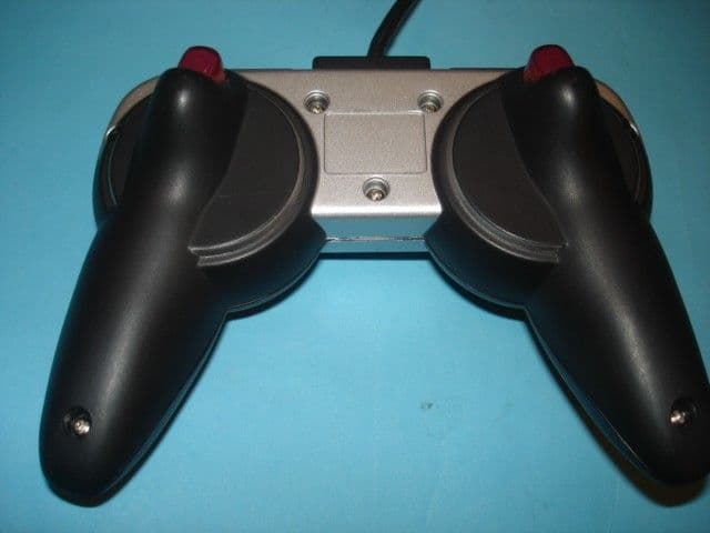
Click to zoom
Application Details
- Equipment Class
- DXX - Part 15 Low Power Communication Device Transmitter
- Date of Grant
- Aug 01, 2006
- Application Purpose
- Original Equipment
- Date of Application
- Aug 01, 2006
- Equipment Note
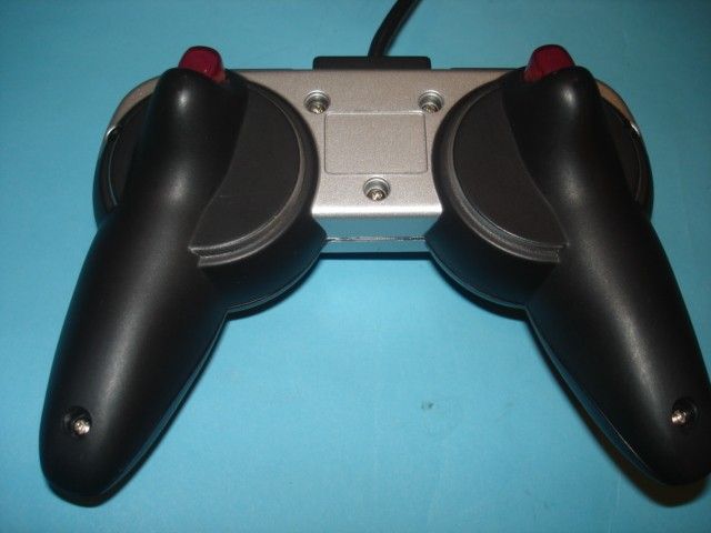
- HYPER SCAN
- Frequency Range
- 13.56000000 - 13.56000000
- Country
- Hong Kong
Documents & Files
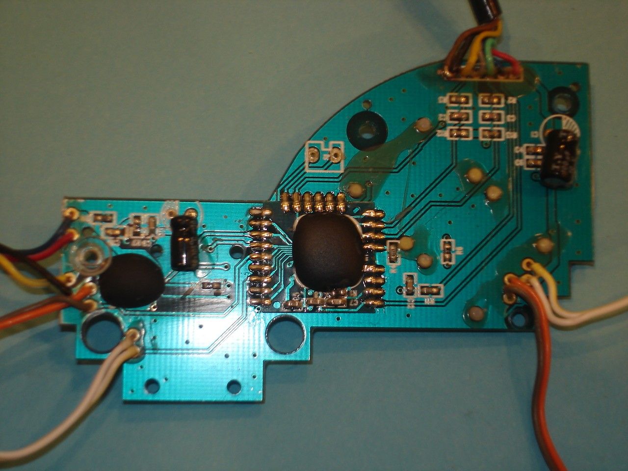
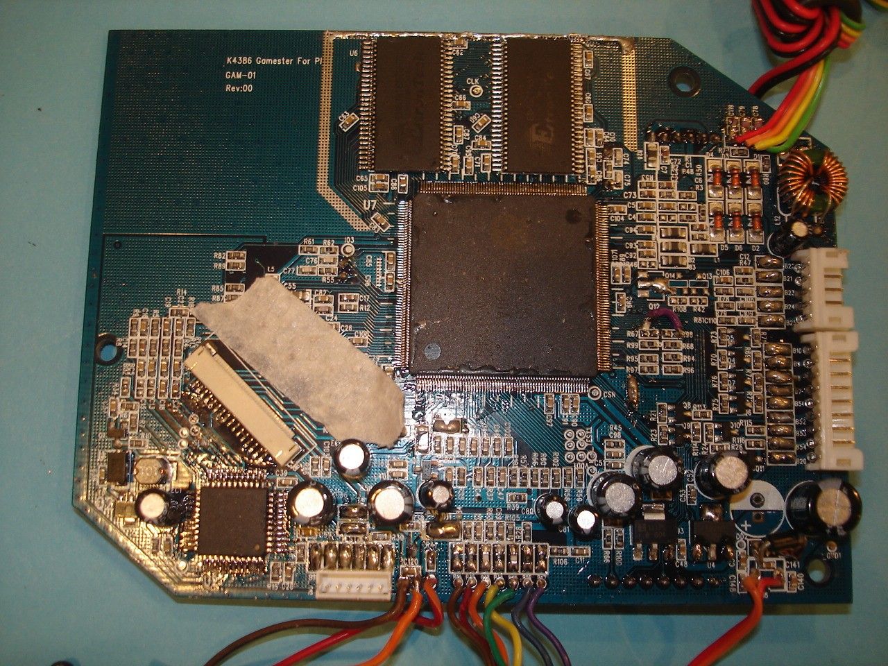
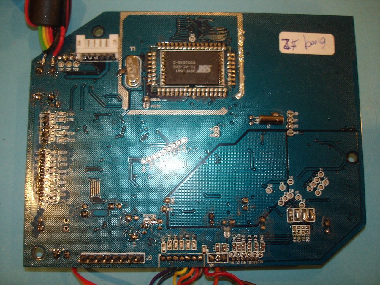
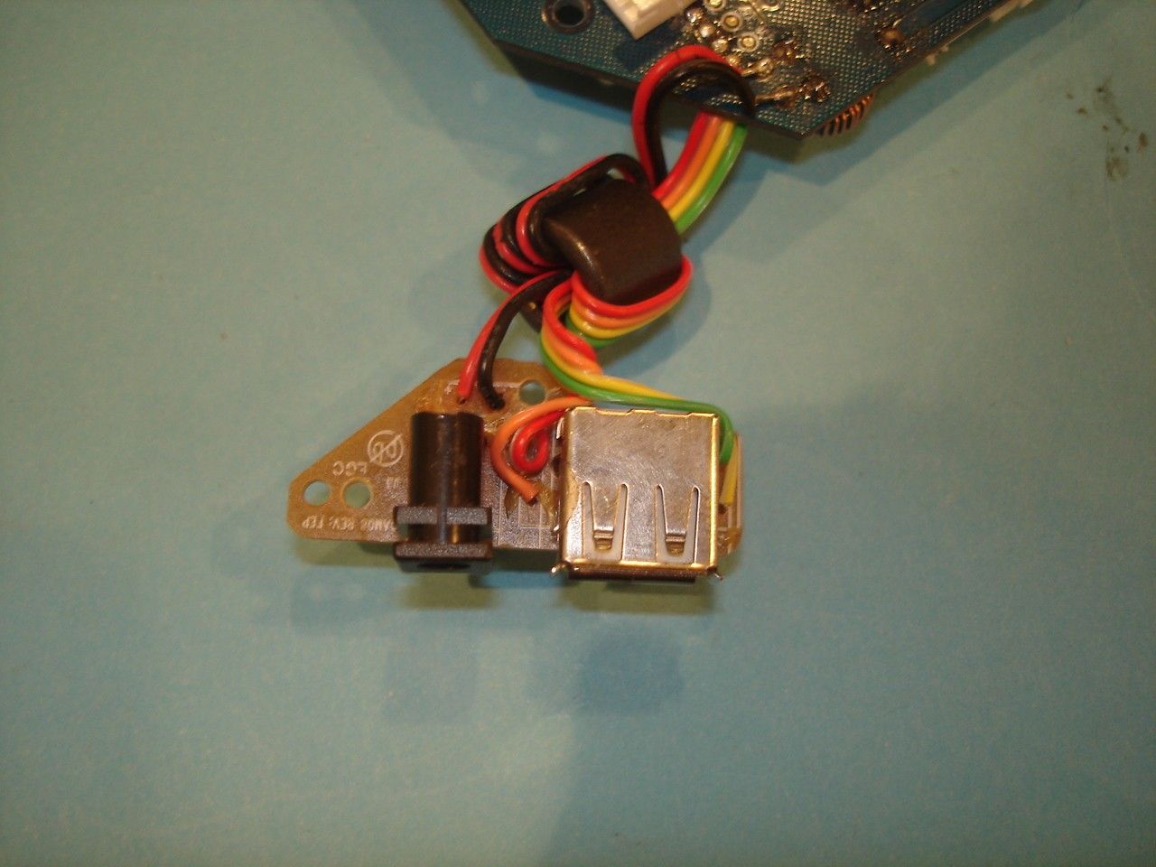
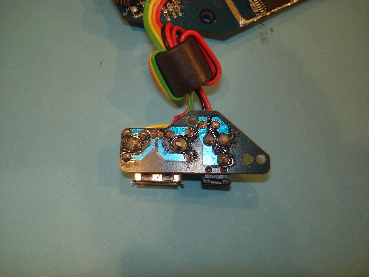
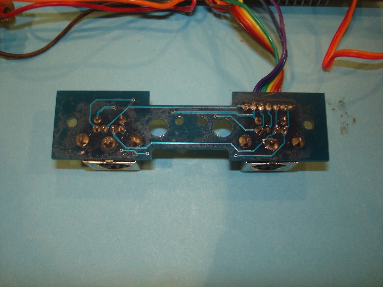
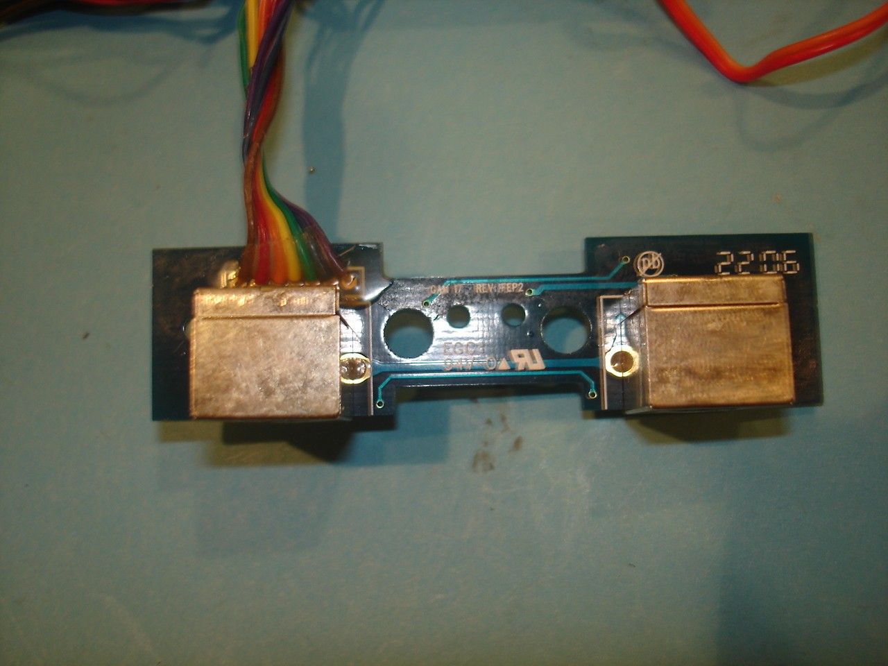
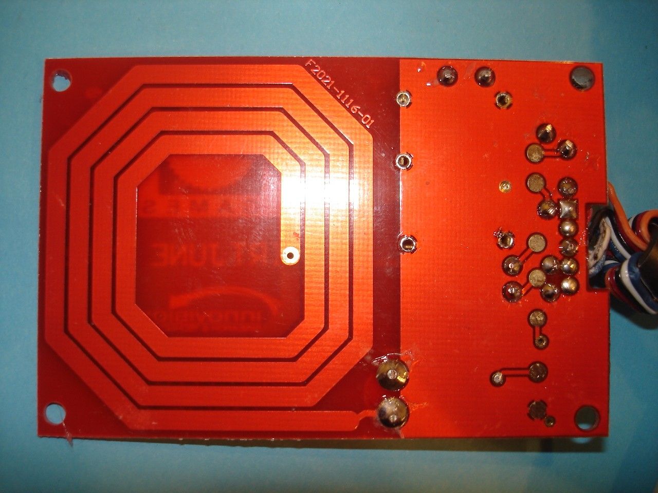
Document Text
Text extracted from the exhibit documents filed with the FCC. Open a document above to read the original.
Users Manual
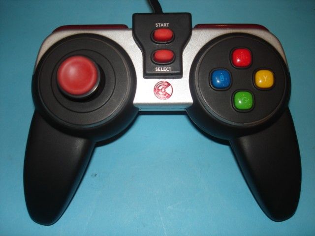
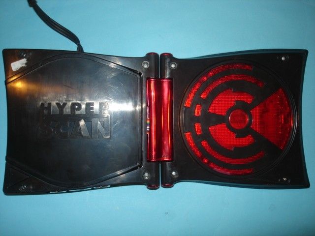
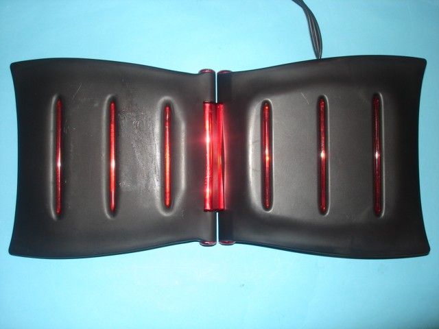
SCAN BATTLE RESCAN C O N S O L E I N S T R U C T I O N S K4386-0920 © 2006 Mattel, Inc. 333 Continental Blvd., El Segundo, CA 90245 U.S.A. All Rights Reserved. Printed in China TM CONSUMER INFORMATION Need Assistance? In the US and Canada, service.mattel.com or 1-800-524-8697, M-F 8AM – 6PM, ET. SCAN BATTLE RESCAN Keep these instructions for future reference as they contain important information. Contents: 1 HyperScan ™ game console 1 HyperScan ™ controller 1 A/C adapter (120v in/6v out) 3 RCA cables 1 X-Men game disc 6 X-Men game cards 1 Instruction Manual Please remove all components and compare them to the content list. If any items are missing, please call 1-800- 524-8697. Outside the U.S., please consult your telephone directory for a listing of your local Mattel office. SCAN BATTLE RESCAN Table Of Contents Setting Up Your System Controller Configuration Using Intellicard ™ Collectible Game Cards Dos And Don’ts Trouble Shooting SCAN BATTLE RESCAN Setting Up Your System 1 Set console on a flat, stable surface. 2 Open console and rest both sides on the flat surface. 3 With both your Hyper Scan ™ console and your TV/VCR/ DVD player(s) in the off position, locate the AV cable attached to your Hyper Scan ™ console; there should be one yellow, one red and one white connector. These cables need to be plugged into your TV or VCR/DVD player. Plug the yellow connector into the yellow “Video In” jack on your TV or VCR/ DVD player. Plug the white connector into the white “Audio In” (L) jack on your TV or VCR/DVD player and plug the red connector into the red “Audio In” (R) jack. The video and audio inputs are usually in the front or the back of your TV, VCR or DVD. However, depending on the type of TV or VCR/DVD you have, they could be in different places. If you are plugging your game console into your VCR or DVD player, your VCR or DVD player needs to be connected to the TV and then turned ON or your HyperScan ™ console will not work. If you are connecting your game console directly to your TV and there is a cable box connected to your television, you will need to access the set up menu on SCAN BATTLE RESCAN your TV and change the source of the input just as if you were using a VCR or DVD player. You will probably need to use your television’s original remote to access the menu. If you do not have the original remote, refer to your TV’s owner’s manual for instructions on how to do this without the remote control. If you have an older TV set that does not have audio or video inputs you will need to purchase an “RF Modulator”. These can be purchased from most elec- tronic stores. If your TV /VCR/ DVD player is mono, and not stereo, you will need to use a Y adaptor (not included) to connect the jacks to your television set. 4 Plug Controller(s) into the HyperScan ™ console, as shown. Align arrow on plug with notch atop the Din socket on console, as shown. Main controller should be plugged into the left socket, additional controller into the right socket. 5 Plug the DC jack of the AC adaptor into your HyperScan ™ console. 6 Plug AC plug of the AC adaptor into a 120 volt AC outlet. 7 Turn ON your television. 8 Turn on your HyperScan ™ console. The LED should illuminate momentarily. SCAN BATTLE RESCAN 4 53 Not for all TV sets. Red Yellow White Game Disc PlayerCard Scanner PowerDisc ReleaseController Plugs SCAN BATTLE RESCAN Right Shoulder – ActionLeft Shoulder – Action Right Trigger – ActionLeft Trigger – Action IMPORTANT! Only HyperScan ™ controllers are supported by this console, the use of other joysticks, paddles or peripherals may cause damage to your system and/or will cause it to not function properly. 11 Follow instructions on your TV screen. 12 Use your controller to navigate the menus. (see page tbd) Using Hyperscan ™ Controller Note: These instructions indicate general, non-specific functions. Precise actions will be described in detail in the instruction manual of your game pack. SCAN BATTLE RESCAN StartSelect Forward Left Back Right Red – Action Blue – Action Yellow – Action Green – Action 9 Locate the Input/Video button on your TV or the remote control. Press the Input/Video button until your reach a screen that displays the HyperScan ™ logo. 10 Open the CD compartment and place the game disc, printed side up, into the compartment on the center hub. DO NOT TOUCH THE LENS! You may then close the compartment cover. Don’t drop, hit or otherwise abuse your console or its components Don’t disassemble or try to repair this device. If problems occur, press the Power button OFF and unplug the AC adapter from the wall power source. Restart your Hyper Scan™ console by plugging in the AC adaptor and turn- ing it ON. If problems persist, consult the warranty information located at the end of these instructions. Don’t rapidly and repeatedly turn the power ON and OFF. This product contains a magnet. Do not use around items that are sensitive to or affected by magnetic fields. NOTE: Changes or modifications not expressively approved by the manufac- turer responsible for compliance could void the user’s authority to operate the equipment. SCAN BATTLE RESCAN Using Intellicard ™ Collectible Game Cards Hold your game card by the lower right corner, with the character illustra- tion facing down. Slowly scan the upper section of your card within one half inch above the center of the glow- ing red panel on your game console. After being prompted, you will have five seconds to scan your card. You will hear a sound confirming that the encrypted information has been deci- phered/accepted and your character will appear onscreen momentarily. During gameplay you may scan your modification (MOD) cards to enhance and customize your character’s fighting skills. Caring For Intellicard ™ Game Cards Although the patented technology embedded in our IntelliCard ™ Game Cards is quite durable, please do not mishandle or mistreat your cards, as abuse will adversely affect their performance. DOs and DON’Ts Dos Disconnect fr…
Text truncated - open the document above for the full version.
Block Diagram
Block Diagram of Hyper Scan (K4386) Prepared by: Ivan Chang Date: 6/25/2006 A. Block diagram Sunplus SPG290A (32-bit uP) (OSC = 27MHz) Boot ROM 1MB SDRAM 4M x 16 (2pcs) Clock speed = 108MHz Audio/Video (to TV) Motor driver CMD5901 CD Mechanism Sony KSM900ASI (2X speed) USB (host and device) RFID reader (OSC =13.56MHz) 8 LEDS (for decoration) GPIO Joystick controller port x 2 MCU Sunplus SPC11024 (6MHz) ADC Winbond W55AD808 VR for X/Y dir. 10 buttons Joystick controller system
Operational Description
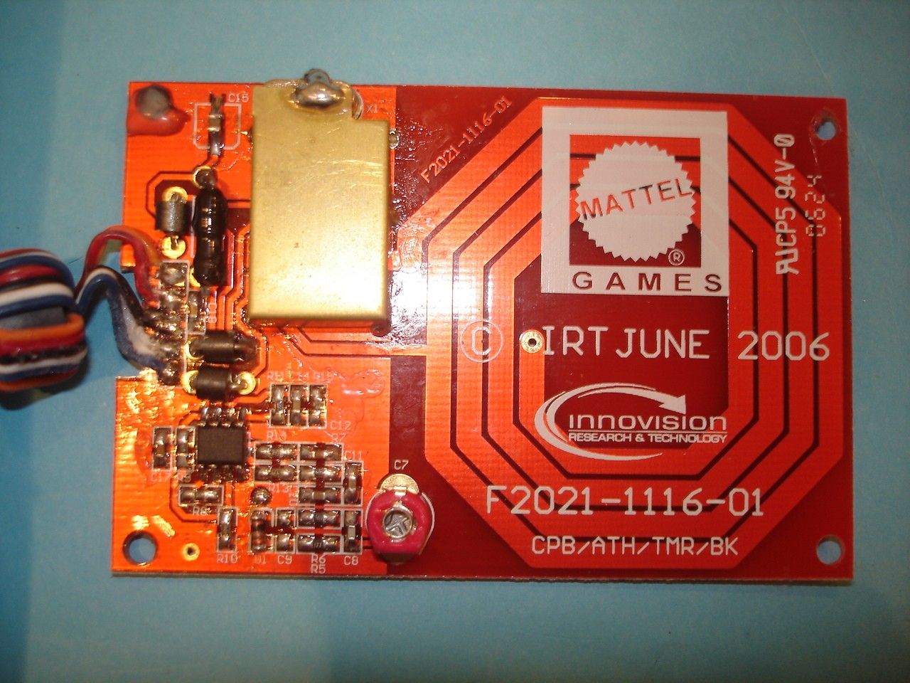
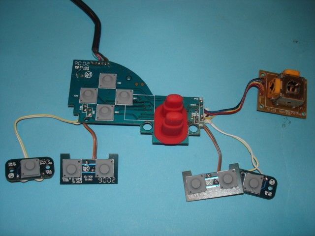
Operation Description 1. SPG290A is a highly integrated solution for variant multimedia applications including Portable Media Players, TV game consoles, Educational Learning Aids and also handheld game pad. Its rich set of features comes with affordable cost and superior support from Sunplus to make system companies realize their great ideas for personal entertainment platform. - Sunplus S+Coreô32 bits RISC - Advanced memory control interface for SDRAM/NAND Flash/NOR Flash/MASK ROM - CMOS sensor interface with motion detection and image recognition - USB Host/Device - SD Card Interface - Hi performance 2D graphic engine (Picture Processor Unit) with VGA resolution - Frame buffer control with BITBLT DMA - LCD controller supporting CSTN and TFT panels - Built-in TV encoder for Composite VIDEO output - 24 PCM/ADPCM channels for MIDI synthesizer - Built-in stereo audio DAC - 12 bits ADC - Built-in CD servo controller for CD-based applications - MPEG4 codec - MP3 decoder It is running at 108MHz in Hyper Scan. 2. Boot ROM: Holding the system boot code, firmware codes and test modes. 3. SDRAM: System RAM . It contains 2pcs of 4M x 16 to make 4M x 32 (16MB). They are running at 108MHz in the system. 4. Motor driver and CD mechanism: This is the CD-ROM module of the system. With the CD-servo control circuit inside SPG290A. It is able to read CD-ROM (proprietary format) and Audio CD. Its maximum speed is 2X. 5. RFID reader: It is a 13.56MHz RFID reader to read and write the RFID tag. The tag has 128 bytes memory and accessed by the GPIO via the RFID reader. 6. LEDs: 8pcs for decoration and indications. 7. Joystick controller: It is using Sunplus SPC11024A (running at 6MHz). It connects to an ADC to capture analog inputs from the VRs. END
Schematics
55 44 33 22 11 D D C C B B A A VIDEO_O GND AUDIO_L_OUTAUDIO_R_OUTVIDEO_O AUDIO_L_OUT AUDIO_R_OUT AV33_VDAC AV33_VDAC AV33_VDAC AV33_VDAC AV33_ADAC AV33_ADACAUDIO_VREF VIDEO_OUT VIDEO_CBL VIDEO_VREF VIDEO_CBU VIDEO_RSET AUDIO_R AUDIO_L TitleSize Document Number Rev Date: Sheet of SPG290 main board 6tH TV OUT B 1 7 Tuesday, July 25, 2006 Mattel Inc Design by Daniel Stelung TitleSize Document Number Rev Date: Sheet of SPG290 main board 6tH TV OUT B 1 7 Tuesday, July 25, 2006 Mattel Inc Design by Daniel Stelung TitleSize Document Number Rev Date: Sheet of SPG290 main board 6tH TV OUT B 1 7 Tuesday, July 25, 2006 Mattel Inc Design by Daniel Stelung Please place this circuit close to the SPG290 chip. Please place this circuit close to the VIDEO out connector. TV OUT AUDIO OUT D31N4148D31N4148 D21N4148D21N4148 C1 NC C1 NC B28BEADB28BEAD B1BEADB1BEAD B3BEADB3BEAD D41N4148D41N4148 B2BEADB2BEAD C3 0.1U C3 0.1U D61N4148D61N4148 C6 470P C6 470P C4 0.1U C4 0.1U C2 NC C2 NC L1BEADL1BEAD C7 470P C7 470P R3 75 R3 75 C847UC847U D51N4148D51N4148 D1 1N4148 D1 1N4148 C50.1UC50.1U R2 1.2K R2 1.2K R1 3.3K R1 3.3K 123456 J1CON6J1CON6 55 44 33 22 11 D D C C B B A A DRAM_BA0DRAM_BA1DRAM_DQM0DRAM_DQM1DRAM_DQM2DRAM_DQM3 DRAM_CAS ROMCSN DRAM_A[0..12]DRAM_D[0..31] DRAM_A5DRAM_DQM2DRAM_DQM0DRAM_A4DRAM_A6DRAM_A0DRAM_A12DRAM_DQM1DRAM_A3DRAM_A1DRAM_A8DRAM_A9DRAM_A2DRAM_BA1DRAM_A10DRAM_A11DRAM_BA0DRAM_A7 DRAM_D3DRAM_D0DRAM_D7DRAM_D19DRAM_D17DRAM_D5DRAM_D16DRAM_D4DRAM_D6DRAM_D2DRAM_D23DRAM_D21DRAM_D20DRAM_D1DRAM_D18DRAM_D22 DRAM_DQM3DRAM_D8DRAM_D9DRAM_D10 DRAM_WE DRAM_WEDRAM_WEDRAM_WEDRAM_WEDRAM_CASDRAM_CASDRAM_CASDRAM_CASDRAM_CASDRAM_CASDRAM_CASDRAM_CASDRAM_CASDRAM_CASDRAM_CASDRAM_CAS ROMCSNROMCSNROMCSNROMCSN VDD33_1VDD33_1VDD33_1VDD33_1VDD33_1VDD33_1VDD33_1VDD33_1VDD33_1VDD33_1VDD33_1VDD33_1VDD33_1VDD33_1VDD33_1VDD33_1VDD33_1VDD33_1VDD33_1VDD33_1VDD33_1VDD33_1VDD33_1VDD33_1VDD33_1VDD33_1VDD33_1VDD33_1VDD33_1VDD33_1VDD33_1VDD33_1VDD33_1VDD33_1VDD33_1 DRAM_A[0..12]DRAM_D[0..31] VDD33_1 VDD33 VDD33 VDD33 VDD33 DRAM_BA0DRAM_BA1 DRAM_DQM0DRAM_DQM1DRAM_DQM2DRAM_DQM3 DRAM_CAS ROMCSNDRAM_WE TitleSize Document Number Rev Date: Sheet of SPG290 main board 6th Boot ROM 1Mx16 A 2 7 Tuesday, July 25, 2006 Mattel Inc Design by Daniel Stelung TitleSize Document Number Rev Date: Sheet of SPG290 main board 6th Boot ROM 1Mx16 A 2 7 Tuesday, July 25, 2006 Mattel Inc Design by Daniel Stelung TitleSize Document Number Rev Date: Sheet of SPG290 main board 6th Boot ROM 1Mx16 A 2 7 Tuesday, July 25, 2006 Mattel Inc Design by Daniel Stelung The Part use the flash/maskrom compatible layerAnd,this part have change to 64M bit Make sure the "small flash PCB" layer is the same6tH PCB ONLY5tH PCB the DRAM_WE ADD B4VDD33 ADD B27ROMCSN ADD B5DRAM_CAS ADD B6 A0 25 A1 24 A2 23 A3 22 A4 21 A5 20 A6 19 A7 18 A8 8 A9 7 A10 6 A11 5 A12 4 A13 3 A14 2 A15 1 A16 48 A17 17 D0 29 D1 31 D2 33 D3 35 D4 38 D5 40 D6 42 D7 44 D8 30 D9 32 D10 34 D11 36 D12 39 D13 41 D14 43 D15 45 WE 11 CE 26 OE 28 A18 16 NC 15 NC 47 VDD 37 VSS 46 VSS 27 A19 9 A20 10 A21 13 RST 12 WP 14 U1 SST39VF6401/6402 U1 SST39VF6401/6402 C11 0.1U C11 0.1U C9 0.1U C9 0.1U C12 0.1U C12 0.1U C10 0.1U C10 0.1U 55 44 33 22 11 D D C C B B A A MUTE2MOTMUTECDS_VREF1 SL+ GND_MO F+ T+ F- SPIN CDS_FCOP CDS_VREF1 CDS_CDMDI CDS_SLCO CDS_VREF1 MUTE2 CDS_VREF1 CDS_VREF1 CDS_TCOPCDS_VREF1 MOTMUTE FIN GND_MO CDS_VREF1 CDS_TEST1CDS_TRAYN MOTOFFMOTMUTE GND_MO SL- SP- T- MOTOFF PUH_LD GND_MO GND_MO GND_MO SP+ TIN GND_MO CDS_SPCO CDS_VREF1 CDS_VREF1CDS_VREF1CDS_VREF1 SLIN CDS_CDMDICDS_CDMDICDS_CDMDICDS_CDMDICDS_CDMDICDS_CDMDI PUH_LD E PD1 FPD2 CDS_CDFCDS_CDBCDS_CDACDS_CDE F+T+T-F- SP+SP-SL+SL- CDS_LIMSW CDS_VREF1 AVDD33_CDS AVDD33_MO AVDD33_MO AVDD33_MO AVDD33_MO AVDD33_MO AVDD33_MO AVDD33_CDS AVDD33_MO AVDD33_CDS CDS_OPCLSCDS_FCOPCDS_OPOCDS_OPI CDS_VREFOCDS_PDFLTCDS_LPFNINCDS_LGINCDS_SLVLVDS_CNINCDS_RFOCDS_RFRPLPCDS_RFDCOCDS_RFSUM CDS_CDECDS_CDACDS_CDBCDS_CDFCDS_CDMDI CDS_CDLDO CDS_VREF1 CDS_SVOTSTCDS_SBADPHCDS_SBADCDS_FEOCDS_TEOCDS_TEXOLP CDS_TEST1CDS_LIMSWCDS_TRAYNCDS_SPCOCDS_SLCOCDS_TCOP CDS_SC2CDS_RFISCDS_SC1CDS_RFDCICDS_RFRP GND_MO CDS_TEST2 TitleSize Document Number Rev Date: Sheet of <Doc> 6th <Title> C 3 7 Tuesday, July 25, 2006 TitleSize Document Number Rev Date: Sheet of <Doc> 6th <Title> C 3 7 Tuesday, July 25, 2006 TitleSize Document Number Rev Date: Sheet of <Doc> 6th <Title> C 3 7 Tuesday, July 25, 2006 To SONY KSM900AAA COMPONENTS FOR EMC COMPONENTS FOR EMC 123456 CN2 Motor KSM900AAA CN2 Motor KSM900AAA R32 5.1KR32 5.1K C149100PC149100P C19 500PC19 500P B18 B18 BC50.1UBC50.1U C42 1UC42 1U _TEST4_TEST4 BSEN 1 BATT 2 RESET 3 DEAD 4 SW 5 EO 6 EI 7 SPRT 8 CT 9 NC 10 OP- 11 IN1 22 MUTE2 21 IN2 20 MUTE34 19 IN4 18 IN3 17 VREF 16 VSYS2 15 OP+ 14 OPOUT 13 VSYS1 12 RCHG 33 OUT1- 32 OUT1+ 31 OUT2- 30 OUT2+ 29 POWGND 28 OUT3+ 27 OUT3- 26 OUT4+ 25 OUT4- 24 BRAKE 23 AMUTE 34 EMP 35 HVCC 36 PWM 37 CLKIN 38 START 39 OFF 40 CHGVCC 41 EMPSET 42 PREGND 43 PWMFIL 44 U2 BA5901 U2 BA5901 C144100PC144100P R3010KR3010K EE 1 3 2 Q2ROHM 2SA1797Q2ROHM 2SA1797 2 13 Q12N3906Q12N3906 BC30.1UBC30.1U R37 100K R37 100K _TCOP1_TCOP1 B41 B41 C22 500P C22 500P R31 51KR31 51K R18 12K R18 12K C17 0.01U C17 0.01U C150100PC150100P C31 68PC31 68P R86 82 R86 82 _SLIN1_SLIN1 B45 B45 C21500PC21500P C34 10UC34 10U + C3647U + C3647U BB C32 NCC32 NC R20 1.5KR20 1.5K C46 470PC46 470P C151100PC151100P _SPCO1_SPCO1 R33 0R33 0 C15NCC15NC R3510R3510 R91 39K R91 39K AA 1 2 L310UHL310UH R17 10K R17 10K BC41UBC41U C18500PC18500P C145100PC145100P C28 2200P C28 2200P C152100PC152100P R88 39K R88 39K R19 5.1KR19 5.1K C14 0.01U C14 0.01U B40 B40 B50B50 C44 820PC44 820P C30 200PC30 200P R9 3K R9 3K _SLCO1_SLCO1 R27 0R27 0 R25 2KR25 2K C29 NCC29 NC D71N5819D71N5819 _TEST3_TEST3 C20 1000PC20 1000P L2 COIL 100U L2 COIL 100U C16 0.1U C16 0.1U C411UC411U B55 B55 _TIN1_TIN1 C38 0.1U C38 0.1U R5 10K R5 10K R7 10K R7 10K B58 B58 R8 3K R8 3K R16 20K R16 20K C23 1U C23 1U R2275KR2275K C25 0.22UC25 0.22U C43 0.047UC43 0.047U _TEST2_TEST2 B39 B39 2 13 Q3 2N3906 Q3 2N3906 R9…
Text truncated - open the document above for the full version.
Schematics
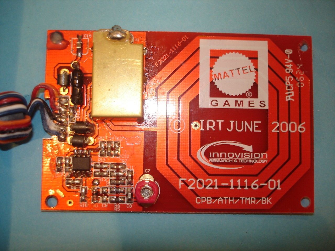
1 2 3 4 5 6 78 ABCD 8 7 6 5 4 3 2 1 D CBA MAITAI SMT READER SCHEMATIC F2021-1115 Sheet: 1 of 1 PROJECT: TITLE:DRG No: © INNOVISION R&T plc. www.innovision-group.com INNOVISION RESEARCH & TECHNOLOGY plc WOKINGHAM, BERKS, RG40 1XS F +44 (0) 118 979 1500T +44 (0) 118 979 2000 ASH COURT, 23 ROSE STREET, THIS DRAWING IS SUPPLIED UNDER THE TERMS OF THE CONFIDENTIALITY AGREEMENT SIGNEDBETWEEN INNOVISION AND YOU. THE DESIGNAPPEARING HEREON MUST NOT BE DISCLOSEDWHOLLY OR PARTIALLY TO THIRD PARTIES OR FEATURES OF THE DESIGN INCORPORATED INTO PROJECTS WITHOUT THE WRITTEN CONSENT OF INNOVISION. ISS ECR No REV SIGNED DATE MAITAI Drawn:Eng:PM: A T HILLSA T HILLS Date:Date:Date: COMMENTS: 9-Jun-2006 15:48:14 F2021-1115-01.Sch Printed: 09-JUN-06 File: A3 Size 125/5/0105 - A3 External Connections ENABLE GATEDATA VSGND 12345 J1SIL_5 (Pads on PCB) 01 - CREATED ATH 09-JUN-06 Wire Colours WhiteRedBlueOrangeBlack CLIENT CONNECTOR DESIGNATION DO NOT CHANGE ! LOGO C P BROOKS X113.56MHz C7 4-20pF ENABLE GATE DATA L2 TP1TESTPOINT C333pF C233pF C12 10nF C410nF C6180pF C1047pF R61M D1 LL4148 R7100K C1147pF R51K2 C833pF L11uH R31M R21M C9DNF R9470K R10470K R11 100K C143n3F R13470K R42K2 TP2 TESTPOINT TP4TESTPOINT TP3TESTPOINT TP6TESTPOINT TP5TESTPOINT 9 10 8 IC1C74HC00 R11M C1100pF GND GND + C1510uF C16100nF C17100nF VCC GND 3 12 147 IC1A74HC00 6 45 IC1B74HC00 1213 11 IC1D74HC00 VCC L310uH VS VCC FB1 SPM0425 FB2 SPM0425 FB3 SPM0425 56 7 IC2BLM358M(8) 48 23 1 IC2ALM358M(8) 47KR14 R81M C18100nF 09-JUN-06 R1210 TP7TESTPOINT 09-JUN-06
Test Report
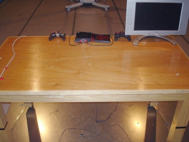
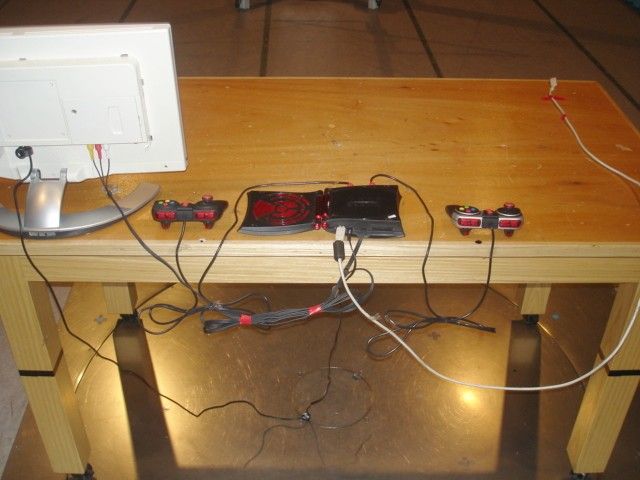
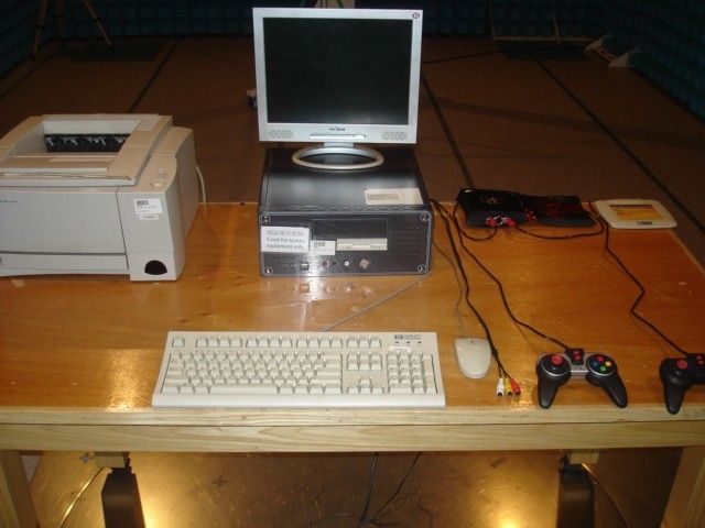
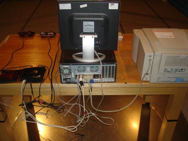
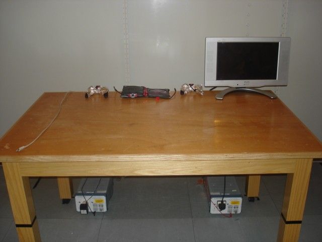
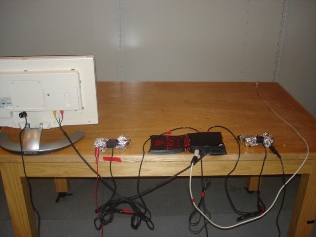
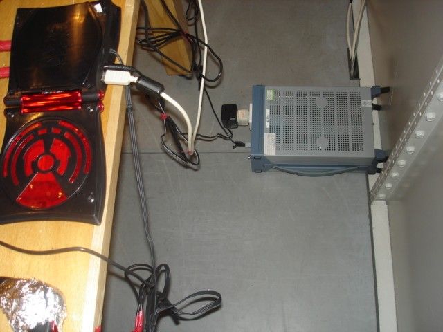
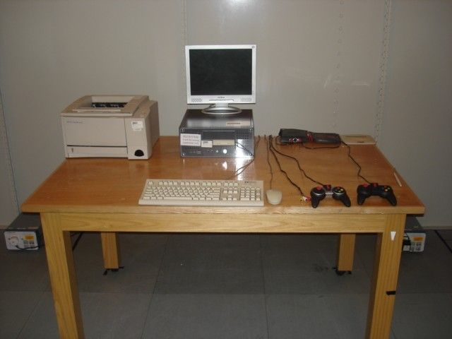
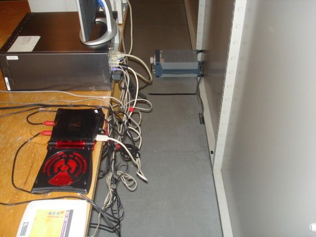
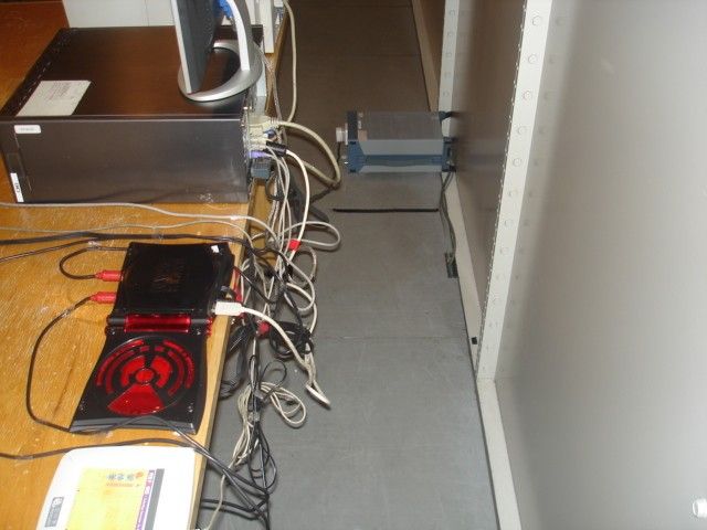
TEST REPORT Report No. : AG018255-001 Date : 2006 July 29 Page 1 of 14 FCC ID: PIYK4386-06A1T This document shall not be reproduced except in full or with written approval by the laboratory. CMA Industrial Development Foundation Limited Room 1302, Yan Hing Centre, 9-13 Wong Chuk Yeung St.., Fo Tan, Shatin, Hong Kong. Tel: (852) 2698 8198 Fax: (852) 2695 4177 E-mail: [email protected] Web Site: http://www.cmatcl.com Application No. : LG214761(0) Client : Mattel Asia Pacific Sourcing Limited 13/F., South Tower, World Finance Centre, Harbour City, Tsim Sha Tsui, Kowloon, Hong Kong Sample Description : One(1) submitted sample(s) stated to be Hyper Scan of Model No. K4386 Rating : AC 120V to DC 6V adaptor No. of submitted sample : Two(2) set(s) *** Date Received : 2006 July 3 Test Period : 2006 July 3 – 2006 July 24 Test Requested : FCC Part 15 Certification. Test Method : 47 CFR Part 15 (10-1-05 Edition) ANSI C63.4 – 2003 Test Result : See attached sheet(s) from page 2 to 14. Conclusion : The submitted sample was found to comply with requirement of FCC Part 15 Subpart B and C. For and on behalf of CMA Industrial Development Foundation Limited Authorized Signature : ____________________________________________________ Danny Chui Deputy Manager - EL. Division TEST REPORT Report No. : AG018255-001 Date : 2006 July 29 Page 2 of 14 FCC ID: PIYK4386-06A1T This document shall not be reproduced except in full or with written approval by the laboratory. CMA Industrial Development Foundation Limited Room 1302, Yan Hing Centre, 9-13 Wong Chuk Yeung St.., Fo Tan, Shatin, Hong Kong. Tel: (852) 2698 8198 Fax: (852) 2695 4177 E-mail: [email protected] Web Site: http://www.cmatcl.com Table of Contents 1 General Information............................................................................................................................. 3 1.1 General Description ..................................................................................................................... 3 1.2 Location of the test site ................................................................................................................ 4 1.3 List of measuring equipment........................................................................................................ 5 1.4 List of support equipment ............................................................................................................ 6 2 Description of the radiated emission test ............................................................................................. 7 2.1 Test Procedure ............................................................................................................................. 7 2.2 Test Result ................................................................................................................................... 7 2.3 Radiated Emission Measurement Data ........................................................................................ 8 3 Description of the Line-conducted Test............................................................................................. 11 3.1 Test Procedure ........................................................................................................................... 11 3.2 Test Result ................................................................................................................................. 11 3.3 Graph and Table of Conducted Emission Measurement Data ................................................... 11 4 Photograph ......................................................................................................................................... 12 4.1 Photographs of the Test Setup for Radiated Emission and Conduction Emission..................... 12 4.2 Photographs of the External and Internal Configurations of the EUT....................................... 12 5 Supplementary document................................................................................................................... 13 5.1 Bandwidth .................................................................................................................................. 13 5.2 Duty cycle .................................................................................................................................. 13 5.3 Transmission time ...................................................................................................................... 13 5.4 Frequency Error .......................................................................................................................... 13 6 Appendices......................................................................................................................................... 14 TEST REPORT Report No. : AG018255-001 Date : 2006 July 29 Page 3 of 14 FCC ID: PIYK4386-06A1T This document shall not be reproduced except in full or with written approval by the laboratory. CMA Industrial Development Foundation Limited Room 1302, Yan Hing Centre, 9-13 Wong Chuk Yeung St.., Fo Tan, Shatin, Hong Kong. Tel: (852) 2698 8198 Fax: (852) 2695 4177 E-mail: [email protected] Web Site: http://www.cmatcl.com 1 General Information 1.1 General Description The equipment under test (EUT) is a multi function product for Hyper Scan. It is operated at 27MHz for MCU oscillation and it has 2unit of 4MB x 16 SDRAM for data storage. For the game controller, the operation clock is 6MHz and it has 10pcs of button keys + single joystick for user play the game. The maximum connection for game controller is 2pcs at the same time. During the TV game mode, the player can put the game card on the RFID detector to change the game details. The radio frequency for RFID is 13.560MHz and generated by the crystal. The Hyper Scan has a loop antenna for coupling the game card data. For the USB connection, it can plug in the PC and transfer the data to Hyper Scan. - SPG290A, 27MHz crystal and associated circuit a…
Text truncated - open the document above for the full version.
Test Report
Job No.: _______________ WF-EL-EMC-15 Edition 1 2006 April 12 Page of Bandwidth Plot Bandwidth 1 Bandwidth 2
Contact Information
Applicant
Joule Mak(Director, Electronic Engineering)
Test Firm
CMA Industrial Development Foundations LimitedStephen Lam
Technical Specifications
| # | Rule Parts | Frequency Range | Power Output |
|---|---|---|---|
| 1 | 15C | 13.56 MHz - 13.56 MHz | - |
Other Applications from Mattel Asia Pacific Sourcing Ltd.
PIY-HTX00-24-A5T
Jan 17, 2024Fisher-Price Link Squad Jam & Count Panda
Equipment Class
DXX - Part 15 Low Power Communication Device TransmitterPIY-HTX03-24-A5T
Jan 17, 2024Fisher-Price Link Squad A to Z Yak
Equipment Class
DXX - Part 15 Low Power Communication Device TransmitterPIY-HTX04-24-A5T
Jan 17, 2024Fisher-Price Link SquadBop & Groove Tiger
Equipment Class
DXX - Part 15 Low Power Communication Device TransmitterPIY-HTW99-24-A5T
Jan 17, 2024Fisher-Price Link Squad Opposites Fox
Equipment Class
DXX - Part 15 Low Power Communication Device TransmitterPIY-HTX01-24-A5T
Jan 17, 2024Fisher-Price Link Squad Crawl n Colors Chameleon
Equipment Class
DXX - Part 15 Low Power Communication Device Transmitter