PIYK7238-07A4TDUNE DEVIL PRO
Mattel Asia Pacific Sourcing Ltd.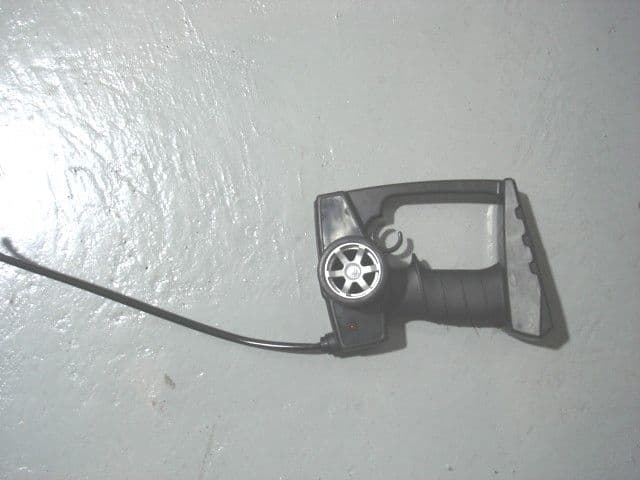
Click to zoom
Application Details
- Equipment Class
- DXX - Part 15 Low Power Communication Device Transmitter
- Date of Grant
- Oct 05, 2006
- Application Purpose
- Original Equipment
- Date of Application
- Oct 05, 2006
- Equipment Note
- DUNE DEVIL PRO
- Frequency Range
- 49.86000000 - 49.86000000
- Country
- Hong Kong
Documents & Files
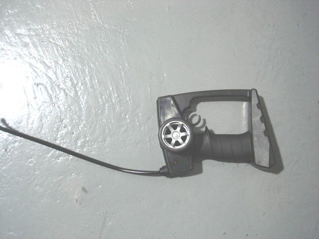
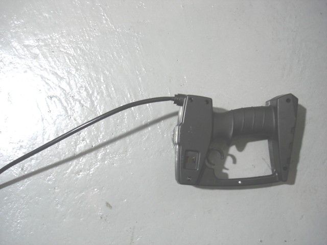
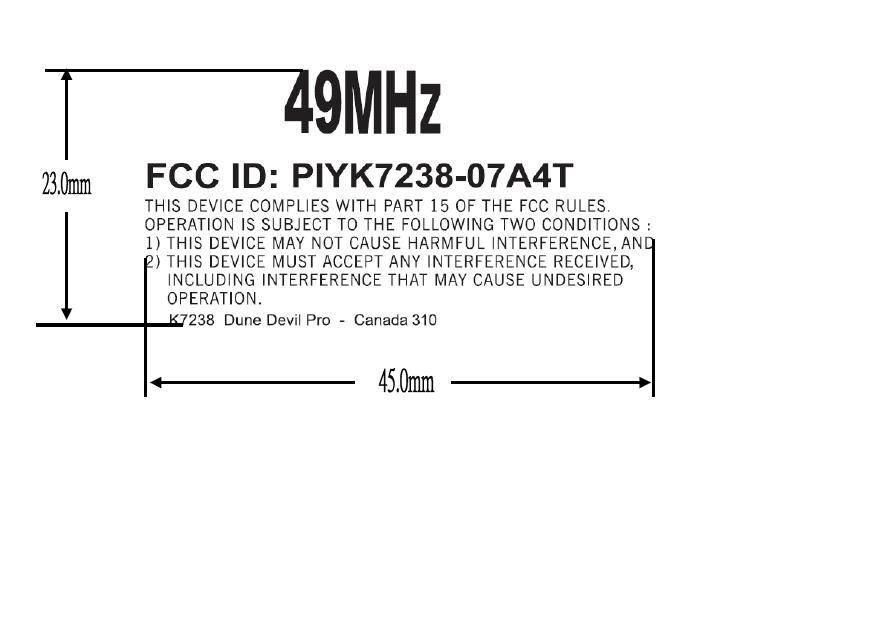
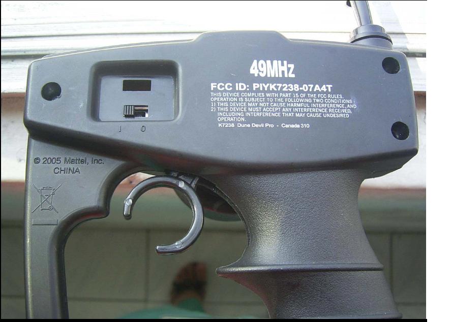
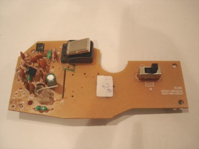
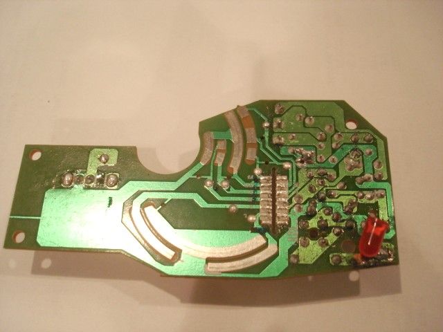
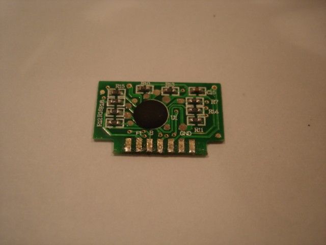
Document Text
Text extracted from the exhibit documents filed with the FCC. Open a document above to read the original.
Users Manual
XCAUTION:Surfaces may become hot an d cause burn s if electron ics g et w et. D o n ot op erate v ehicle throug h w ater or sn ow . K e e p th e s e in s tr u c tio n s fo r fu tu r e r e fe r e n c e a s th e y c o n ta in im p o r ta n t in fo r m a tio n . IM P OR TANT: P le a s e r e a d a ll ì Co n s u m e r In fo r m a tio n î b e fo r e o p e r a tin g y o u r v e h ic le . I. CONTE NTS / F E ATUR E S V ehicle T ran smitter V e h i c l e A n ten n a * Y ou w ill n eed to slip the loose an ten n a w ire in to the p rov id ed tube (it look s lik e a straw ). T hen p ush the straw (w ith w ire alread y en closed ) rmly in to the cylin d rical op en in g on the chassis. Steerin g ad juster * T urn w ith a screw d riv er (n ot in clud ed ) to k eep v ehicle run n in g straig ht. O N (I)/O F F (O ) sw itch B attery d oor !A A B attery ad ap ter Tr a n s m i t t e r LA n ten n a RL E D in d icator(L ig ht that in d icates w hen your tran smitter is turn ed on or off). @Steerin g k n ob: left / rig ht con trol MT rig g er: forw ard / rev erse con trol OO N (I)/O F F (O ) sw itch TB attery d oor * J ust turn your v ehicle O N . T hen p ull the trig g er an d you w ill be able to run an d con trol your v ehicle. * P ull trig g er all the w ay back for that ex tra p un ch of p ow er. A sst.K 9 5 8 1 K 7 2 3 7 /3 8 - 0 9 2 0 L R @ M Æ XCAUTION:T o p rev en t en tan g lemen t, k eep hair aw ay from w heels. I O IO O T I O I O ! Hot Wheels Æ R /C S U P P O R T Q u estion s or p rob lem s w ith y ou r p rod u c t? D O N íT R E T U R N IT T O T HE S T O R E ! J u st c a ll u s for help . U.S . c o n s u m e r s m a y a ls o r e g is te r th e ir p r o d u c ts a t th is n u m b e r . 1 -8 8 8 -5 5 7 -8 9 2 6 1 2 3 I O 1 2 3 I O II. VEHICLE OPERATION * If your vehicle doesnít move when you use the trans- mitter thereís a good chance your vehicleís battery is ready for a recharge. III. B ATTERY INSTALLATION Note: Your vehicle can be used with a TycoÆ R /C 9.6 V NiC d battery pack or 6 AA alkaline batteries. R eq uires a TycoÆ R /C 9.6 V NiC d battery pack or 6 AA alkaline batteries for vehicle and 2 AA alkaline batteries for transmitter. * Though your vehicle can run on both 9.6 V or 6 x AA batteries it will run up to 30% faster when using a 9.6 V rechargeable battery. Vehicle 9 .6 V NiCd battery pack 1. U se a screwdriver (not included) to unscrew the battery cover. 2. U nscrew and remove the AA battery adapter. Store in a safe place for later usage. 3. Insert the 9.6 V NiC d battery pack (not included), with polarity (+ /-) as shown inside the battery compartment . 4 . Plug the wire connector into the battery compartment as shown. 5. R eplace the battery cover. 6 AA alk aline batteries 1. U se a screwdriver (not included) to unscrew the battery cover. 2. M ake sure the AA battery adapter is rmly in place. If itís not, position the adapter in the box and fasten it with the screw. 3. Insert the 6 AA batteries (not included), with polarity (+ /-) as shown inside the battery compartment . 4 . R eplace the battery cover. Transmitter 1. R emove the battery cover as shown. 2. Install 2 AA batteries (not included), with polarity (+ /-) as shown inside the battery compartment. 3. R eplace the battery cover. * If the transmitterís LED indicator does not light when the transmitter is switched ON, itís time to replace the transmitter batteries. Simply install fresh batteries as described above. RIG HT FORW ARDREVERSELEFTRIG HT 9 .6 V d.c. NiCd, 1 x 8 îAAî, 7 0 0 mAh 6 x AA ; IV. QUICK TIPS 1. The best jumps are the ones where the rear wheels hit the ground first. Itís important to give your vehicle just enough power as it leaves the ramp. Too much power and your nose will rise abruptly, too little and youíll land on the front wheels. When you do land, make sure all four wheels are on the ground before you accelerate. If you donít you may cause a wheelie, which may look really cool, but youíll lose time. 2. The vehicle was meant to fly high and land soft but just because you can doesnít mean you should ñ especially if youíre in a race. Remember, the more time your vehicle spends in the air, the less time youíll have to accelerate. So stay low to win big! 3. Radio interference can affect your vehicleís perfor- mance. Interference can be caused by other R/C vehicles running on the same frequency, electrical wires, large buildings, CB radios or other wireless gear. Try to stay away from these! 4. Point your transmitter antenna up - not down toward your vehicle. If your vehicle gets too far away, it wonít work properly. 5. Donít drive your vehicle through water or snow. If your vehicle does get wet, wipe it with a towel and allow it to dry completely. 6. Donít store your vehicle near heat or in direct sunlight. Always turn switches OFF and remove all batteries for storage. XV. CONSUMER INFORMATION Note to adults: To ensure that the childís play is both safe and fun, please review all operating instructions and safety rules with your child. Safety Tips ï NEVER drive your vehicle on streets! Theyíre for real cars! ï DO NOT pick up vehicle while in motion. ï Take your fingers off the transmitter trigger and then pick it up. ï Keep fingers, hair and loose clothing away from the tires and the wheel hubs while the vehicle is switched ON. ï Adult supervision is recommended when this vehicle is being operated. ï To avoid accidental operation, remove all batteries when notin use. Always turn the vehicle OFF before removing batteries. BATTERY SAFETY INFORMATION In exceptional circumstances batteries may leak fluids that can cause a chemical burn injury or ruin your product. To avoid battery leakage: ï Non-rechargeable batteries are not to be recharged. ï Rechargeable batteries are to be removed from the product before being charged (if designed to be removable). ï Rechargeable batteries are only to be charged under adult supervision (if designed to be removable). ï Do not mix alkaline, stand…
Text truncated - open the document above for the full version.
Block Diagram
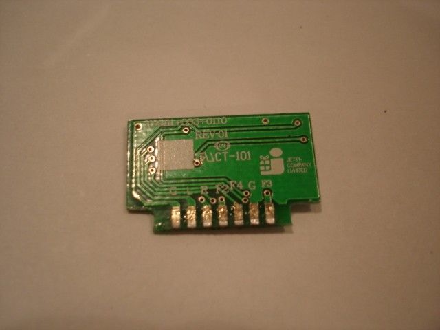
1 2 34 ABCD 4 3 2 1 D CBA 1 MATTEL 1 K723 8 00 9-Sep-2006 D:\Project\K9581\FCC\27M TX\K7237 27M TX BLOCK.sch MODEL NAME:Size: Model Number: Date: File: Revision: Sheet of Dune Devil DRAW BY: A4 ANTENNA CRYSTAL OSCILLATOR MODULATOR RF AMPLIFIER FILTER 49.860 MHz 3V AA BATTERY OFF 5MM RED LED SPRC201A RORC VDD VSS U1 LEFTRIGHT FORWARD1 FORWARD2 FORWARD3 FORWARD4 BLOCK-DIAGRAMK723 8 TRANSMITTER 49.860 MHz MAIN PCB : PIYK723 8 -07A 4 T DI0 DI1DI2DI3DI4 DI5 DOUT DI6 BACKWARD ON Cheung Y K
Operational Description
DUNE DEVIL #K7238 49.860MHz TRANSMITTER OPERATIONAL DESCRIPTION The Dune Devil radio control transmitter is a low powered, hand held unit for controlling the movement of a toy car. The transmitter is powered by two 1.5volt AA batteries. It is designed to operate on a single fixed frequency in the 49.82---49.90MHz band. See the attached block diagram and schematic. Input switches trigger integrated circuit (U1) which produces the digital control signals that will modulate the carrier signal. The carrier signal is generated by a crystal oscillator circuit comprised of a 49.860MHz crystal (Y1) and a PNP transistor (Q2). The RF carrier signal is modulated by the digital control signal at the base of an RF amplifier stage (Q3). The modulated output of the RF amplifier stage is capacitively coupled (via C12 ) to the antenna through a “Pi” matching network comprised of C13、C14、T1 .The antenna is 15inches long and permanently attached. A led acts as a power-on indicator. All tuning and verifications are performed by the manufacturer and there are no adjustments that can be made by the User .No external ground is required or used with this transmitter.
Schematics
1 2 3 45 A B CD E 5 4 3 2 1 E DC B A Title Number Revision Size A4 Date: 21-Aug-2006 Sheet of File: D:\Project\..\K7238 49M TX .sch Drawn By: R11 1K R12 1K R16 1K R18 1K R15 1K SW5 Forward3 SW4 Forward2 SW2 Forward1 SW3 Right SW1 Left Y1 49.860MHZ Q2 2SA1015GR R6 390 R5 36K C510pF C6 12PF C747PF C9 150PF R7 68K Q3 2SC1815GR R8 100 C1256PF C13 27pF C110.01uF C14 22pF ANT C8 0.1uF T1 7B-ZT3330-4 C10 18PF L2 1.0uH L3 0.56uH R14 1K SW6 Forward4 DOUT VDD VSS ROSC K7238 01 Dune Devil (Mattel) DI0 DI1 DI2 DI3DI4DI5 L52.2uH SPRC201A ZYJUN U1 R10 200K+/-1% C15 0.1uF C190.01uF 2 X AA 3V K1 ON OFF R1 2k D1 5 mm Red LED R2 1 OHM C1 47 uF DI6 SW7 Backwark R13 1K 1 1 C4 0.1uF 49.860MHZ
Test Report
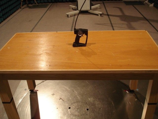
TEST REPORT Report No. : AG023092-001 Date : 2006 September 25 Page 1 of 11 FCC ID: PIYK7238-07A4T This document shall not be reproduced except in full or with written approval by the laboratory. CMA Industrial Development Foundation Limited Room 1302, Yan Hing Centre, 9-13 Wong Chuk Yeung St.., Fo Tan, Shatin, Hong Kong. Tel: (852) 2698 8198 Fax: (852) 2695 4177 E-mail: [email protected] Web Site: http://www.cmatcl.com Application No. : LG219638(7) Client: Mattel Asia Pacific Sourcing Limited 13/F., South Tower, World Finance Centre, Harbour City, Tsim Sha Tsui, Kowloon, Hong Kong Applicant : Sample Description : One(1) submitted sample(s) stated to be Dune Devil Pro of Model No. K7238 Radio Frequency : 49.860MHz Transmitter Rating : 2 x 1.5V AA size batteries No. of submitted sample : Two(2)piece(s) *** Date Received : 2006 August 23 Test Period : 2006 August 30 – 2006 September 19 Test Requested : FCC Part 15 Certification. Test Method : 47 CFR Part 15 (10-1-05 Edition) ANSI C63.4 – 2003 Test Result : See attached sheet(s) from page 2 to 11. Conclusion : The submitted sample was found to comply with requirement of FCC Part 15 Subpart C. For and on behalf of CMA Industrial Development Foundation Limited Authorized Signature : ____________________________________________________ Danny Chui Deputy Manager - EL. Division TEST REPORT Report No. : AG023092-001 Date : 2006 September 25 Page 2 of 11 FCC ID: PIYK7238-07A4T This document shall not be reproduced except in full or with written approval by the laboratory. CMA Industrial Development Foundation Limited Room 1302, Yan Hing Centre, 9-13 Wong Chuk Yeung St.., Fo Tan, Shatin, Hong Kong. Tel: (852) 2698 8198 Fax: (852) 2695 4177 E-mail: [email protected] Web Site: http://www.cmatcl.com Table of Contents 1 General Information............................................................................................................................. 3 1.1 General Description ..................................................................................................................... 3 1.2 Location of the test site ................................................................................................................ 4 1.3 List of measuring equipment........................................................................................................ 5 2 Description of the radiated emission test ............................................................................................. 6 2.1 Test Procedure ............................................................................................................................. 6 2.2 Test Result ................................................................................................................................... 6 2.3 Radiated Emission Measurement Data ........................................................................................ 7 3 Description of the Line-conducted Test............................................................................................... 8 3.1 Test Procedure ............................................................................................................................. 8 3.2 Test Result ................................................................................................................................... 8 3.3 Graph and Table of Conducted Emission Measurement Data ..................................................... 8 4 Photograph ........................................................................................................................................... 9 4.1 Photographs of the Test Setup for Radiated Emission and Conduction Emission....................... 9 4.2 Photographs of the External and Internal Configurations of the EUT......................................... 9 5 Supplementary document................................................................................................................... 10 5.1 Bandwidth .................................................................................................................................. 10 5.2 Duty cycle .................................................................................................................................. 10 5.3 Transmission time ...................................................................................................................... 10 6 Appendices......................................................................................................................................... 11 TEST REPORT Report No. : AG023092-001 Date : 2006 September 25 Page 3 of 11 FCC ID: PIYK7238-07A4T This document shall not be reproduced except in full or with written approval by the laboratory. CMA Industrial Development Foundation Limited Room 1302, Yan Hing Centre, 9-13 Wong Chuk Yeung St.., Fo Tan, Shatin, Hong Kong. Tel: (852) 2698 8198 Fax: (852) 2695 4177 E-mail: [email protected] Web Site: http://www.cmatcl.com 1 General Information 1.1 General Description The equipment under test (EUT) is a transmitter for Dune Devil Pro. It operates at 49.86MHz in which is controlled by a crystal. The EUT is powered by 2 x 1.5V “AA” size batteries, and it has two control trigger in the EUT. When the forward, backward, turn left and turn right trigger is pressed once, it will transmit a different radio signal to receiver. The brief circuit description is saved with filename: OpDes.pdf TEST REPORT Report No. : AG023092-001 Date : 2006 September 25 Page 4 of 11 FCC ID: PIYK7238-07A4T This document shall not be reproduced except in full or with written approval by the laboratory. CMA Industrial Development Foundation Limited Room 1302, Yan Hing Centre, 9-13 Wong Chuk Yeung St.., Fo Tan, Shatin, Hong Kong. Tel: (852) 2698 8198 Fax: (852) 2695 4177 E-mail: [email protected] Web Site: http://www.cmatcl.com 1.2 Location of the test site Radiated emissions measurements are investigated and taken pursuant to the …
Text truncated - open the document above for the full version.
Test Report
Job No.: _______________ WF-EL-EMC-15 Edition 1 2006 April 12 Page of Bandwidth Plot Bandwidth 1
Test Report
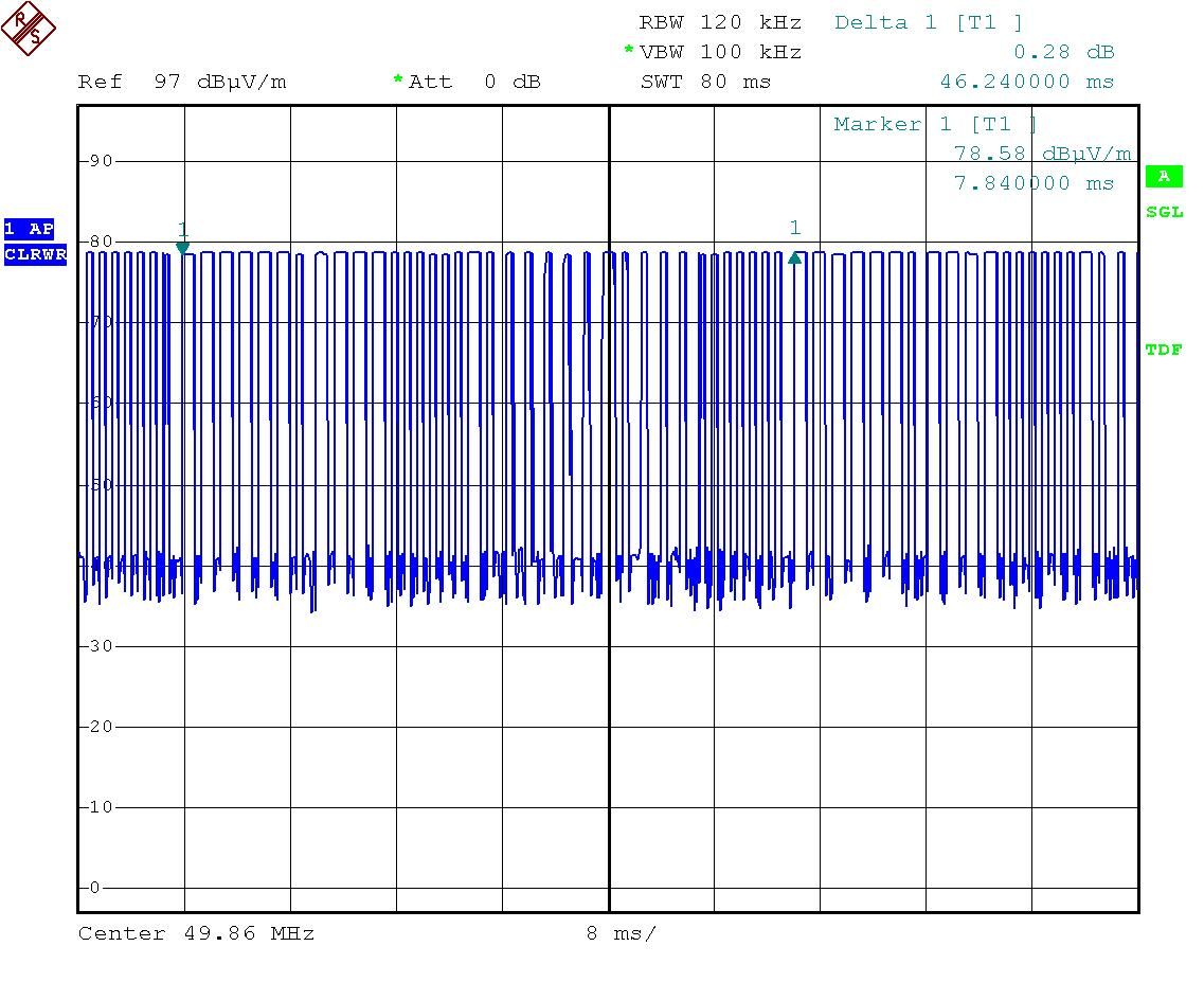
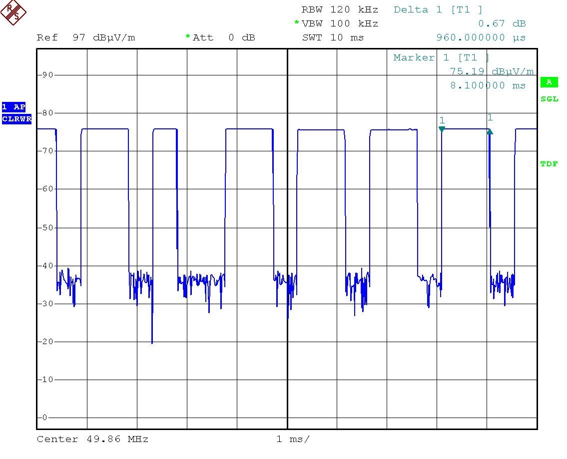
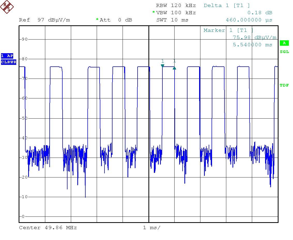
Job No.: _______________ WF-EL-EMC-15 Edition 1 2006 April 12 Page of Duty Cycle Duty Cycle 1 Duty Cycle 2 Job No.: _______________ WF-EL-EMC-15 Edition 1 2006 April 12 Page of Duty Cycle 3
Contact Information
Applicant
Joule Mak(Director, Electronic Engineering)
Test Firm
CMA Industrial Development Foundations LimitedStephen Lam
Technical Specifications
| # | Rule Parts | Frequency Range | Power Output |
|---|---|---|---|
| 1 | 15C | 49.86 MHz - 49.86 MHz | - |
Other Applications from Mattel Asia Pacific Sourcing Ltd.
PIY-HTX00-24-A5T
Jan 17, 2024Fisher-Price Link Squad Jam & Count Panda
Equipment Class
DXX - Part 15 Low Power Communication Device TransmitterPIY-HTX03-24-A5T
Jan 17, 2024Fisher-Price Link Squad A to Z Yak
Equipment Class
DXX - Part 15 Low Power Communication Device TransmitterPIY-HTX04-24-A5T
Jan 17, 2024Fisher-Price Link SquadBop & Groove Tiger
Equipment Class
DXX - Part 15 Low Power Communication Device TransmitterPIY-HTW99-24-A5T
Jan 17, 2024Fisher-Price Link Squad Opposites Fox
Equipment Class
DXX - Part 15 Low Power Communication Device TransmitterPIY-HTX01-24-A5T
Jan 17, 2024Fisher-Price Link Squad Crawl n Colors Chameleon
Equipment Class
DXX - Part 15 Low Power Communication Device Transmitter