PIYK8880-06A4RJEEP HURRICANE RE-DECO
Mattel Asia Pacific Sourcing Ltd.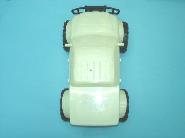
Click to zoom
Application Details
- Equipment Class
- CRR - Superregenerative Receiver
- Date of Grant
- Oct 09, 2006
- Application Purpose
- Original Equipment
- Date of Application
- Oct 09, 2006
- Equipment Note
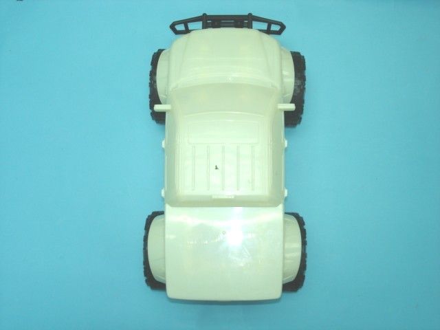
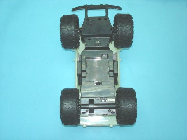
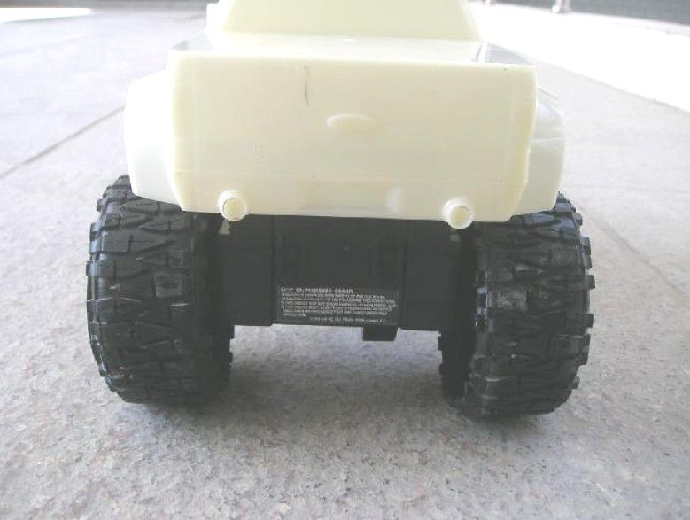
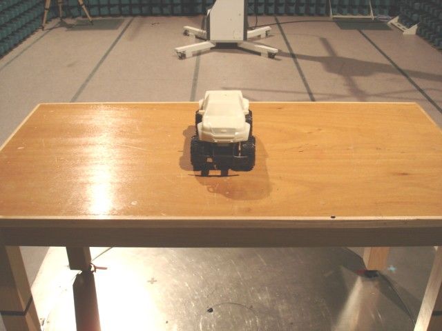
- JEEP HURRICANE RE-DECO
- Frequency Range
- 49.86000000 - 49.86000000
- Country
- Hong Kong
Documents & Files
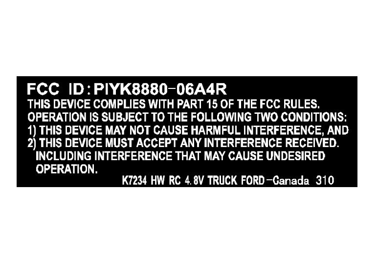
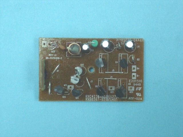
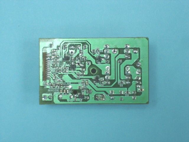
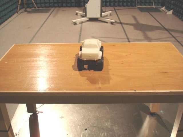
Document Text
Text extracted from the exhibit documents filed with the FCC. Open a document above to read the original.
Users Manual
Keep these instructions for future reference: they contain important information. I. CONTENTS • Vehicle • Transmitter • 2 AA Batteries (if supplied) • 4.8V Jet Turbo® Battery Pack (if supplied) • 4.8V Jet Turbo® Charger (if supplied) Please check the package for the specific power system for this vehicle: Vehicles use the Tyco® R/C 4.8V Jet Turbo® rechargeable NiCd Battery Pack & Charger. You’ll find detailed information about all these power systems in this Owner’s Manual. For information about the 4.8V Jet Turbo® NiCd power system, please refer to Section VI. II. CHASSIS Your vehicle’s chassis will look like one of the chassis shown, depending on the vehicle’s design. ❶ Battery latch ❷ ON/OFF switch ❸ Steering adjuster Refer to label on transmitter and vehicle for frequency. Do not race vehicles with the same frequency. III. VEHICLE OPERATION ❶ FORWARD ❷ REVERSE ❸ LEFT ❹ RIGHT CAUTION: Surfaces may become hot and cause burns if electronics get wet. Do not operate vehicle through water or snow. FORWARDREVERSE LEFT RIGHT w r y e q t ❶ ❷ ❸ ® Hot Wheels ® R/C SUPPORT Questions or problems with your product? DON’T RETURN IT TO THE STORE! Just call us for help. U.S. consumers may also register their products at this number. 1-888-557-8926 ASST.K8517 K7231/32/33/34-0920 IV. TRANSMITTER Transmitters are equipped with a special automatic ON battery-saving feature. Just turn your vehicle ON. Then push either transmitter stick and you will be able to run and control your vehicle. TRANSMITTER 1. To install the transmitter battery, open the battery cover as shown. 2. Install 2 AA batteries with polarity (+/-) as shown inside the battery compartment. 3. Replace the battery cover. V. POWER CLIP Please check the package for the specific power system for this vehicle: Vehicles use the Tyco® R/C 4.8V Jet Turbo® rechargeable NiCd Battery Pack & Charger. For detailed information regarding NiCd battery charging and safety, please follow the specific instructions that came with your battery pack and charger. VEHICLE BATTERY INSTALLATION These instructions apply to the 4.8V Jet Turbo® rechargeable NiCd Battery Pack. 1. Rotate the battery latch to the open position. 2. Insert the rechargeable NiCd battery pack) into the battery compartment and slide it away from the latch. 3. Make sure the rechargeable NiCd battery pack) snaps securely in place. Rotate the latch to the locked position. 4. To remove: turn the latch, slide it toward the latch and lift it out. VI. 4.8V JET TURBO® NiCd 1. Rotate the battery latch to the open position. 2. Insert the battery pack into the battery compartment and slide it away from the latch. 3. Make sure the battery pack snaps securely in place and rotate the latch to the locked position. 4. To remove the battery pack: turn the latch, slide the battery pack toward the latch and lift it out. BATTERY CHARGING/CARE – 4.8V JET TURBO® BATTERY X CAUTION: Use only the charger supplied with this toy. Do not use any other charging source. 1. Plug the wall pack charger into a standard wall outlet. 2. Click the battery pack into the charger. Make certain the battery pack is secure in the charger. 3. To disconnect, push the red button on the side of charger and simultaneously slide the battery pack out. 4. After charging, the battery will feel warm. This condition is normal for fully charged batteries. 5. New battery packs must be charged for 10 hours the first two times charged. Subsequent charges will require 6 hours. Charging the battery pack for more than 6 hours will not give you a longer running time. 6 hours is all that is required for a fully charged battery pack. 6. Unlike alkaline batteries, where the power loss is gradual, a NiCd battery will run for its normal running time and then lose most of its power at once. That's when you'll know it is time to recharge the battery pack. 2 xAA/LR6 7. After use, the battery pack will be hot! Wait at least 20 minutes until the battery pack cools before recharging. Recharging a warm or hot battery pack will greatly reduce the number of times your battery pack can be recharged. Charge only TYCO® R/C Jet Turbo® 4.8V NiCd 700 or 800mAh rechargeable battery packs. Other types of batteries may burst and causing injury to persons and damage. 8. The charger must be disconnected from the electric supply. w r y e q t 4.8V d.c. NiCd 1X4 "AA" w r y e q t w r y e q t CONSUMER INFORMATION Note to Adults: To ensure that the child’s play is both safe and fun, please review all operating instructions and safety rules with your child. SAFETY TIPS • NEVER drive your vehicle on streets! They’re for real cars! • DO NOT pick up vehicle while in motion. • Keep fingers, hair and loose clothing away from the tires and the wheel hubs while the vehicle is switched ON. X CAUTION: To prevent entanglement, keep hair away from wheels. • Adult supervision is recommended when this vehicle is being operated. • To avoid accidental operation, remove all batteries when not in use. Always turn the vehicle OFF before removing batteries. BATTERY SAFETY INFORMATION In exceptional circumstances batteries may leak fluids that can cause a chemical burn injury or ruin your toy (product). To avoid battery leakage: • Non-rechargeable batteries are not to be recharged. • Rechargeable batteries are to be removed from the toy before being charged (if designed to be removable). • Rechargeable batteries are only to be charged under adult supervision (if designed to be removable). • Do not mix alkaline, standard (carbon-zinc), or rechargeable (nickel-cadmium) batteries. • Do not mix old and new batteries. • Only batteries of the same or equivalent type as recommended are to be used. • Batteries are to be inserted with the correct polarity. • Exhausted batteries are to be removed from the toy. • The supply terminals are not to be short-circuited. • Dispose of battery(ies) safely. • Do not dispose of this toy in a fire. The batteries inside may explode or leak. Battery Performance Note: For best pe…
Text truncated - open the document above for the full version.
Operational Description
Mattel # k8880 RX 49. 860 MHz Receiver Operational Description The 4.8V car & Truck is full function radio controlled toy car It operates on 4.8 volts supplied by 4.8V Nicad battery pack It is designed to operate on a single fixed frequency in the 49.82 – 49.90 MHz band. See the attached block diagram and schematic. The vehicle receiver receives and demodulates the AM transmitted signal from the transmitter, using a standard super-regenerative AM receiver/demodulator circuit comprised of ANT1, Q1, L1, L3, L4 and associated passive components. L4 is a tunable core slug inductor that is used to tune the receiver for maximum sensitivity. The output of the AM receiver/demodulator is AC coupled to a high input impedance CMOS inverter is connected to the U1 decoder IC, it is biased into their linear region through C12, C14, C9, R4, R13, R6, R7 and function as amplify, filter and shape the data. After passing through the last inverter stage, the incoming waveform is a digitized enough to be fed into the IN1 pin for on-chip decoding. A Zener regulator circuit comprised of C11, C13, R3, D1, C8, C15, it supplied voltage VDD for the super-regenerati ve radio, decoder IC. Drive motor is controlled by the U1 decoder IC, low power switching transistors Q6, Q7, and a high power H-bridge comprised of Q4, Q5, Q8, Q9, The Steering Motor is controlled by the U1 decoder IC low power switching transistors Q12,Q14,and a high power H-bridge comprised of Q10,Q11,Q13,Q15, All tuning and verifications are performed by the manufacturer and there are no adjustments which can be made by the user. No external ground is required or used with this receiver.
Schematics
PDF created with pdfFactory trial version www.pdffactory.com
Test Report
TEST REPORT Report No. : AG025387-001 Date : 2006 October 10 Page 1 of 11 FCC ID: PIYK8880-06A4R This document shall not be reproduced except in full or with written approval by the laboratory. CMA Industrial Development Foundation Limited Room 1302, Yan Hing Centre, 9-13 Wong Chuk Yeung St.., Fo Tan, Shatin, Hong Kong. Tel: (852) 2698 8198 Fax: (852) 2695 4177 E-mail: [email protected] Web Site: http://www.cmatcl.com Application No. : LG218134(8) Client : Mattel Asia Pacific Sourcing Limited 13/F., South Tower, World Finance Centre, Harbour City, Tsim Sha Tsui, Kowloon, Hong Kong Sample Description : One(1) submitted sample(s) stated to be JEEP Hurricane RE-DECO of Model No. K8880 Radio Frequency : 49.860MHz Receiver Rating : 1 x 4.8V rechargeable battery No. of submitted sample : Three (3) piece(s) *** Date Received : 2006 September 29 Test Period : 2006 September 29 – 2006 October 10 Test Requested : FCC Part 15 Certification. Test Method : 47 CFR Part 15 (10-1-05 Edition) ANSI C63.4 – 2003 Test Result : See attached sheet(s) from page 2 to 11. Conclusion : The submitted sample was found to comply with requirement of FCC Part 15 Subpart B. For and on behalf of CMA Industrial Development Foundation Limited Authorized Signature : ____________________________________________________ Danny Chui Deputy Manager - EL. Division TEST REPORT Report No. : AG025387-001 Date : 2006 October 10 Page 2 of 11 FCC ID: PIYK8880-06A4R This document shall not be reproduced except in full or with written approval by the laboratory. CMA Industrial Development Foundation Limited Room 1302, Yan Hing Centre, 9-13 Wong Chuk Yeung St.., Fo Tan, Shatin, Hong Kong. Tel: (852) 2698 8198 Fax: (852) 2695 4177 E-mail: [email protected] Web Site: http://www.cmatcl.com Table of Contents 1 General Information............................................................................................................................. 3 1.1 General Description ..................................................................................................................... 3 1.2 Location of the test site ................................................................................................................ 4 1.3 List of measuring equipment........................................................................................................ 5 2 Description of the radiated emission test ............................................................................................. 6 2.1 Test Procedure ............................................................................................................................. 6 2.2 Test Result ................................................................................................................................... 6 2.3 Radiated Emission Measurement Data ........................................................................................ 7 3 Description of the Line-conducted Test............................................................................................... 8 3.1 Test Procedure ............................................................................................................................. 8 3.2 Test Result ................................................................................................................................... 8 3.3 Graph and Table of Conducted Emission Measurement Data ..................................................... 8 4 Photograph ........................................................................................................................................... 9 4.1 Photographs of the Test Setup for Radiated Emission and Conduction Emission....................... 9 4.2 Photographs of the External and Internal Configurations of the EUT......................................... 9 5 Supplementary document................................................................................................................... 10 5.1 Bandwidth .................................................................................................................................. 10 5.2 Duty cycle .................................................................................................................................. 10 5.3 Transmission time ...................................................................................................................... 10 6 Appendices......................................................................................................................................... 11 TEST REPORT Report No. : AG025387-001 Date : 2006 October 10 Page 3 of 11 FCC ID: PIYK8880-06A4R This document shall not be reproduced except in full or with written approval by the laboratory. CMA Industrial Development Foundation Limited Room 1302, Yan Hing Centre, 9-13 Wong Chuk Yeung St.., Fo Tan, Shatin, Hong Kong. Tel: (852) 2698 8198 Fax: (852) 2695 4177 E-mail: [email protected] Web Site: http://www.cmatcl.com 1 General Information 1.1 General Description The equipment under test (EUT) is a super regenerative receiver for JEEP Hurricane RE-DECO. It operates at 49.860MHz which is controlled by LRC circuit. The EUT is powered by 1 x 4.8V rechargeable battery. When received a forward, backward, turn right or turn left signal, it will run to the corresponding direction. The brief circuit description is listed as follows: - Q1 and associated circuit act as RF receiver. - U1 and associated circuit act as decoder. - Q10 ~ Q15 and associated circuit act as M1 motor control. - Q4 ~Q9 and associated circuit act as M2 motor control. TEST REPORT Report No. : AG025387-001 Date : 2006 October 10 Page 4 of 11 FCC ID: PIYK8880-06A4R This document shall not be reproduced except in full or with written approval by the laboratory. CMA Industrial Development Foundation Limited Room 1302, Yan Hing Centre, 9-13 Wong Chuk Yeung St.., Fo Tan, Shatin, Hong Kong. Tel: (852) 2698 8198 Fax: (852) 2695 4177 E-mail:…
Text truncated - open the document above for the full version.
Contact Information
Applicant
Joule Mak(Director, Electronic Engineering)
Test Firm
CMA Industrial Development Foundations LimitedStephen Lam
Technical Specifications
| # | Rule Parts | Frequency Range | Power Output |
|---|---|---|---|
| 1 | 15B | 49.86 MHz - 49.86 MHz | - |
Other Applications from Mattel Asia Pacific Sourcing Ltd.
PIY-HTX00-24-A5T
Jan 17, 2024Fisher-Price Link Squad Jam & Count Panda
Equipment Class
DXX - Part 15 Low Power Communication Device TransmitterPIY-HTX03-24-A5T
Jan 17, 2024Fisher-Price Link Squad A to Z Yak
Equipment Class
DXX - Part 15 Low Power Communication Device TransmitterPIY-HTX04-24-A5T
Jan 17, 2024Fisher-Price Link SquadBop & Groove Tiger
Equipment Class
DXX - Part 15 Low Power Communication Device TransmitterPIY-HTW99-24-A5T
Jan 17, 2024Fisher-Price Link Squad Opposites Fox
Equipment Class
DXX - Part 15 Low Power Communication Device TransmitterPIY-HTX01-24-A5T
Jan 17, 2024Fisher-Price Link Squad Crawl n Colors Chameleon
Equipment Class
DXX - Part 15 Low Power Communication Device Transmitter