PIYK8888-06A4RR/C SQUADRON
Mattel Asia Pacific Sourcing Ltd.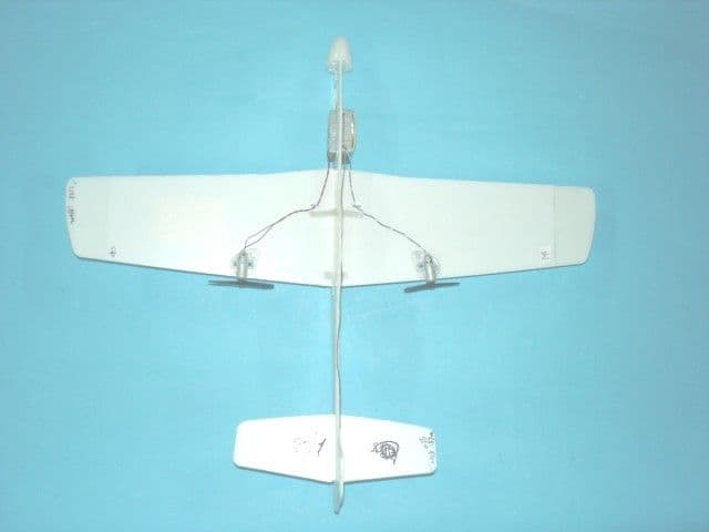
Click to zoom
Application Details
- Equipment Class
- CRR - Superregenerative Receiver
- Date of Grant
- Oct 24, 2006
- Application Purpose
- Original Equipment
- Date of Application
- Oct 24, 2006
- Equipment Note
- R/C SQUADRON
- Frequency Range
- 49.86000000 - 49.86000000
- Country
- Hong Kong
Documents & Files
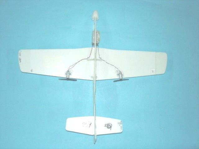
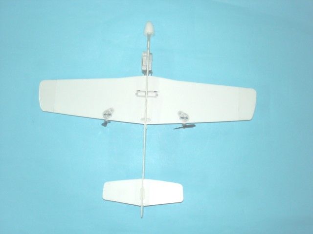
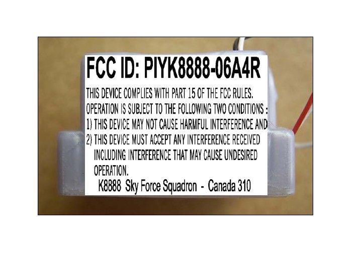
Document Text
Text extracted from the exhibit documents filed with the FCC. Open a document above to read the original.
Users Manual
BUILD IT! POWER IT! A WHIP ANTENNA CONTROL STICK (POWER) SIGNAL INDICATOR CHARGE INDICATOR CONTROL STICK (LEFT & RIGHT) ON (I) OFF (0) CHARGER( ) ON (I) OFF (0) CHARGER( ) O I B C D 75'/25m playing area I O O I ON OFF PROPELLERS CHARGER SLOT PROPELLERS WIRE ANTENNA WIRE ANTENNA ON (I) / OFF (0) SWITCH O I O I O I A B C D TOP VIEWSTOP VIEWS BOTTOM VIEWBOTTOM VIEW TOP VIEWSTOP VIEWS BOTTOM VIEWBOTTOM VIEW TOP VIEWTOP VIEW BOTTOM VIEWBOTTOM VIEW TOP VIEW BOTTOM VIEW TOP VIEW BOTTOM VIEW TOP VIEW BOTTOM VIEW TOP VIEWS TOP VIEWS BOTTOM VIEWBOTTOM VIEW TOP VIEWSTOP VIEWS BOTTOM VIEWBOTTOM VIEW TOP VIEWTOP VIEW BOTTOM VIEWBOTTOM VIEW TOP VIEW BOTTOM VIEW TOP VIEW BOTTOM VIEW TOP VIEW BOTTOM VIEW a. a. a. b. b. b. c. c. 1. 1. 2. 2. 3. 3. 4. 4. 5. 5. 7. 8. 6. LEFT RIGHT WIND RIGHT Upside down view Bi-PLANE ASSEMBLY SINGLE WING PLANE ASSEMBLY SAFETY INFORMATION Adults, this toy is recommended for children 8 years of age and older. To ensure that the child’s play is both safe and fun, please review the operating instructions and these general safety rules with the child. • Keep fingers, hair and loose clothing away from the propellers while the plane is switched ON. • Adult supervision is recommended when the plane is being operated. • To avoid accidental operation, remove all removable batteries when not in use and turn off the plane. • If the plane and/or charger get wet, discontinue use until they are completely dry. Thoroughly wipe off all moisture and allow them to air-dry completely before use. • DO NOT fly in the street! Make sure you have plenty of open space in all directions. • Regularly inspect the antenna for cracks or breaks. DO NOT bend the transmitter antenna when extended. DO NOT use the transmitter if the antenna is broken. • The wire antenna is fragile. Never pull or tug on the antenna, as it may loosen or detach from the plane. Never coil or knot the antenna. • Use only the charger supplied with this toy, do not use any other charging source. 1. Radio interference can make the plane fly poorly. Interference can be caused by other R/C vehicles running on the same frequency, electrical wires, large buildings, or CB radios. Try to stay away from these! 2. Flying time may change depending on air conditions and on your flying style. When the plane fails to respond, slows down, or loses range, recharge it. If performance does not improve following a recharge, install fresh alkaline batteries in the charger. 3. For the greatest range, make sure the transmitter antenna is pointed up...and make sure the wire antenna on the plane is straight and dangling. 4. Because the plane is sensitive to extra weight, dirt or mud on the plane can affect its operation. Use a clean dry cloth to remove any dirt or mud immediately. If the plane gets wet, it's important not to operate it until it's completely dry, inside and outside. Wipe surfaces with a towel and allow the plane to air-dry until it's dry...overnight at least. 5. Do not store the plane near heat or in direct sunlight. Always turn switches OFF and remove all removable batteries for storage. Gliding: Remove the Power Pack™ System and replace with the center weight. Orient the plug into the plane so that the weight is to the REAR for the Bi-plane and towards the front for the single wing planes. Gently throw the glider in as straight a line as possible. See how far it'll go! ® ASST. K7256 K8887/88/L5512/13-0920 It takes a little time and practice to become an ace pilot. If you still have difficulty flying the plane, please check this troubleshooting guide. Usually the problem is a simple one...with a quick solution. 1. Check all removable batteries. Make sure connections are secure. You may need to replace the transmitter battery, and/or the charger batteries, with fresh alkaline batteries. 2. Check air conditions. DO NOT attempt to operate the plane in in windy conditions. 3. Check antennas. Make sure the wire antenna is straight and dangling below the plane. 4. Check the plane for dirt or mud and clean it if necessary. 5. After landing, make sure the wing and fuselage assemblies are properly aligned. 6. Check that the Power Pack™ System motors are perpendicular to the wing. 7. If the propellers on the plane spin with no signal from the transmitter, turn off the Power Pack™ System and relocate to an area with no signal interference. 8. When you first take off, if the plane is turning to the right without your steering the plane then you need to turn the left propeller away from the fuselage. Try flying the plane again and repeat as necessary until you achieve straight level flight. If the plane is making a left hand turn you will need to turn the right propeller away from the fuselage. 9. TRIM: If the plane does not fly straight, you can adjust the motor angles on the plane to achieve straight flight. If the plane veers to the right, rotate the LEFT motor/propeller inward. If the plane veers to the left, rotate the RIGHT motor/propeller inward. CONTENTS/FEATURES Bi-Plane Mustang Rescue Plane Fighter/Assault 8+ The transmitter’s control sticks operate the engines of the PLANE. THROTTLE CONTROLS Press the LEFT control stick up to increase the power level. When you release the control stick, the engines will stop and the plane will glide. The RIGHT control stick operates steering. Push LEFT to steer LEFT. Push RIGHT to steer RIGHT. READY TO FLY FLIGHT TIPS FOR BEGINNERS TROUBLESHOOTING CONTROL STICKS AND BUTTONS QUICK TIPS 1. 4.5. 2. 3. The Power Pack™ system is powered by an internal LiPo battery that is permanently installed. It must be charged before using. To charge, first make sure you have installed 6 "AA" (LR6) alkaline batteries in the TRANSMITTER/CHARGER as shown earlier. Then follow these easy steps: 1. Make sure both Power Pack™ system power switch and the TRANSMITTER/CHARGER are in the OFF position. 2. Open the door on the TRANSMITTER/CHARGER as shown. 3. Plug the TRANSMITTER/CHARGER’S wire connector into the PLANE as shown. Make sur…
Text truncated - open the document above for the full version.
Block Diagram
1 2 34 ABCD 4 3 2 1 D CBA Title Number Revision Size A4 Date: 16-Oct-2006 Sheet of File: D:\hbpe42\..\K8888 RX BLOCK DIAGRAM.sch Drawn By: M2M1 ANTENNA Voltage Regulater Super Regenerative Circiut U1 Q5 U3 Signal Amplifier Decoder Decoder Motor Driver CircuitMotor Driver Circuit BLOCK - DIAGRAM K8888 Receiver 49.860MHz MAIN PCB :PIYK8888-06A4R Q3 Q4 Li Po Battery Pack 3.7V Profile Plane (MATTEL) K8888 00 11 PCM Battery Protect IC S-8261 A08820 Circuit
Operational Description
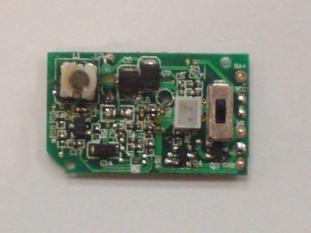
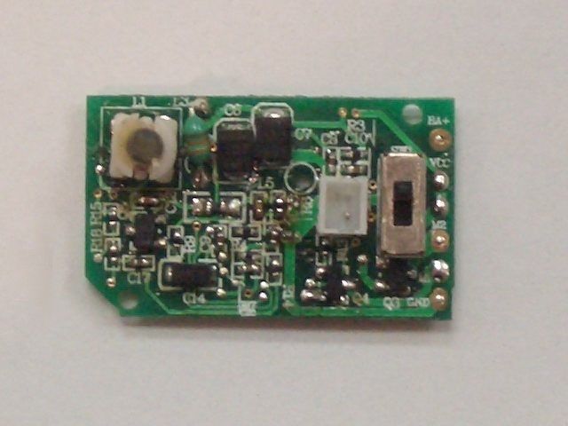
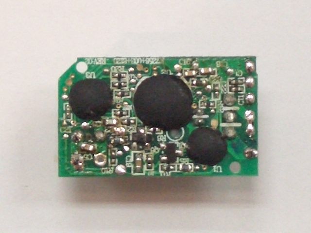
Profile Plane #K8888 49.860MHz RECEIVER OPERATIONAL DESCRIPTION The Profile Plane is a full function RF remote control toy plane. It uses a 3.7 volts LiPo battery as power supply. It is designed to operate on a single fixed frequency in 49.82 MHz - 49.90MHz band.Refer to the attached block diagram and schematic. The modulated RF signal which transmits from the transmitter including the code signal is received by the Profile Plane’s permanently external antenna. The electrical signal is amplified selectively by a super regenerative circuit. (Q5,L1,,L3.L5,C3,C5,C13,C13,C14)The demodulate signal is coupled into an integrated circuit(U3)by R4 and C15,which the signal is amplified further and decoded, Five pins of U3 output the code to drive IC(U2),The PIN PWML and PIN PWMR of U2 are used for driving the MOSFET(Q3,Q4) to control the direction o f two motors. The function of the integrated circuit(U1) is regulating the circuit voltage. All tuning and verifications are performed by the manufacturer and there are no adjustments that can be made by the user. No external ground is required or used with this receiver.
Schematics
1 2 3 4 56 ABCD 6 5 4 3 2 1 D CBA Title Number Revision Size B Date: 20-Oct-2006 Sheet of File: C:\Documents and Settings\pe.JETTA\ 桌面 \RX(FOR PP 49M).DDB Drawn By: M2 Li po battery M1 SW1 R12 5.6k R135.6K VCC C21 100pF R10 200K R18 3.3M R15 3.3K R143.3K R17 3.3M C20 100pF C170.1uF C150.1uF C10 0.047uF C8 0.01uF + C6 100uF R32.2K R2 2.2K L1 7.5T C5 5pF Q5 2SC2712 C12 22pF C90.01uF + C14 4.7uF R9 270K L5 3.3uH R8680 C13 2200pF R4 2.2K CHARGER 3.0V VCC 2.7V Profile Plane (MATTEL) C7 100uF INL OUT1IN2OUT2 DIN Q3 CES2304 Q4CES2304 D10 5 D11 6 D12 8 D13 9 D14 10 VSS 1 DIN 4 INL 11 OUT1 12 IN2 13 OUT2 14 VDD 7 ROSC 2 U3 SPRC206A Left Motor Right Motor R21 1K R221K R16 1K R19 1K R20 1K C22 0.1uF 3.0V 0, 0 0, 11, 01, 1 DISABLE 65 SI2 2 SI1 3 SI0 4 LEFT 1 RIGHT 72 OP1 70 OP2 71 OSCI 62 OSCO 61 VDD 25 PWMR 54 PWMR 55 PWML 56 PWML 57 VSS 60 U2 R23 160K C16 100pF C18100pF L3 2.2uH C35pF ANT C11 0.1uF C1 0.1uF V- 2 Ct 4 Vss 6 Dout 1 Cout 3 VDD 5 G1 5 S1 6 S1 7 D1 8 G2 4 S2 3 S2 2 D2 1 R12k C4 0.1uF R5470 S-8261 AO 8820 VIN 2 GND 1 VOUT 3 LVDB 4 U1 SPY0029A K8888 (49MHz RX) 01 11 3.7V STK-K7256A PCM
Test Report
TEST REPORT Report No. : AG025419-001 Date : 2006 October 23 Page 1 of 11 FCC ID: PIYK8888-06A4R This document shall not be reproduced except in full or with written approval by the laboratory. CMA Industrial Development Foundation Limited Room 1302, Yan Hing Centre, 9-13 Wong Chuk Yeung St.., Fo Tan, Shatin, Hong Kong. Tel: (852) 2698 8198 Fax: (852) 2695 4177 E-mail: [email protected] Web Site: http://www.cmatcl.com Application No. : LG220910(3) Client : Mattel Asia Pacific Sourcing Limited 13/F., South Tower, World Finance Centre, Harbour City, Tsim Sha Tsui, Kowloon, Hong Kong Sample Description : One(1) submitted sample(s) stated to be R/C Squadron of Model No. K8888 Radio Frequency : 49.860 MHz Receiver Rating : 1 x 3.6V rechargeable battery No. of submitted sample : Two (2) piece(s) *** Date Received : 2006 September 22 Test Period : 2006 September 22 – 2006 October 04 Test Requested : FCC Part 15 Certification. Test Method : 47 CFR Part 15 (10-1-05 Edition) ANSI C63.4 – 2003 Test Result : See attached sheet(s) from page 2 to 11. Conclusion : The submitted sample was found to comply with requirement of FCC Part 15 Subpart B. For and on behalf of CMA Industrial Development Foundation Limited Authorized Signature : ____________________________________________________ Danny Chui Deputy Manager - EL. Division TEST REPORT Report No. : AG025419-001 Date : 2006 October 23 Page 2 of 11 FCC ID: PIYK8888-06A4R This document shall not be reproduced except in full or with written approval by the laboratory. CMA Industrial Development Foundation Limited Room 1302, Yan Hing Centre, 9-13 Wong Chuk Yeung St.., Fo Tan, Shatin, Hong Kong. Tel: (852) 2698 8198 Fax: (852) 2695 4177 E-mail: [email protected] Web Site: http://www.cmatcl.com Table of Contents 1 General Information............................................................................................................................. 3 1.1 General Description ..................................................................................................................... 3 1.2 Location of the test site ................................................................................................................ 4 1.3 List of measuring equipment........................................................................................................ 5 2 Description of the radiated emission test ............................................................................................. 6 2.1 Test Procedure ............................................................................................................................. 6 2.2 Test Result ................................................................................................................................... 6 2.3 Radiated Emission Measurement Data ........................................................................................ 7 3 Description of the Line-conducted Test............................................................................................... 8 3.1 Test Procedure ............................................................................................................................. 8 3.2 Test Result ................................................................................................................................... 8 3.3 Graph and Table of Conducted Emission Measurement Data ..................................................... 8 4 Photograph ........................................................................................................................................... 9 4.1 Photographs of the Test Setup for Radiated Emission and Conduction Emission....................... 9 4.2 Photographs of the External and Internal Configurations of the EUT......................................... 9 5 Supplementary document................................................................................................................... 10 5.1 Bandwidth .................................................................................................................................. 10 5.2 Duty cycle .................................................................................................................................. 10 5.3 Transmission time ...................................................................................................................... 10 6 Appendices......................................................................................................................................... 11 TEST REPORT Report No. : AG025419-001 Date : 2006 October 23 Page 3 of 11 FCC ID: PIYK8888-06A4R This document shall not be reproduced except in full or with written approval by the laboratory. CMA Industrial Development Foundation Limited Room 1302, Yan Hing Centre, 9-13 Wong Chuk Yeung St.., Fo Tan, Shatin, Hong Kong. Tel: (852) 2698 8198 Fax: (852) 2695 4177 E-mail: [email protected] Web Site: http://www.cmatcl.com 1 General Information 1.1 General Description The equipment under test (EUT) is a super regenerative receiver for R/C Squadron. It is operates at 49.860MHz which is controlled by LRC circuit with PCM control. The EUT is powered by 1 x 3.6V rechargeable battery. When received a forward, turn left or turn right signal, it will fly to corresponding direction. The brief circuit description is listed as follows: - Q5 and associated circuit act as RC amplify. - U2, U3 and associated circuit act as decoder. - A-8261, AO 8820 and associated circuit act as battery. TEST REPORT Report No. : AG025419-001 Date : 2006 October 23 Page 4 of 11 FCC ID: PIYK8888-06A4R This document shall not be reproduced except in full or with written approval by the laboratory. CMA Industrial Development Foundation Limited Room 1302, Yan Hing Centre, 9-13 Wong Chuk Yeung St.., Fo Tan, Shatin, Hong Kong. Tel: (852) 2698 8198 Fax: (852) 2695 4177 E-mail: [email protected] Web Site: http://www.cmatcl.com 1.2 Location of the tes…
Text truncated - open the document above for the full version.
Contact Information
Applicant
Joule Mak(Director, Electronic Engineering)
Test Firm
CMA Industrial Development Foundations LimitedStephen Lam
Technical Specifications
| # | Rule Parts | Frequency Range | Power Output |
|---|---|---|---|
| 1 | 15B | 49.86 MHz - 49.86 MHz | - |
Other Applications from Mattel Asia Pacific Sourcing Ltd.
PIY-HTX00-24-A5T
Jan 17, 2024Fisher-Price Link Squad Jam & Count Panda
Equipment Class
DXX - Part 15 Low Power Communication Device TransmitterPIY-HTX03-24-A5T
Jan 17, 2024Fisher-Price Link Squad A to Z Yak
Equipment Class
DXX - Part 15 Low Power Communication Device TransmitterPIY-HTX04-24-A5T
Jan 17, 2024Fisher-Price Link SquadBop & Groove Tiger
Equipment Class
DXX - Part 15 Low Power Communication Device TransmitterPIY-HTW99-24-A5T
Jan 17, 2024Fisher-Price Link Squad Opposites Fox
Equipment Class
DXX - Part 15 Low Power Communication Device TransmitterPIY-HTX01-24-A5T
Jan 17, 2024Fisher-Price Link Squad Crawl n Colors Chameleon
Equipment Class
DXX - Part 15 Low Power Communication Device Transmitter