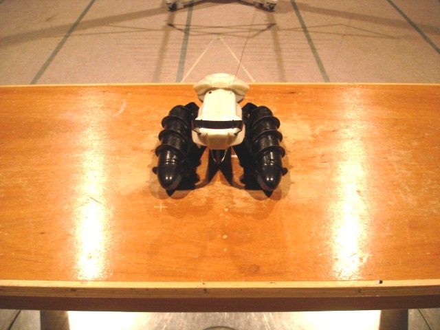
PIYX2875-12A4RTERRAIN TWISTER
Mattel Asia Pacific Sourcing Ltd.
Click to zoom
Application Details
- Equipment Class
- CRR - Superregenerative Receiver
- Date of Grant
- Feb 28, 2012
- Application Purpose
- Original Equipment
- Date of Application
- Feb 28, 2012
- Equipment Note
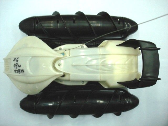
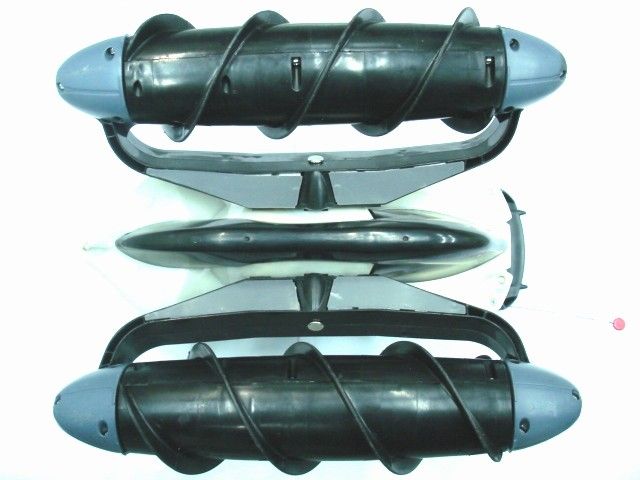
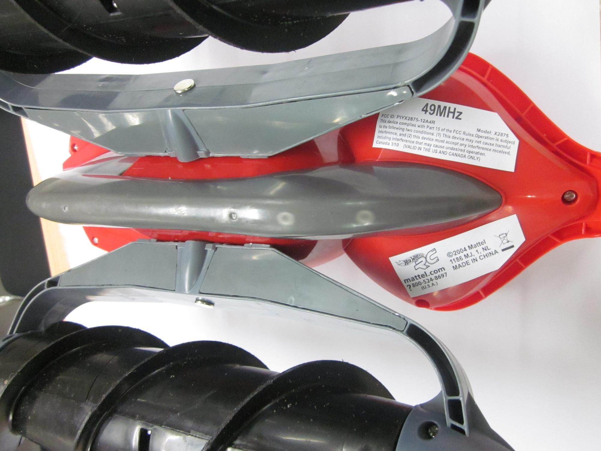
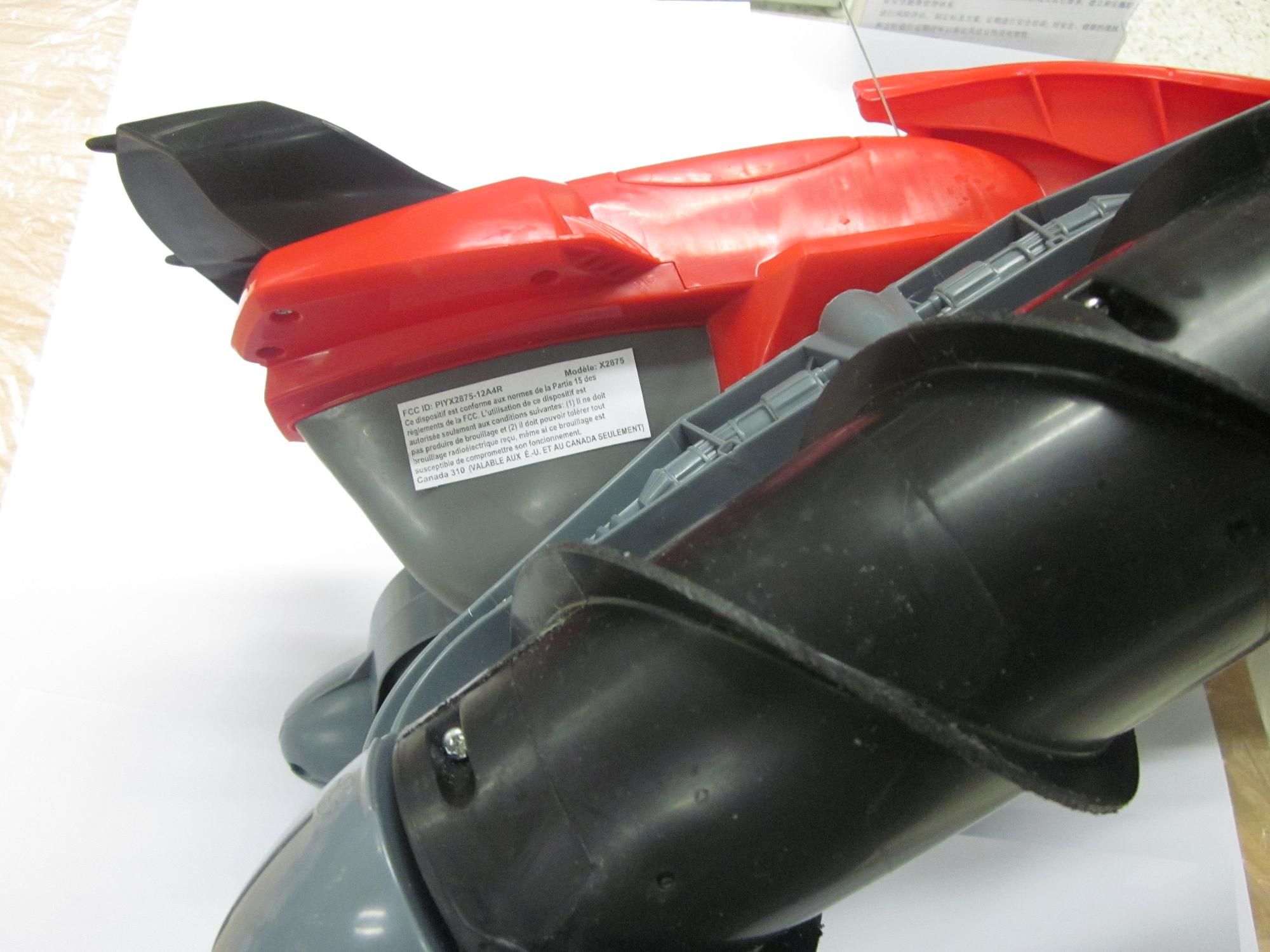
- TERRAIN TWISTER
- Frequency Range
- 49.86000000 - 49.86000000
- Country
- Hong Kong
Documents & Files
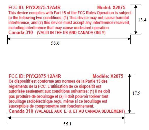
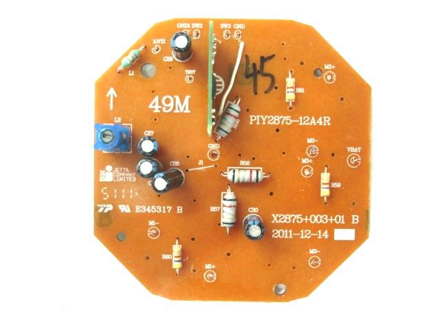
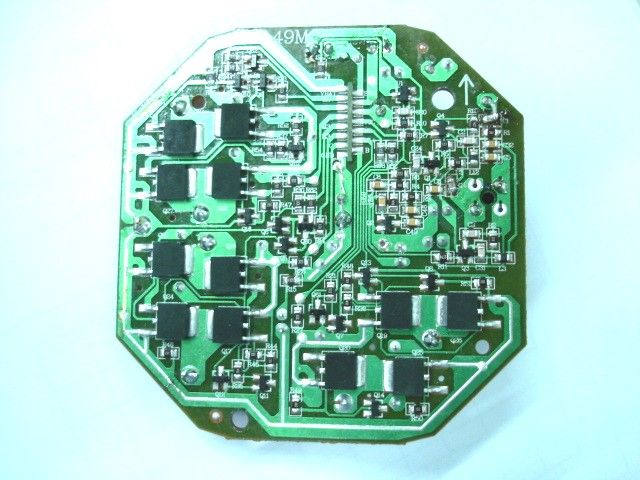
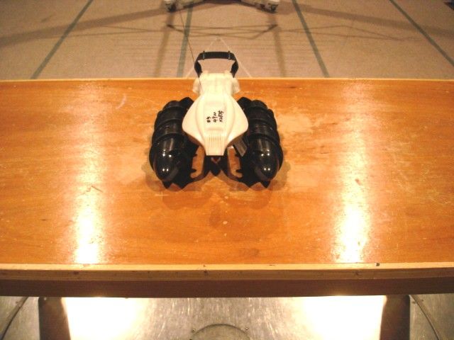
Document Text
Text extracted from the exhibit documents filed with the FCC. Open a document above to read the original.
Users Manual
q w 1 Vehicle 2 Transmitter I. CONTENTS/ FEATURES 1 Battery door 2 ON/OFF switch 3 Twin PowerScrews 1 Driving controls 2 Battery Door 3 Antenna SMART CIRCUITRY Your new vehicle is equipped with advanced “Smart Circuitry” designed to protect its electronic components under extreme operating conditions. If your vehicle stalls or gets stuck during use, it will automatically power down. Simply release the transmitter controls for a few seconds, then press the left control to resume normal operation. NOTE: When your vehicle powers up again, you may notice some movement of the vehicle body and the PowerScrews. This may also happen if the vehicle is switched off with the PowerScrews angled, and then turned back on. This is completely normal: it’s an automatic system designed to return the vehicle to normal driving position. Once the movement has stopped, you may simply resume normal operation. CAUTION: Surfaces may become hot and cause burns if electronics get wet. Do not operate vehicle through water or snow. CAUTION: To prevent entanglement, keep all hair away from moving parts. ™™ 2 1 2 1 1 3 3 3 8+ Keep these instructions for future reference as they contain important information. IMPORTANT: Please read all “Consumer Information” before operating your vehicle. CAUTION – ELECTICALLY OPERATED PRODUCT: Not recommended for children under [specify age grade] years of age. As with all electric products, precautions should be observed during handling and use to prevent electric shock. Asst. X2874 X2875/ X2876-0920 ® ©2012 Mattel. All Rights Reserved. Mattel, Inc., 636 Girard Avenue, East Aurora, NY 14052, U.S.A. Consumer Relations 1-888- 557-8926. Mattel U.K. Ltd., Vanwall Business Park, Maidenhead SL6 4UB. Helpline 01628 500303. Mattel Australia Pty., Ltd., Richmond, Victoria. 3121.Consumer Advisory Service - 1300 135 312. Mattel East Asia Ltd., Room 1106, South Tower, World Finance Centre, Harbour City, Tsimshatsui, HK, China. Diimport & Diedarkan Oleh: Mattel SEA Ptd Ltd.(993532-P) Lot 13.5, 13th Floor, Menara Lien Hoe, Persiaran Tropicana Golf Country Resort, 47410 PJ. Tel:03-78803817, Fax:03-78803867. service. mattel.com Questions or problems with your product? DON’T RETURN IT TO THE STORE! Just call us for help. U.S. consumers may also register their products at this number. Protect the environment by not disposing of this product with household waste (2002/96/EC). Check your local authority for recycling advice and facilities. BATTERY CHARGING/CARE CAUTION: Use only the charger supplied with this toy. Do not use any other charging source. Use only HOT WHEELS ® R/C TMH ® FlexPak® ® NiMH battery packs. Other batteries may leak or rupture, causing personal injury and damage. 1. Plug the battery charger into standard wall outlet. 2. Hold the battery pack fully open, with the metal contacts at the top, as shown. The labels marked 1 and 2 in the upper left-hand corner should be facing you. Now slide the battery pack securely into the charger. 3. To disconnect, push the red button on the side of the charger. Hold the red button down while you slide out the battery pack. 4. After charging, the battery pack may feel warm. This is normal for fully charged batteries. 5. New battery packs must be charged for 5 1/2 hours the first two times charged. After that, subsequent charges will require 4 hours. Charging the battery pack for more than 4 hours will not give you a longer running time. 4 hours is all that is required for a fully charged battery pack. 6. Unlike NiCd (Nickel-Cadmium) rechargeable batteries, your TMH ® FlexPak ® battery pack may be recharged at any time irrespective of the level of charge remaining in the battery. You do not have to wait until the battery pack is fully discharged to recharge it. 7. After use, the battery pack will be hot! Wait at least 20 minutes until the battery pack cools down before recharging. Recharging a hot battery will greatly reduce the number of times your battery pack can be recharged. 1 2 1250mAh TMH ® RECHARGEABLE BATTERY INFORMATION: • DO NOT RECHARGE BATTERY PACK IF IT IS HOT. ALLOW IT TO COOL BEFORE RECHARGING. • DO NOT RECHARGE A BATTERY PACK THAT SHOWS LEAKAGE OR CORROSION. • DO NOT DISASSEMBLE THE BATTERY PACK. THE BATTERY PACK IS A SEALED RECHARGEABLE NICKEL-METAL HYDRIDE BATTERY PACK. • EXERCISE CAUTION IN HANDLING A HOT BATTERY PACK. • IF BATTERY PACK AND/OR CHARGER ARE WET, THOROUGHLY DRY BEFORE CHARGING. • DO NOT RECHARGE NON-RECHARGEABLE BATTERIES. • DO NOT DISPOSE OF THE BATTERY PACK IN A FIRE. Note to Adults: • Recharge battery pack only under adult supervision. • Periodically examine this product for damage to the plug, housing, or other parts that may result in the risk of fire, electric shock or injury. If the product is damaged, do not use it . • The transformer is not a toy. • This battery charger is intended to be correctly oriented in a vertical or floor mount position BATTERY DISPOSAL Unlike NiCd (Nickel-Cadmium) rechargeable batteries, your TMH ® FlexPak ® NiMH battery pack requires no special procedures or precautions for disposal. However, as with all products, you should dispose of your battery pack in an environmentally responsible and considerate manner. II. ALL TERRAIN, ALL THE TIME! • Your vehicle is engineered for amazing multi-direction driving...on land, in water and over just about any kind of terrain! Driving and stunt capabilities will vary depending on the driving surface. Keep reading for detailed information. • The left control moves in eight different directions to control your vehicle’s direction of movement. • The right control controls the angle of the PowerScrews. • With practice, you’ll discover that the two transmitter controls work together to give you complete control over your vehicle. These graphics show you how the controls work. 1 BASIC DRIVING The PowerScrews are engineered for great straight- ahead driving performance on many surfaces. However, smooth surfaces – like sidewalks, asphalt, tile, or hard fl…
Text truncated - open the document above for the full version.
Block Diagram
11 22 33 44 55 66 77 88 D D C C B B A A 1 Standard Coast 3145789 Part Value No: 12 14125Inductor4 Non Standard parts Guide Line (2nd priority) Diode: Transistor Resistor:528106373 Capacitor 1PTC 10 629 History IC information: TEST MODE: REMARKS: 1 Diode: MAPS All rights reserved Using E3 value for resistor, capacitor and inductor Using E6 value for resistor, capacitor and inductor (1st priority) Non Standard parts Guide Line (3rd priority) Project Name : MAPS Engineer : Standard IEC E3 Decade Value = 100, 220 & 470 Standard IEC E6 Decade value =100,150,220,330,470 & 680 Size A3 Revision Number 2012/2/1 Date : File : Sheet of C:\Documents and Settings\chlayoutteam\Local Settings\ Temporary Internet Files\OLK87\Standard circuit R2 20111 114.SchDot Block-DiagramX2875 Receiver 49.860MHzRX MAIN PCB: PIY2875-12A4R ANTENNA Power Supply 7.2V NI-MH Voltage Regulator U1 Super Regenerative Receiver Q4,Q3 Signal Amplifier Q2,Q1 Decoder U2 Operating Frequency 4MHz 49.860MHz Up,Down Reach the position switches sw2,sw3 Motor Driver Q5,Q60,Q23,Q17,Q11 Q6,Q24,Q18,Q12 Motor Driver Q7,Q61,Q25,Q19,Q13 Q8,Q26,Q20,Q14 Motor Driver Q9,Q62,Q27,Q21,Q15 Q10,Q28,Q22,Q16 Motor M3 Motor M1Motor M2
Operational Description
Transmitter Operational Description X2875 is used 1.5V *2 ‘AA’ batteries, it is designed to operate a single fixed frequency in the 49.860MHz band, Please see attached block diagram and schematic. Device has 6 function keys, Remote Control Encoder— AM8EB153X is used on transmitter. AM8EB153X receives key controlling signal, an encoded serial bit-stream is sent out via filter and antenna. Receiver Operational Description Receiver is used 1 x 7.2V rechargeable batteries to supply power, Antenna receive the modulated signal, the signal is demodulated through internal IC, the demodulating signal is amplified and decoded by IC, IC send out driving signal to drive the Motor.
Schematics
1 1 2 2 3 3 4 4 5 5 6 6 7 7 8 8 DD CC BB AA 1 Standard Common part for master 3 1 4 5 7 8 9 No: 1 2 1 4 2 5 Inductor 4 Diode: Transistor Resistor: 5 2 8 10 6 3 7 3 Capacitor 1 PTC 10 6 2 9 History : IC information: TEST MODE: REMARKS: 1 MAPS All rights reserved (1st priority) Project Name :Size MAPS Engineer : A2 Number : Revision File : D:\2012\\X2875\SCH\Terrain Twister RX\Terrain Twister RX 00.SchDoc Date : 2012/1/3 3 4 Sheet of ANT1 49.86MHZ L1 2.2uH C1 5pF R1 560Ω C3 5pF C5 0.01uF C6 0.1uF C24 100pF C20 100pF R2 3.3KΩ L2 Inductor 0.56uH R4 390KΩ C27 100uF R5 120Ω R6 22KΩ R9 47KΩ Q1 2SC1623-L6 R7 22KΩ C28 100uF C29 100uF BATT1 7.2V R10 10KΩ VCC F1 5A Q3 2SC2715 C31 22pF L3 3.3uH C32 2200pF R11 270K Q2 2 S C 1 6 2 3 - L 6 C48 0.01uF C49 1000pF S1 R8 47KΩ Q4 2SC2715 R12 100KΩ L12 0.47uH R3 3.3KΩ C4 5pF Vin 1 G N D 2 Vout 3 U1 CE6219 R13 10Ω C8 0.1uF C51 4.7uF C2 22pF C30 100uF C50 1000pF VBAT R26 33KΩ C R27 33KΩ B R28 33KΩ A R14 10KΩ Q5 2SC1815 R35 4.7K Ω Q11 2SA1015GR VBAT R44 1KΩ Q17 GJ3055 L5 5.6uH CA1 0.1uF CA2 0.1uF CA3 0.1uF L6 5.6uH Q18 GJ3055 Q12 2SA1015GR VBAT R45 1KΩ R56 0.02Ω/0.5w R59 4.7KΩ Q23 GJ9435 R46 1KΩ Q24 GJ9435 R47 1KΩ VBAT Q6 2SC1815 R30 10KΩ R62 10KΩ Q60 1623 R31 10KΩ Q7 2SC1815 R36 4.7K Ω Q13 2SA1015GR VBAT R48 1KΩ Q19 GJ3055 L7 5.6uH CA5 0.1uF CA6 0.1uF CA7 0.1uF L8 5.6uH Q20 GJ3055 Q14 2SA1015GR VBAT R49 1kΩ R57 0.02Ω/0.5w R60 4.7KΩ Q25 GJ9435 R50 1KΩ Q26 GJ9435 R51 1KΩ VBAT Q8 2SC1815 R32 10KΩ R98 10KΩ Q61 1623 R33 10KΩ Q9 2SC1815 R37 4.7K Ω Q15 2SA1015GR VBAT R52 1KΩ Q21 GJ3055 L9 5.6uH CA9 0.1uF CA10 0.1uF CA11 0.1uF L10 5.6uH Q22 GJ3055 Q16 2SA1015GR VBAT R53 1kΩ R58 0.02Ω/0.5w R61 4.7KΩ Q27 GJ9435 R54 1KΩ Q28 GJ9435 R55 1KΩ VBAT Q10 2SC1815 R34 10KΩ R99 10KΩ Q62 1623 Receiver Schematic Diagram R15 0.33Ω AB Test freq outvut C C17 0.1uF C15 0.1uF C16 0.1uF C11 0.1uF VDDVCC C10 0.1uF C9 0.1uF L4 22uH L11 22uH S W 3 S W 2 A B C SW3 SW2 R20 100K R22 10K VBAT C13 0.1uF AD3 AD3 AD3 R16 1K R17 1K OPT2 OPT1 PA2/AD2/BZ1 1 PA3/AD3/PWM1/AD-OUT 2 R T C C P A 4 /A D 4 /A D _ C L K P A 6 3 Rest PA5 4 VSS 5 PB0 INT 7 P B 7 8 PB6 9 PB3/PWM2 12 PB2/BZ2 13 PB1/IR/AD_FINSH 14 VDD 16 PA7/Xout 17 PA0/AD0 19 RTCC1/PA1/AD1 20 PB5 10 PB4 11 PC0 6 VREF 15 PA6 Xin 18 U2 AM8EC711X R18 3.3K R19 3.3K VDDVDD PA7 PA4 PA0 PA1 PB1 PB0 PA5 PA2 PA3 VSS M1 M3 M2 X2875 Terrain Twister(Mattel) 00 P00 P0ANT101 P0BATT101 P0BATT102 P0C101 P0C102 P0C201 P0C202 P0C301 P0C302 P0C401 P0C402 P0C501 P0C502 P0C601 P0C602 P0C801 P0C802 P0C901 P0C902 P0C1001 P0C1002 P0C1101 P0C1102 P0C1301 P0C1302 P0C1501 P0C1502 P0C1601 P0C1602 P0C1701 P0C1702 P0C2001 P0C2002 P0C2401 P0C2402 P0C2701 P0C2702 P0C2801 P0C2802 P0C2901 P0C2902 P0C3001 P0C3002 P0C3101 P0C3102 P0C3201 P0C3202 P0C4801 P0C4802 P0C4901 P0C4902 P0C5001 P0C5002 P0C5101 P0C5102 P0CA101 P0CA102 P0CA201 P0CA202 P0CA301 P0CA302 P0CA501 P0CA502 P0CA601 P0CA602 P0CA701 P0CA702 P0CA901 P0CA902 P0CA1001 P0CA1002 P0CA1101 P0CA1102 P0F101 P0F102 P0L101 P0L102 P0L201 P0L202 P0L301 P0L302 P0L401 P0L402 P0L501 P0L502 P0L601 P0L602 P0L701 P0L702 P0L801 P0L802 P0L901 P0L902 P0L1001 P0L1002 P0L1101 P0L1102 P0L1201 P0L1202 P0M10 P0M101 P0M102 P0M20 P0M201 P0M202 P0M30 P0M301 P0M302 P0OPT101 P0OPT102 P0OPT201 P0OPT202 P0Q10B P0Q10C P0Q10E P0Q20B P0Q20C P0Q20E P0Q30B P0Q30C P0Q30E P0Q40B P0Q40C P0Q40E P0Q50B P0Q50C P0Q50E P0Q60B P0Q60C P0Q60E P0Q70B P0Q70C P0Q70E P0Q80B P0Q80C P0Q80E P0Q90B P0Q90C P0Q90E P0Q100B P0Q100C P0Q100E P0Q110B P0Q110C P0Q110E P0Q120B P0Q120C P0Q120E P0Q130B P0Q130C P0Q130E P0Q140B P0Q140C P0Q140E P0Q150B P0Q150C P0Q150E P0Q160B P0Q160C P0Q160E P0Q170DRAIN P0Q170GATE P0Q170SOURCE P0Q180DRAIN P0Q180GATE P0Q180SOURCE P0Q190DRAIN P0Q190GATE P0Q190SOURCE P0Q200DRAIN P0Q200GATE P0Q200SOURCE P0Q210DRAIN P0Q210GATE P0Q210SOURCE P0Q220DRAIN P0Q220GATE P0Q220SOURCE P0Q230DRAIN P0Q230GATE P0Q230SOURCE P0Q240DRAIN P0Q240GATE P0Q240SOURCE P0Q250DRAIN P0Q250GATE P0Q250SOURCE P0Q260DRAIN P0Q260GATE P0Q260SOURCE P0Q270DRAIN P0Q270GATE P0Q270SOURCE P0Q280DRAIN P0Q280GATE P0Q280SOURCE P0Q600B P0Q600C P0Q600E P0Q610B P0Q610C P0Q610E P0Q620B P0Q620C P0Q620E P0R101 P0R102 P0R201 P0R202 P0R301 P0R302 P0R401 P0R402 P0R501 P0R502 P0R601 P0R602 P0R701 P0R702 P0R801 P0R802 P0R901 P0R902 P0R1001 P0R1002 P0R1101 P0R1102 P0R1201 P0R1202 P0R1301 P0R1302 P0R1401 P0R1402 P0R1501 P0R1502 P0R1601 P0R1602 P0R1701 P0R1702 P0R1801 P0R1802 P0R1901 P0R1902 P0R2001 P0R2002 P0R2201 P0R2202 P0R2601 P0R2602 P0R2701 P0R2702 P0R2801 P0R2802 P0R3001 P0R3002 P0R3101 P0R3102 P0R3201 P0R3202 P0R3301 P0R3302 P0R3401 P0R3402 P0R3501 P0R3502 P0R3601 P0R3602 P0R3701 P0R3702 P0R4401 P0R4402 P0R4501 P0R4502 P0R4601 P0R4602 P0R4701 P0R4702 P0R4801 P0R4802 P0R4901 P0R4902 P0R5001 P0R5002 P0R5101 P0R5102 P0R5201 P0R5202 P0R5301 P0R5302 P0R5401 P0R5402 P0R5501 P0R5502 P0R5601 P0R5602 P0R5701 P0R5702 P0R5801 P0R5802 P0R5901 P0R5902 P0R6001 P0R6002 P0R6101 P0R6102 P0R6201 P0R6202 P0R9801 P0R9802 P0R9901 P0R9902 P0S101 P0S102 P0SW201 P0SW202 P0SW301 P0SW302 P0U101 P0U102 P0U103 P0U401 P0U402 P0U403 P0U404 P0U405 P0U406 P0U407 P0U408 P0U409 P0U4010 P0U4011 P0U4012 P0U4013 P0U4014 P0U4015 P0U4016 P0U4017 P0U4018 P0U4019 P0U4020 P0C1702 P0R2802 P0U401 N0A N0A N0PA2 P0A P0C1301 P0R2001 P0R2202 P0U402 N0AD3 N0PA3 P0AD3 P0AD3 P0C1501 P0R2702 P0U4020 N0B N0B N0PA1 P0B P0C202 P0C502 P0C601 P0C2702 P0C2802 P0C3202 P0C4901 P0C5001 P0C5102 P0Q10E P0Q20E P0Q40E P0R101 P0U102 P0C1601 P0R2602 P0U4019 N0C N0C N0PA0 P0C P0BATT102 P0C1302 P0C2002 P0C2902 P0L401 P0R1501 P0R2201 P0R5602 P0R5702 P0R5802 P0SW202 P0SW302 P0U406 P00 P0ANT101 P0L101 P0BATT101 P0F101 P0C101 P0Q40B P0R1201 P0C102 P0L102 P0C201 P0L1201 P0Q40C P0R1202 P0C301 P0C501 P0C802 P0L201 P0R201 P0R1102 P0C302 P0C402 P0C3101 P0L202 P0Q30C P0C401 P0L1202 P0R301 P0C602 P0C2701 P0R202 P0R302 P0R501 P0C801 P0R402 P0R801 P0C901 P0R1601 P0R1801 P0SW201 P0C1001 P0R1701 P0R1901 P0SW301 P0C2401 P0C4802 P0Q10B P0R901 P0C2402 P0Q10C P0R702 P0R1001 P0C2901 P0R1302 P0U101 P0C3002 P0C3102 P0L301 P0Q30E P0C3201 P0L302 P0R102 P0C4801 P0C4902 P0Q20C P0R401 P0R601 P0R902 P0C5…
Text truncated - open the document above for the full version.
Test Report
TEST REPORT Report No. : AP0010295(6) Date : 28 Feb 2012 For and on behalf of CMA Industrial Development Foundation Limited Authorized Signature : Page 1 of 11 Mr. WONG Lap-pong, Andrew Assistant Manager Electrical Division FCC ID: PIYX2875-12A4R Application No. : LP002124(9) Applicant : Mattel Asia Pacific Sourcing Ltd. 1301, South Tower, World Finance Centre, Harbour City, Tsimshatsui, Hong Kong Sample Description : One(1) item of submitted sample stated to be Terrain Twister of Model No. X2875 Radio Frequency : 49.860MHz Receiver Rating : 1 x 7.2V rechargeable battery No. of submitted sample : Two (2) piece (s) Sample registration no. : RP002441-004 Date Received : 16 Jan 2012. Test Period : 19 Jan 2012 to 03 Feb 2012. Test Requested : FCC Part 15 Certification. Test Method : 47 CFR Part 15 (10-1-10 Edition) ANSI C63.4 – 2009 Test Result : See attached sheet(s) from page 2 to 11. Conclusion : The submitted sample was found to comply with requirement of FCC Part 15 Subpart B. TEST REPORT Report No. : AP0010295(6) Date : 28 Feb 2012 Page 2 of 11 FCC ID: PIYX2875-12A4R Table of Contents 1 General Information ................................................................................................................................... 3 1.1 General Description ............................................................................................................................ 3 1.2 Location of the test site ....................................................................................................................... 4 1.3 List of measuring equipment............................................................................................................... 5 1.4 Measurement Uncertainty ................................................................................................................... 5 2 Description of the radiated emission test ................................................................................................... 6 2.1 Test Procedure .................................................................................................................................... 6 2.2 Test Result .......................................................................................................................................... 6 2.3 Radiated Emission Measurement Data ............................................................................................... 7 3 Description of the Line-conducted Test ..................................................................................................... 8 3.1 Test Procedure .................................................................................................................................... 8 3.2 Test Result .......................................................................................................................................... 8 3.3 Graph and Table of Conducted Emission Measurement Data ............................................................ 8 4 Photograph ................................................................................................................................................. 9 4.1 Photographs of the Test Setup for Radiated Emission and Conducted Emission ............................... 9 4.2 Photographs of the External and Internal Configurations of the EUT................................................ 9 5 Supplementary document ......................................................................................................................... 10 5.1 Bandwidth ......................................................................................................................................... 10 5.2 Duty cycle ......................................................................................................................................... 10 5.3 Transmission time ............................................................................................................................. 10 6 Appendices...............................................................................................................................................11 TEST REPORT Report No. : AP0010295(6) Date : 28 Feb 2012 Page 3 of 11 FCC ID: PIYX2875-12A4R 1 General Information 1.1 General Description The equipment under test (EUT) is a receiver for Terrain Twister. It operates at 49.860MHz and the oscillation of radio control is generated by a LRC circuit. The EUT is powered by 1 x 7.2V rechargeable battery. When it switched on and received radio control signal, it will take the corresponding action. The brief circuit description is listed as follows: - Q1, Q2, Q3, Q4 and its associated circuit act as a receiver and an amplifier. - U1 and its associated circuit act as a voltage regulator - U2 and its associated circuit act as a decoder. - Q5, Q6, Q11, Q12, Q17, Q18, Q23, Q24, Q60 and its associated circuit act as motor M3 driver. - Q7, Q8, Q13, Q14, Q19, Q20, Q25, Q26, Q61 and its associated circuit act as motor M2 driver. - Q9, Q10, Q15, Q16, Q21, Q22, Q27, Q28, Q62 and its associated circuit act as motor M1 driver. TEST REPORT Report No. : AP0010295(6) Date : 28 Feb 2012 Page 4 of 11 FCC ID: PIYX2875-12A4R 1.2 Location of the test site Radiated emissions measurements are investigated and taken pursuant to the procedures of ANSI C63.4 – 2009. A Semi-Anechoic Chamber Testing Site is set up for investigation and located at: Ground Floor, Yan Hing Centre, 9 – 13 Wong Chuk Yeung Street, Fo Tan, Shatin, New Territories, Hong Kong. Conducted emissions measurements are investigated and also taken pursuant to the procedures of ANSI C63.4 – 2009. A shielded room is located at : Ground Floor, Yan Hing Centre, 9 – 13 Wong Chuk Yeung Street, Fo Tan, Shatin, New Territories, Hong Kong. TEST REPORT Report No. : AP0010295(6) Date : 28 Feb 2012 Page 5 of 11 FCC ID: PIYX2875-12A4R 1.3 List of measuring equipment Equipment Manufacturer Model No. Serial No…
Text truncated - open the document above for the full version.
Contact Information
Applicant
Joule Mak(Director, Electronic Engineering)
Test Firm
CMA Industrial Development Foundations LimitedAndrew Wong
Technical Specifications
| # | Rule Parts | Frequency Range | Power Output |
|---|---|---|---|
| 1 | 15B | 49.86 MHz - 49.86 MHz | - |
Other Applications from Mattel Asia Pacific Sourcing Ltd.
PIY-HTX00-24-A5T
Jan 17, 2024Fisher-Price Link Squad Jam & Count Panda
Equipment Class
DXX - Part 15 Low Power Communication Device TransmitterPIY-HTX03-24-A5T
Jan 17, 2024Fisher-Price Link Squad A to Z Yak
Equipment Class
DXX - Part 15 Low Power Communication Device TransmitterPIY-HTX04-24-A5T
Jan 17, 2024Fisher-Price Link SquadBop & Groove Tiger
Equipment Class
DXX - Part 15 Low Power Communication Device TransmitterPIY-HTW99-24-A5T
Jan 17, 2024Fisher-Price Link Squad Opposites Fox
Equipment Class
DXX - Part 15 Low Power Communication Device TransmitterPIY-HTX01-24-A5T
Jan 17, 2024Fisher-Price Link Squad Crawl n Colors Chameleon
Equipment Class
DXX - Part 15 Low Power Communication Device Transmitter