PJ5-DP12KWLight Marine Navigational Radar
Flir Belgium BVBA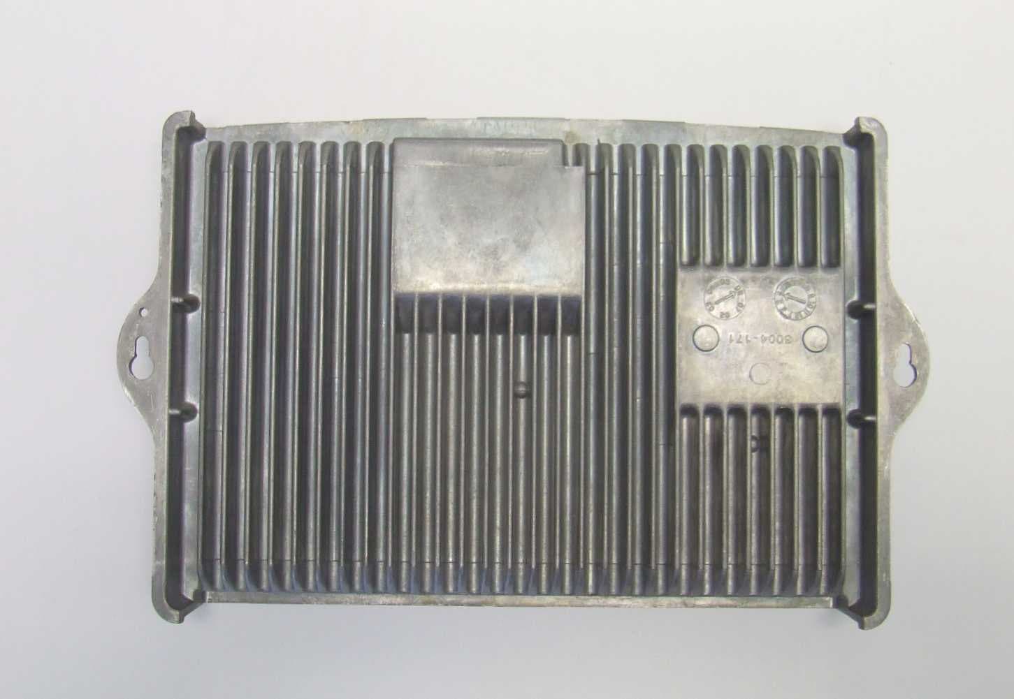
Click to zoom
Application Details
- Equipment Class
- MRD - Marine Radar
- Date of Grant
- Feb 06, 2008
- Application Purpose
- Original Equipment
- Date of Application
- Feb 06, 2008
- Equipment Note
- Light Marine Navigational Radar
- Frequency Range
- 9300.00000000 - 9500.00000000
- Company
- Flir Belgium BVBA
- Country
- Belgium
Documents & Files
Document Text
Text extracted from the exhibit documents filed with the FCC. Open a document above to read the original.
Users Manual
Digital Radar Installation Manual Document number: 87087-2 Date: December 2007 i Important Information ............................................................... 1 Intended use ................................................................................. 1 Raymarine Support ...................................................................... 3 System Overview ....................................................................... 7 1.1 Introduction ................................................................................... 7 System configuration .................................................................... 8 1.2 EMC installation guidelines ........................................................... 9 Connections to other equipment ................................................. 10 1.3 Unpacking and inspecting the components ................................ 11 What‘s in the box? .......................................................................11 What tools do I need? ..................................................................11 1.4 Selecting the digital radar unit site ............................................... 12 Digital radar dimensions ............................................................. 12 1.5 Mounting Surfaces ...................................................................... 15 Sailboats ..................................................................................... 15 Power Boats ............................................................................... 15 1.6 Setting the radiation plane ........................................................... 16 1.7 Cable requirements ..................................................................... 17 Digital Radar cable ..................................................................... 17 1.8 Power requirements .................................................................... 20 Voltage Converter Module (VCM100) ......................................... 21 1.9 Grounding the digital radar system .............................................. 23 1.10 Circuit breaker and fuse ratings ................................................. 24 Installing the Digital Radar Components ................................. 25 2.1 Digital radar ................................................................................. 25 2.2 Installing the VCM 100 ................................................................ 26 2.3 Securing the pedestal to the mounting platform .......................... 27 2.4 Removing the lifting eyes ............................................................ 31 2.5 Fitting the open array to the pedestal .......................................... 31 2.6 System Connections ................................................................... 34 Connecting the digital radar cable .............................................. 34 Digital Radar Connections .......................................................... 35 Data Connections ....................................................................... 35 Power Connections .................................................................... 35 Maintenance and Troubleshooting .......................................... 37 3.1 EMC Conformance ..................................................................... 37 3.2 System Checks ........................................................................... 37 3.3 Set up, alignment and timing checks ........................................... 38 Switch on and initial set up .......................................................... 38 Checking transmission ............................................................... 38 Bearing alignment ....................................................................... 38 Display timing adjustment ........................................................... 38 ii Parking alignment ....................................................................... 39 3.4 Maintenance ............................................................................... 40 Routine Checks .......................................................................... 40 Servicing and Safety ................................................................... 41 3.5 Problem Solving ......................................................................... 42 VCM100 status LED sequence’s ................................................ 43 1 Important Information Digital Radar Owners Handbook June 2007 Intended use This product is a radar scanner intended for use within a naviga- tional radar system. The intended application is for leisure marine boats and work boats not covered by IMO/SOLAS carriage requirements. Safety Notices WARNING: Electrical safety Ensure you have the power supply switched and locked off before you start installing/servicing this product. WARNING: Navigational safety Although we have designed this product to be accurate and reliable, many factors can affect its performance. Therefore, it should serve only as an aid to navigation and should never replace commonsense and navigational judgement. Always maintain a permanent watch so you can respond to situations as they develop. CAUTION: Before installing the Digital radar system, check that individual components are the correct voltage for your boat’s supply. As correct performance is critical for safety, we STRONGLY RECOMMEND that an Authorized Raymarine Service Representative fits this product. You will only receive full warranty benefits if you can show that an Authorized Raymarine Service Representative has installed or commissioned this product. This radar equipment must be installed, commissioned and operated in accordance with the Raymarine instructions provided. Failure to do so could result in personal injury, damage to your boat and/or poor product performance. In particular 1.High Voltage. The scanner unit contains high voltages. Adjust- ments require specialized service…
Text truncated - open the document above for the full version.
Cover Letter(s)
Raymarine PLC. Registered in England Company No. 04578449 Registered office. Anchorage Park, PO3 5TD T_04-401_Letter_Head.doc Raymarine plc Anchorage Park Portsmouth Hampshire PO3 5TD England +44 (0)23 9269 3611 +44 (0)23 9269 4642 (fax) www.raymarine.com Telecommunication Certification Body BABT Balfour House Churchfield Road Walton on Thames Surrey KT12 2TD Wednesday, 30 January 2008 Attention: Mr Alan Binks Dear Sir, Application for Grant of FCC Equipment Authorization Please find enclosed a CD ROM that contains the Application Forms and Exhibits from Raymarine for our new 12kW Digital Open Array Radar Scanner. The design is similar to the 4kW Digital Open Array Radar that BABT approved in September 2007. The differences are new Mod/PSU board, new magnetron and only a super high definition (SHD) variant. The FCC ID for this product is PJ5-DP12KW. Under normal circumstances Raymarine Open Array Radars are available with either 4ft or 6ft antennas, this application is for the 4ft antenna only and a application for 6ft will follow at a later date. There is a separate power module, which converts the vessels 12 or 24V dc supply to the 42V dc needed by the scanner. Both models are intended to operate with our E-Series or G-series networked multifunction display units. These displays do not form part of this application for Equipment Authorization, though information explaining connection and operation is included. The hardware and software is the subject of patent applications and we therefore request maximum confidentiality in all matters relating to this application. Part numbers for the Voltage Conversion Module and for the radar scanners with and without an open array antenna are given below: Raymarine 12kW SHD Digital Open Array Scanner ...................................................... E52069 Raymarine 12kW SHD Digital Open Array Scanner with 48" Antenna.................. RA1048HD Raymarine Voltage Conversion Module VCM100.......................................................... E52091 Raymarine PLC. Registered in England Company No. 04578449 Registered office. Anchorage Park, PO3 5TD T_04-401_Letter_Head.doc The information on the CD ROM has been organized as Exhibits containing: ! Circuits and Interconnections ! External Photographs ! BABT 731 Application Form ! Internal Photographs ! Label Details ! Parts List ! RF Exposure Statement ! Test Reports, which include Test Setup Photographs ! Manuals ! Technical Description including Block Diagram ! Tune-Up Statement ! Request for Confidentiality ! Application Letter (this letter) Please note that these applications are made under FRN 0013-3487-27. I believe the information provided should meet your requirements, but if you need any further information or clarification, please do not hesitate to contact myself or Peter Bowen Yours Faithfully Andrew Little BEng (Hons), MIEE, CEng Senior Compliance Engineer
Cover Letter(s)
Raymarine Limited Robinson Way Anchorage Park Portsmouth Hampshire PO3 5TD England 023 9269 3611 023 9269 4642 (Fax) www.raymarine.com Telecommunication Certification Body BABT Balfour House Churchfield Road Walton on Thames Surrey KT12 2TD 22 nd January 2008 Certification Application Confidentiality Request regarding application for certification of the following FCC Identifiers: • FCC ID PJ5-DP12KW (12kW Pedestal SHD Digital Radar Scanner) Pursuant to Sections 0.457 and 0.459 of the Commission's Rules, we hereby request confidential treatment of information accompanying these applications as outlined below: • Schematics • Block Diagrams • Parts Lists • Technical Description The above materials contain trade secrets and proprietary information not customarily released to the public. The public disclosure of these materials may be harmful to the applicant and provide unjustified benefits to its competitors. The applicant understands that pursuant to Section 0.457 of the Rules, disclosure of these applications and all accompanying documentation will not be made before the date of the Grant for these applications. Yours faithfully, Andrew Little Senior Compliance Engineer, Raymarine Limited
Cover Letter(s)
Raymarine UK Limited. Registered in England. Company No. 04578449 Registered Office: Quay point, Portsmouth PO6 3TD Raymarine Limited Quay Point Portsmouth Hampshire PO6 3TD England 023 9269 3611 023 9269 4642 (Fax) www.raymarine.com Federal Communications Commission Authorization & Evaluation Division I hereby declare that the 12kW Pedestal SHD Digital radar (E52082) complies with the following FCC regulations: • Part 80.205 • Part 80.209(b) • Part 80.211(f) • Part 80.213(g) • Part 80.215(a) • Part 80.217 I further declare that all measurements made in connection with this Application for Grant of FCC Equipment Authorization were carried out under my direct supervision and control by competent engineering staff, and that I have examined and verified the data contained in the accompanying Test Report. Sincerely, Andrew G Little, BEng (Hons), MIET, CEng. Senior Compliance Engineer Raymarine Limited Tel: +44(0)2392 693611 ext 1011/1619 [email protected] - 2 - Raymarine UK Limited. Registered in England. Company No. 04578449 Registered Office: Quay Point, Portsmouth, PO6 3TD Rev. 13/03/06
External Photos
NGS 4kW and 12kW Digital Open Array Radar Scanners External Photographs INDEX Page No. Description 3 Pedestal with 72" Antenna and 15m cable (4kW only) 4 Pedestal with 48" Antenna and 15m cable 5 Pedestal with Antenna and cable rem oved 6 Pedestal - view from rear 7 Pedestal - view from front 8 Pedestal - view from right-hand side 9 Pedestal - view from left-hand side 10 Pedestal - view from underside Page 2 of 10 NGS 4kW Digital Open Array Radar Scanner with 72" Antenna and 15m power/ethernet cable (not currently available for 12kW Exterior View 1 Page 3 of 10 NGS 4kW Digital Open Array Radar Scanner with 48" Antenna and 15m power/ethernet cable Exterior View 2 Page 4 of 10 NGS 4kW Digital Open Array Radar Scanner with Antenna and power/ethernet cable removed Exterior View 3 Page 5 of 10
External Photos
NGS Digital Open Arrays - VCM100 Voltage Converter Module External Photographs INDEX Page No. Description 3 VCM100 front view 4 VCM100 underside vi ew 5 VCM100 right-hand s ide view 6 VCM100 top view 7 VCM100 rear view (h eatsink) Page 2 of 7 VCM100 - front Exterior View 1 Page 3 of 7 VCM100 - underside Exterior View 2 Page 4 of 7 VCM100 - righthand side Exterior View 3 Page 5 of 7 VCM100 - top Exterior View 4 Page 6 of 7 VCM100 - rear (heatsink ) Exterior View 5 Page 7 of 7
External Photos
NGS 4kW Digital Open Array Radar Scanner - rear view showing cable connector and power switch Exterior View 4 Page 6 of 10 NGS 4kW Digital Open Array Radar Scanner - front view Exterior View 5 Page 7 of 10 NGS 4kW Digital Open Array Radar Scanner - right-hand side view Exterior View 6 Page 8 of 10 NGS 4kW Digital Open Array Radar Scanner - left-hand side view Exterior View 7 Page 9 of 10 NGS 4kW Digital Open Array Radar Scanner - underside of lower casting Exterior view 8 Page 10 of 10
Internal Photos
NGS 12kW Digital Open Array Radar Scanner Internal Photographs INDEX Page No. Description 3 Scanner opened for servicing - left-hand view 4 Scanner opened for servicing - right-hand view 5 Scanner opened for servicing - rear view 6 Scanner opened for servicing - core module removed 7 Motor/gearbox assembly and rotating joint 8 Radar core assembly - top view 9 Radar core assembly - top view - LNC cover removed 10 Radar core assembly - top view - LNC removed 11 LNC PCB module top (component) side with screening can removed 12 LNC PCB module underside 13 Radar core assembly - lower view 14 Modulator/PSU PCB - lower view 15 Radar core assembly - lower view - Modulator/PSU PCB removed 16 Modulator/PSU PCB - top (component side) view 17 Radar core assembly - lower view - IF cover removed 18 Radar core assembly - lower view - IF PCB Assembly removed 19 I.F. PCB Assembly top side 20 I.F. PCB Assembly underside Page 2 of 20 NGS 12kW Digital Open Array Radar Scanner - left-hand view - opened to service position Interior view 1 Page 3 of 20 NGS 12kW Digital Open Array Radar Scanner - right-hand view - opened to service position Interior view 2 Page 4 of 20 NGS 12kW Digital Open Array Radar Scanner - rear view - opened to service position Interior view 3 Page 5 of 20 NGS 12kW Digital Open Array Radar Scanner - interior view with radar core removed. Interior view 4 Page 6 of 20 NGS 12kW Digital Open Array Radar Scanner - view of motor/gearbox assembly and rotating joint. Interior view 5 Page 7 of 20
Internal Photos
NGS Digital Open Arrays - VCM100 Voltage Converter Module Internal Photographs INDEX Page No. Description 3 VCM100 - connector cover removed 4 VCM100 - front cove r removed 5 VCM100 - pcb remove d 6 VCM100 - pcb front view 7 VCM100 - pcb rear v iew Page 2 of 7 VCM100 - with connection cover removed Interior View 1 Page 3 of 7 VCM100 - with front cover and connector cover removed Interior View 2 Page 4 of 7 VCM100 - with pcb removed - heatsink casting Interior View 3 Page 5 of 7 VCM100 - pcb, component (front) side Interior View 4 Page 6 of 7 VCM100 - pcb, rear side Interior View 5 Page 7 of 7
Internal Photos
NGS 12kW Digital Open Array Radar Scanner - core module top view showing magnetron, circulator, cooling fan and fixed/rotary joint coupling. Interior view 6 Page 8 of 20 NGS 12kW Digital Open Array Radar Scanner - core module top view with cover removed to show LNC assembly. Interior view 7 Page 9 of 20 NGS 12kW Digital Open Array Radar Scanner - core module top view with LNC assembly removed. Interior view 8 Page 10 of 20 NGS 12kW Digital Open Array Radar Scanner - LNC assembly with screening can removed. Interior view 9 Page 11 of 20 NGS 12kW Digital Open Array Radar Scanner - LNC assembly underside. Interior view 10
Internal Photos
NGS 12kW Digital Open Array Radar Scanner - core module bottom view with magnetron and cooling fan connected. Interior view 11 Page 13 of 20 NGS 12kW Digital Open Array Radar Scanner - core module bottom view with cover removed to show underside of modulator/psu pcb - magnetron and cooling fan disconnected. Interior view 12 Page 14 of 20 NGS 12kW Digital Open Array Radar Scanner - core module bottom view with modulator/psu pcb removed to show IF assembly screening cover. Interior view 13 Page 15 of 20 NGS 12kW Digital Open Array Radar Scanner - modulator/psu pcb top view. Interior view 14 Page 16 of 20 NGS 12kW Digital Open Array Radar Scanner - core module bottom view with modulator/psu pcb and IF assembly cover removed. Interior view 15 Page 17 of 20
Internal Photos
NGS 12kW Digital Open Array Radar Scanner - core module bottom view with modulator/psu pcb and IF assembly removed. Interior view 16 Page 18 of 20 NGS 12kW Digital Open Array Radar Scanner - IF pcb assembly, top view Interior view 17 Page 19 of 20 NGS 12kW Digital Open Array Radar Scanner - IF pcb assembly, bottom view Interior view 18 Page 20 of 20
Parts List/Tune Up Info
Raymarine Limited. Registered in England. Company No. 1177969 Registered Office: Anchorage Park, Portsmouth PO3 5TD Raymarine Limited 12kW Pedestal – SHD Digital scanners FCC ID: PJ5-DP12KW Tune-up Procedures There are no Tune-up Procedures associated with the 12kW Pedestal Scanner (PJ5- DP12KW). Note: For Parts List information refer to the Schematic exhibits.
Test Report
TEST REPORT EMC DEPARTMENT RAYMARINE UK LTD Test of: Raymarine UK Ltd. 12kW Open Array Digital Radar To: FCC Part 80: 2007 and FCC Part 2: 2007 (Leisure Marine Radar Equipment) Test Report Serial No. 649/1080 Checked By: Mike Thompson EMC Engineer Approved By: Peter Bowen Compliance Manager Tested By: Michael Howes Author: Michael Howes EMC Engineer Issue Date: 25 th January, 2008 Test Dates: 3 rd January to 17 th January 2008 RAYMARINE LTD. TEST REPORT EMC Department No. 649/1080 Page 2 of 52 Test of: Raymarine Ltd. Issue Date: 25th January, 2008 12kW Open Array Digital Radar FCC Part 80: 2007 and FCC Part 2: 2007 __________________________________________________________________________ Table of Contents 1 Client Information .............................................................................................................. 3 2 Equipment Under Test (EUT) ........................................................................................... 4 2.1 Identification of Equipment Under Test (EUT) ......................................................... 4 2.2 Description of EUT ................................................................................................... 4 2.3 Modifications incorporated in EUT ........................................................................... 4 2.4 Additional information related to Testing.................................................................. 5 2.5 Support Equipment................................................................................................... 5 3 Test Specification, Methods and Procedures ................................................................... 6 3.1 Test Specification ..................................................................................................... 6 3.2 Methods and Procedures ......................................................................................... 6 3.3 Definition of Measurement Equipment ..................................................................... 6 4 Deviations from the Test Specification ............................................................................. 7 5 Operation of the EUT during Testing ................................................................................ 8 5.1 Operating Conditions................................................................................................ 8 5.2 Operating Modes...................................................................................................... 8 5.3 Configuration and peripherals .................................................................................. 8 6 Summary of Test Results.................................................................................................. 9 6.1 Summary of Tests .................................................................................................... 9 6.1.1 Radiated Spurious Emissions .............................................................................. 9 6.1.2 Conducted Spurious Emissions ........................................................................... 9 6.1.3 RF Power Output ................................................................................................. 9 6.1.4 Variation of Frequency with Voltage .................................................................. 10 6.1.5 Variation of Frequency with Temperature.......................................................... 10 6.1.6 Occupied Bandwidth .......................................................................................... 10 6.1.7 Transmitter Frequency Tolerance...................................................................... 10 6.1.8 Suppression of Interference Aboard Ships ........................................................ 11 6.2 Location of Tests .................................................................................................... 11 7 Measurements, Examinations and Derived Results ....................................................... 12 7.1 General Comments ................................................................................................ 12 7.2 Field Strength Measurements ................................................................................ 12 7.2.1 Magnetic Field Measurements: Frequency Range 9 kHz to 30 MHz ................ 12 7.2.2 Electric Field Measurements: Frequency Range 30 MHz to 2000 MHz............ 12 7.2.3 Electric Field Measurements: Frequency Range: 2GHz to 40GHz ................... 12 7.3 Conducted Emissions............................................................................................. 13 7.3.1 Peak Detector measurements on RF port ......................................................... 13 7.4 Peak Power ............................................................................................................ 13 7.5 Pulse Width ............................................................................................................ 14 7.6 Pulse Repetition Frequency ................................................................................... 14 7.7 Average Power ....................................................................................................... 15 7.8 Variation of frequency with input voltage ............................................................... 15 7.9 Variation of frequency with temperature ................................................................ 16 7.10 Occupied Bandwidth .............................................................................................. 17 7.11 Transmitter Frequency Tolerance .......................................................................... 18 7.11.1 Specification: 80.209(b) ................................................................................. 18 7.11.2 Calculation ..................................................................................................... 18 8 Measurement Uncertainty....................…
Text truncated - open the document above for the full version.
Contact Information
Applicant
Roy C Ediss(Approvals Engineer)
Technical Contact
Raymarine UK LtdAndy Little
[email protected]+44 2392693611
Robinson Way · Portsmouth · United Kingdom
Non-Technical Contact
Raymarine UK LtdAndy Little
[email protected]+44 2392693611
Test Firm
Raymarine UK LimitedAndy Little
Technical Specifications
| # | Rule Parts | Frequency Range | Power Output | Emission |
|---|---|---|---|---|
| 1 | 80 | 9.30 GHz - 9.50 GHz | 12000 W | 40M3P0N |
Other Applications from Flir Belgium BVBA
PJ5-AX2PLUS
Apr 20, 2026Fish finder with Bluetooth and 2.4GHz Wi-Fi
Equipment Class
DSS - Part 15 Spread Spectrum Transmitter
PJ5-RAY901
Jun 08, 2022RAY91 VHF Black Box with AIS Rx
Equipment Class
TNB - Licensed Non-Broadcast Station Transmitter
PJ5-953LPSSR
Jun 28, 2021Non-SOLAS solid state marine radar
Equipment Class
MRD - Marine Radar
PJ5-953MPSSR
Jun 28, 2021Non-SOLAS solid state marine radar
Equipment Class
MRD - Marine Radar
PJ5-RAY4GHUB
Apr 18, 2021YachtSense Link Marine Cloud Router
Equipment Class
NII - Unlicensed National Information Infrastructure TX