PJ5H6LLTH6 Lifeline Transmitter Tag
Flir Belgium BVBA
Click to zoom
Application Details
- Equipment Class
- DXX - Part 15 Low Power Communication Device Transmitter
- Date of Grant
- Sep 14, 2005
- Application Purpose
- Original Equipment
- Date of Application
- Sep 14, 2005
- Equipment Note
- H6 Lifeline Transmitter Tag
- Frequency Range
- 914.28000000 - 914.69900000
- Company
- Flir Belgium BVBA
- Country
- Belgium
Documents & Files
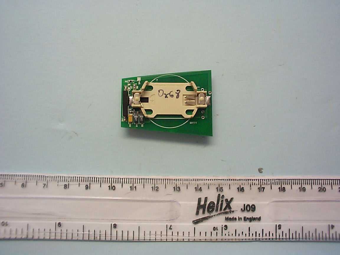
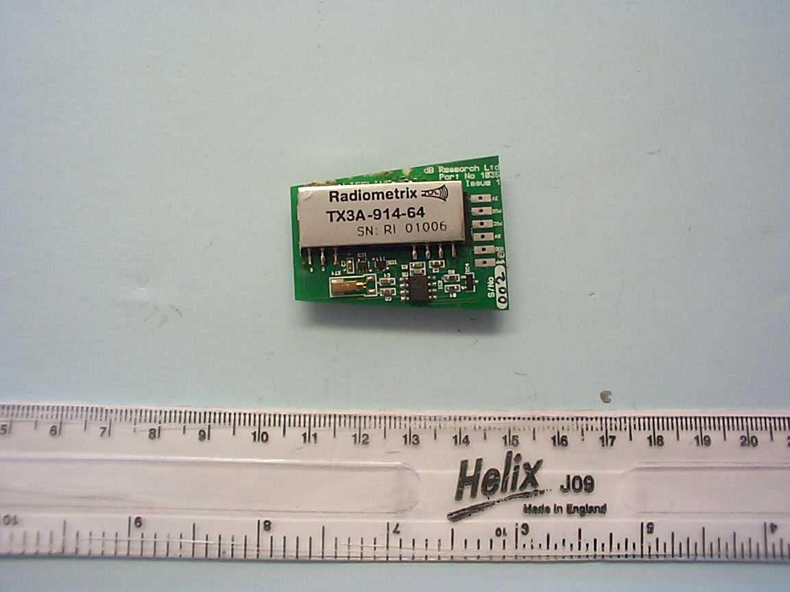
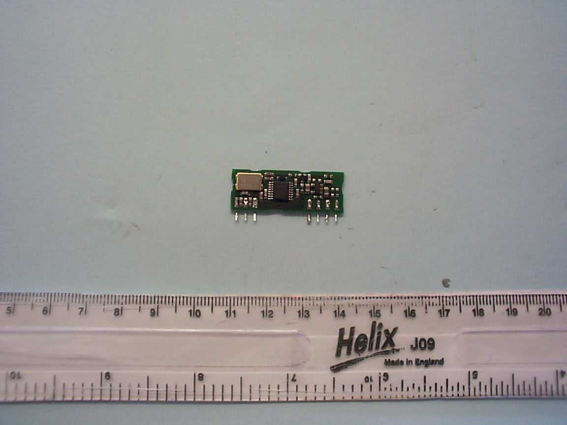
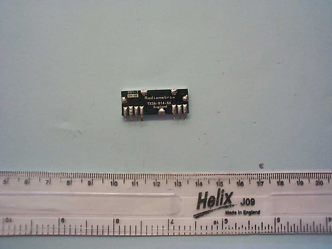
Document Text
Text extracted from the exhibit documents filed with the FCC. Open a document above to read the original.
Users Manual
Using Lifeline99 Using Lifeline WARNING: Lifeline Lifeline is an aid to crew safety only. It should not be relied upon as the boat’s main crew safety system. It is the responsibility of the Captain and all crew members to ensure that specific safety instructions and procedures are in place and obeyed in accordance with local safety requirements. Introduction Crew safety is paramount. Lifeline is a positive reporting system that is permanently ‘on’. Each crew member is given an activated radio transmitter in the form of a key tag, which will stop working and raise an audible alarm if they go overboard. FCC Notice This device complies with Part 15 of the FCC Rules. operation is subject to the following conditions: 1. This device may not cause harmful interference. 2. This device must accept any interference received, including interference that may cause undesied operation. Changes or modifications to this equipment, not expressly apprved by Raymarine Inc., could violate compliance with FC C rules and void the operator’s authority to operate the equipment. The receiver The Lifeline receiver is located adjacent to the display units at the main helm position and consists of a sculptured face-plate into which a key-tag can be placed. When a key-tag is placed in the face-plate it can be either activated or de- activated as required. 81238_2.book Page 99 Friday, August 19, 2005 11:18 AM 100Raymarine H6 - Owner’s Manual The transmitter The Lifeline transmitter consists of a key tag which can be attached to a crew member’s clothing by the built-in clip or attached to a lanyard for additional security. The tags are numbered from 1 through 8 and need to be re-activated every 24 hours to ensure continuous coverage. If a crew member leaves the boat intentionally, their tag must be de-activated to prevent a false alarm being initiated. Lifeline databox The Lifeline databox shows the status of all Lifeline tags. Activated tags are shown in green, inactive tags are shown in grey.Moving the cursor over a tag indicator will cause a yellow box to appear around it. Information for that tag is then displayed in the databox. D7318_1 D7580_1 81238_2.book Page 100 Friday, August 19, 2005 11:18 AM Using Lifeline101 Activating the tags To activate a Lifeline tag: 1. Select and open the Lifeline data box. 2. Place the tag that to be registered on the Lifeline receiver. The corresponding tag number will be highlighted in the on-screen data box by a yellow border. 3. Click Activate Tag. The data box will now show that the tag has been activated and display the time that the activation will expire. The tag should be re-activated using steps 1 through 3 before the expiry time. When a crew member is leaving the boat for a legitimate reason, their Lifeline tag should be de-activated to prevent a false alarm situation. To de-activate a Lifeline tag: 1. Select and open the Lifeline data box. 2. Place the tag to be de-activated on the Lifeline receiver. The corresponding tag number will be highlighted in the on-screen data box by a yellow border. 3. Click Deactivate Tag. The data box will now show that the tag is not regis- tered. It is now safe for the crew member to leave the boat without causing a false alarm. 81238_2.book Page 101 Friday, August 19, 2005 11:18 AM 102Raymarine H6 - Owner’s Manual Lifeline alarm The Lifeline receiver is constantly sampling the signals from all registered tags. If it does not receive a reply from a tag, an alarm is automatically raised. This will normally be within 10 seconds of the tag disappearing. In the event of an alarm, the Lifeline data box will automatically expand onto the left hand screen. It will show which tag has alarmed and give details of time position, and the boat’s speed at the time of the alarm. A Man Overboard marker will also be placed on the chart screen. D7581_1 81238_2.book Page 102 Friday, August 19, 2005 11:18 AM Using Lifeline103 Lifeline reset There are two occasions when it may be necessary to reset the Lifeline system to ensure correct system operation, these are: • If a tag has been lost. You will be unable to deactivate the tag and clear it from the system. • If H6 is switched off and tag expiry time occurs. When H6 is switched back on the expired tag will cause a Man Overboard alert to be displayed. To carry out a Lifeline reset: 1. Click Reset Lifeline. An action box will appear asking if you are sure you want to reset the system. 2. Click Ye s. The Scanning for tags action box is displayed and a ten second countdown starts. 3. When the scan has completed a message is displayed showing all tags detected and asking if you wish to register them. 4. Click Ye s to register tags. 5. Click No to clear and reset the Lifeline system. D7525_1 81238_2.book Page 103 Friday, August 19, 2005 11:18 AM 104Raymarine H6 - Owner’s Manual 81238_2.book Page 104 Friday, August 19, 2005 11:18 AM
Operational Description
H6 Lifeline USA Overview Lifeline is an automatic Man Overboard (MOB) system that uses positive reporting from personnel lifeline tag transmitters operating on 915.5MHz. It is intended for use as part on a H6 navigation system. The Lifeline system consists of upto 4 receivers and upto sixteen lifeline transmitters. A tag transmitter is issued to all personnel on the boat. The receiver listens for tag ID reports from each of the transmitters and an alarm is raised if none from a particular tag are received in about 10 seconds. The loss of the tag signal is indicated on H6 electronic chart on the H6 monitors at the helm position and the time and position of the craft is noted and displayed. Inputs from the boat’s GPS provide position and time data. The boat speed is also noted and displayed. Lifeline Transmitter The lifeline transmitter (known as the lifeline tag) is a small keyfob device worn by all personnel on the boat (vessel). Activation of the tag is performed by the H6 Navigation system. Once activated, the tag will transmit for a 24-hour period or until deactivated. The H6 navigation system will issue a warning if a tags’ 24 hour period is nearing expiry. The user must then re-activate the tag. Deactivation is also performed through the H6 navigation system. Each tag uses a Radiometrix RX3A FM radio module operating at 914.5MHz. Standard 2 level digital data at 9600bps is used to modulate the FM carrier. The tags message consists of a 2 byte preamble followed by a 10 bit message. The data is Manchester encoded resulting in a message length of 52 bits. This results in a transmission period of 5.42mS, a duty cycle of approximately 0.5%. The message length has been kept to an absolute minimum so that battery life is maximised and duty cycle is minimised. The data preamble allows the lifeline receiver to synchronise with the incoming message. The data payload consists of the tags identification (tag ID) number and status bits. The tag ID is used by the receiver as an indication that the tag is still onboard the vessel. Status bits are included in the message sent to the receiver, these indicate the tags current status, for example - low battery alarm. The tags firmware implements a pseudo-random sequence, which ensures that each tag, transmits 10 times in any 10-second time slot. Each tags pseudo-random number generator is initialised with a different ‘seed’, which minimises individual message collisions between the individual tag transmitters. Battery voltage is measured and if below a 2.5V threshold then status bits are modified. The lifeline receiver decodes these status bits. An alarm will be generated by the H6 Navigation system if the tags battery needs replacing. Specification Transmitter Supply Voltage : 3V (Lithium 2430 Coin cell) Transmitter ERP : 1mW External Interface : None Antennae : PCB track Connections : None Transmitter Duty Cycle : 0.5% Lifeline Receiver The lifeline receiver is responsible for - decoding the messages from the tag transmitters - activating and deactivating lifeline tags - communicating its status and the tags status to the H6 Navigation system The receiver utilises two Radiometrix TX3A FM radio receivers connected to two Microchip PIC microcontrollers. Each of these micrcontrollers (known as the slave controllers) is solely responsible for decoding the messages received from the digital data outputs of each of the radio modules. Communication with the H6 Navigation system is performed by another Microchip PIC microcontroller (known as the master controller). These microcontrollers are connected together using an IIC (Inter Integrated Circuit I2C) bus. Activation and Deactivation of the lifeline tags is controlled by the H6 Navigation system. Communication with the H6 system achieved using an RS232 link operating at 9600bps. The tag activation sequence is initiated by the H6 Navigation system. The lifeline receiver will respond by driving the electromagnet with an activation signal. Note that the tag transmitter must be placed in the recess of the lifeline faceplate. The tag will decode this signal and commence transmission. The tag will continue to transmit until deactivated or its 24-hour activation period expires. Deactivation follows a similar sequence. As mentioned earlier, each slave microcontroller is responsible for decoding messages received by its radio receiver module. The antennae’s for these receiver modules are connected in opposite orientation, at strategic positions on the vessel. Sampling of the digital output of the radio modules is performed to synchronise the receiver with the incoming message. Once the message has been successfully decoded, the slave indicates to the master controller that it has received a message. The master will then read this message over the IIC bus. The master controller keeps track of the status of the lifeline system (for example message frequency, number and tag ID’s of active tags, any alarm conditions). The master controller transfers this information to the H6 navigation system on request. The H6 navigation system uses this information to update its displays. Specification Receiver Supply Voltage : 9-35V DC (12V when connected to H6 NAV System) Power Consumption : 0.6W(min), 12W (max) External Interface : RS232 (9600 baud, 8 data, no parity & 1 stop bit) Connections : 5 way XLR socket, 2 BNC jacks Antennae : 2 quarter wave dipoles
Operational Description
Radiometrix Ltd, TX3A & RX3 Data Sheet page 1 Features: Frequencies available as standard: 869.85MHz, 914.5MHz CE certified by independent Notified Body Verified to comply with Radio standard EN 300 220-3 by accredited Test Laboratory Verified to comply with EMC standard EN 301 489-3 by accredited Test Laboratory North American version conforms to FCC part 15.249 Data rates up to 64kbps Fully screened Available for operation in the 868-870MHz band in Europe and the 902–928MHz band in North America, both modules combine full screening with internal filtering to ensure EMC compliance by minimising spurious radiation and susceptibility. The TX3A & RX3 will suit one-to-one and multi-node wireless links in such applications as car and building security, EPOS and inventory tracking, remote industrial process monitoring and data networks. Because of their small size and low power requirements, both modules are ideal for use in portable, battery-powered applications such as hand-held terminals. Transmitter – TX3A Crystal-locked PLL, FM modulated at up to 64 kb/s Operation from 2.2V to 12V @ 7.5mA Built-in regulator for improved stability and supply noise rejection 1mW nominal RF output Enable facility Update of the original TX3 with enhanced performance Receiver – RX3 Single conversion FM superhet with SAW front end filter Operation from 2.7V to 12V @ 9.5mA Built-in regulator for improved stability and supply noise rejection 64kb/s, -98dBm sensitivity @ 1ppm BER RSSI output with 75dB range Enable facility Radiometrix Issue: 0150-1-2WW TX3A & RX3 3 September 2002 European versions: TX3A-869-64/RX3-869-64 USA versions: TX3A-914-64/RX3-914-64 The TX3A & RX3 are miniature UH F radio transmitter & receiver modules designed for PCB mounting. They allow the simple implementation of data links at speeds up to 64kbps and distances up to 30m in-building or 120m over open ground. TX3A Transmitter RX3 Receiver UHF FM Data Transmitter and Receiver Modules Radiometrix Ltd, TX3A & RX3 Data Sheet page 2 Functional description The TX3A transmitter module uses a frequency modulated crystal-locked PLL and operates between 2.2V and 12V at a current of 7.5mA nominal. At 3V supply it delivers nominally 0dBm (1mW) RF output. The SIL style TX3A measures 32 x 12 x 3.8 mm, excluding pins. The RX3 module is a single conversion FM superhet receiver capable of handling data rates of up to 64kb/s. It will operate from a supply of 2.7V to 12V and draws 9.5mA when receiving. The RX3 features a fast power-up time for effective duty cycle power saving and a signal strength (RSSI) output with 75dB of range. Full screening and a SAW front-end filter give good immunity to interference. The SIL style RX3 measures 48 x 17.5 x 4.5 mm, excluding pins. TX3A transmitter Fig 1 :TX3A block diagram Vcc (pin 5) +2.2V to +12V DC supply. Max ripple content 0.1V P-P . Decoupling is not generally required. 0V (pin 6) DC supply ground. Internally connected to pins 1 & 3 and module screen. TXD (pin 7) DC-coupled modulation input. Accepts serial digital data at 0V to 2.5V levels. See applications notes for suggested drive methods. Input is high impedance (>1MΩ). Pin description RF GND (pins 1&3) RF ground, internally connected to the module screen and pin 6 (0V). These pins should be directly connected to the RF return path - e.g. coax braid, main PCB ground plane etc. RF OUT (pin 2) 50Ω RF output to the antenna. Internally DC-isolated. See antenna section of apps notes for details of suitable antennas. En (pin 4) Tx enable. <0.15V shuts down module (current <1μA). >1.7V enables the transmitter. Impedance ~1MΩ. Observe slew rate requirements (see apps notes). 868/915 MHz band pass filter buffer 2 RF out 3 RF gnd Loop Filter 35kHz LPF ref osc φ 7 TXD 1 supply regulator 4 En 5 2.2 -- 12V ÷ 64 V C O 6 0V 3.8 mm 32 mm 12.0 mm 12.5 mm PCB level Radiometrix TX3 7 holes, 0.7 mm dia, pin spacing 2.54 mm Fig2: TX3A physical dimensions 15.24 mm 1 23 4567 1 = RF GND 2 = RF OUT 3 = RF GND 4 = En 6 = 0V 7 = TXD 5 = Vcc Radiometrix Ltd, TX3A & RX3 Data Sheet page 3 RX3 receiver VCO 35kHz 8 AF out 9 RXD 6 0V 4 En 1st Mixer 2, 3 RF gnd IF Amp Demod REF Φ 64 ÷ supply regulator 7 V cc 5 RSSI 10.7MHz 1 RF in Preamp. 868/915 MHz Band Pass Filter data slicer 10k Fig.3: RX3 block diagram En (pin 4) Rx enable. <0.15V shuts down module (current <1μA). >1.7V enables the receiver. Impedance ~1MΩ. Observe Fig.4: RX3 physical dimensions slew rate requirements (see apps notes). RSSI (pin 5) Received signal strength indicator with >65dB range. See applications notes for typical characteristics. 0V (pin 6) DC supply ground. Internally connected to pins 2 & 3 and module screen. Vcc (pin 7) +2.7V to +12V DC supply. Max ripple content 0.1V P-P . Decoupling is not generally required. AF out (pin 8) Buffered and filtered analogue output from the FM demodulator. Standing DC bias 1.3V approx. External load should be >50kΩ // <100pF. NOTE: AF waveform from this pin is inverted. RXD (pin 9) Digital output from the internal data slicer. The data is true data, i.e. as fed to the transmitter. Output is “open-collector” format with internal 10kΩ pull-up to Vcc (pin 7). Pin description RF IN (pin 1) 50Ω RF input from antenna. Internally DC-isolated. See antenna section of applications notes for suggested antennas and feeds. RF GND (pins 2 & 3) RF ground, internally connected to the module screen and pin 6 (0V). These pins should be connected to the RF return path - e.g. coax braid, main PCB ground plane etc. 9 holes of 0.7 mm dia. pin spacing 2.54mm 12 3 48 mm 17.5 mm 18.0 mm PCB level Radiometrix RX3 456798 25.4 mm 1 = RF IN 2 = RF GND 3 = RF GND 4 = En 5 = RSSI 6 = 0V 7 = Vcc 8 = AF out 9 = RXD 4.5 mm Radiometrix Ltd, TX3A & RX3 Data Sheet page 4 Absolute maximum ratings Exceeding the values given below may cause permanent damage to the module. Operating temperature -20°C to +70°C Storage temperature -40°C to +100°C TX3A Vcc (pin 5) -0.3V to +16V TXD (pin 7) ±7V En (pin 4) -0.3V to +Vcc V R…
Text truncated - open the document above for the full version.
Test Report
TRL COMPLIANCE SERVICES LTD EMC DIVISION M OSS VIEW NIPE LANE UP HOLLAND WEST LANCASHIRE WN8 9PY UNITED KINGDOM T ELEPHONE +44 (0)1695 556666 FAX +44 (0)1695 557077 E-MAIL [email protected] www.trlcompliance.com 0728 FS 21805 TEST REPORT NO: RU1179/6176 COPY NO: 2 ISSUE NO: 1 FCC ID: PJ5H6LLT REPORT ON THE CERTIFICATION TESTING OF A RAY MARINE INC H6 LIFELINE TRANSMITTER WITH RESPECT TO THE FCC RULES CFR 47, PART 15.249 January 2005 INTENTIONAL RADIATOR SPECIFICATION ON BEHALF OF dB RESEARCH LIMITED TEST DATE: 31 st March 2005 – 1 st April 2005 TESTED BY: D WINSTANLEY APPROVED BY: P GREEN EMC PRODUCT MANAGER DATE: 12 th September 2005 Distribution: Copy Nos: 1. dB RESEARCH LIMITED 2. FCC EVALUATION LABORATORIES 3. TRL EMC THIS DOCUMENT MAY BE REPRODUCED ONLY IN ITS ENTIRETY AND WITHOUT CHANGE RF335U iss03 RU1179/6176 Page 2 of 23 CONTENTS PAGE CERTIFICATE OF CONFORMITY & COMPLIANCE 3 APPLICANT’S SUMMARY 4 EQUIPMENT TEST CONDITIONS 5 TESTS REQUIRED 5 TEST RESULTS 6-9 ANNEX PHOTOGRAPHS A PHOTOGRAPH No. 1: Test setup PHOTOGRAPH No. 2: Transmitter front view PHOTOGRAPH No. 3: Transmitter rear view PHOTOGRAPH No. 4: Transmitter PCB track side PHOTOGRAPH No. 5: Transmitter PCB component side PHOTOGRAPH No. 6: RF Module component side PHOTOGRAPH No. 7: RF Module component side APPLICANT’S SUBMISSION OF DOCUMENTATION LIST B BAND OCCUPANCY PLOT C SCAN PLOT(s) D Notes: 1. Component failure during test YES NO [ ] [X] 2. If Yes, details of failure: 3. The facilities used for the testing of the product contain in this report are FCC Listed. 4. The contents of the attached applicants declarations and other supplied information are not covered by the scope of this laboratory’s UKAS or FCC accreditations’ and is provided in good faith. RF335U iss03 RU1179/6176 Page 3 of 23 CERTIFICATE OF CONFORMITY & COMPLIANCE FCC IDENTITY: PJ5H6LLT PURPOSE OF TEST: Certification TEST SPECIFICATION: FCC RULES CFR 47, Part 15.249 January 2005 TEST RESULT: Compliant to Specification EQUIPMENT UNDER TEST: H6 Lifeline Transmitter EQUIPMENT SERIAL No: Engineering Sample ITU: EMISSION CODE: 419KF1D EQUIPMENT TYPE: Personnel Location PRODUCT USE: Distress Signalling CARRIER EMISSION: 7852.35 μV/m @ 3m ANTENNA TYPE: Integral ALTERNATIVE ANTENNA: Not applicable FREQUENCY OF OPERATION: 914.45 MHz CHANNEL SPACING: Not applicable, Wideband NUMBER OF CHANNELS: Not applicable FREQUENCY GENERATION: SAW Resonator [ ] Crystal [ ] Synthesiser [X] MODULATION METHOD: Amplitude [ ] Digital [X] Angle [ ] POWER SOURCE(s): +3Vdc TEST DATE(s): 31 st March 2005 – 1 st April 2005 ORDER No(s): 0170/RH1 APPLICANT: dB Research Limited ADDRESS: Concept House 17 Merton Road Bootle Merseyside L20 3BG United Kingdom TESTED BY: D WINSTANLEY APPROVED BY: P GREEN EMC PRODUCT MANAGER RF335U iss03 RU1179/6176 Page 4 of 23 APPLICANT’S SUMMARY EQUIPMENT UNDER TEST (EUT): H6 Lifeline Transmitter EQUIPMENT TYPE: Personnel Location SERIAL NUMBER OF EUT: Engineering Sample PURPOSE OF TEST: Certification TEST SPECIFICATION(s): FCC RULES CFR 47, Part 15.249 January 2005 TEST RESULT: COMPLIANT Yes No [X] [ ] APPLICANT’S CATEGORY: MANUFACTURER IMPORTER DISTRIBUTOR TEST HOUSE AGENT [X] [ ] [ ] [ ] [ ] APPLICANT’S ORDER No(s): 0170/RH1 APPLICANT’S CONTACT PERSON(s): Mr E Runciman E-mail address: [email protected] APPLICANT: dB Research Limited ADDRESS: Concept House 17 Merton Road Bootle Merseyside L20 3BG United Kingdom TEL: +44 (0)151 330 0800 FAX: +44 (0)151 330 0808 MANUFACTURER: Raymarine UK Limited ADDRESS: 21 Manchester Street Merrimack New Hampshire United States 03054 TEL: +44 (0) 23 9269 3611 FAX: +44 (0) 23 9269 4642 EUT(s) COUNTRY OF ORIGIN: United Kingdom TEST LABORATORY: TRL EMC UKAS ACCREDITATION No: 0728 TEST DATE(s) 31 st March 2005 – 1 st April 2005 TEST REPORT No: RU1179/6176 RF335U iss03 RU1179/6176 Page 5 of 23 EQUIPMENT TEST / EXAMINATIONS REQUIRED 1. TEST/EXAMINATION RULE PART DETECTOR APPLICABILITY Intentional Emission Frequency: 15.249(a) Quasi Peak YES Intentional Emission Field Strength: 15.249(a) Quasi Peak YES Intentional Emission Band Occupancy: 15.215 Peak YES Intentional Emission ERP (mW): N/A - NO Spurious Emissions – Conducted: 15.207 - NO Spurious Emissions – Radiated <1000MHz: 15.209 Quasi Peak YES Spurious Emissions – Radiated >1000MHz: 15.209 15.249(a) Average YES Maximum Frequency of Search: 15.33 - YES Antenna Arrangements Integral: 15.203 - YES Antenna Arrangements External Connector: 15.204 - YES Restricted Bands 15.205 - YES Extrapolation Factor 15.31(f) - YES 2. Product Use: Distress signalling 3. Emission Designator: 419KF1D 4. Duty Cycle: <100 % 5. Transmitter bit or pulse rate and level: bps 6. Temperatures: Ambient (Tnom) 15 o C 7. Supply Voltages: Vnom +3Vdc Note: Vnom voltages are as stated above unless otherwise shown on the test report page Single channel [X] Two channel [ ] 8. Equipment Category: Multi-channel [ ] Narrowband [ ] Wideband [X] 9. Channel spacing: RF335U iss03 RU1179/6176 Page 6 of 23 TRANSMITTER TESTS TRANSMITTER SPURIOUS EMISSIONS – RADIATED – PART 15.209 & 15.249(a) Ambient temperature = 15 o C(<1GHz) 3m measurements <1GHz [X] Relative humidity = 44% (<1GHz), 0.3m measurements >1GHz [X] Conditions = Open Area Test Site (OATS) 3m extrapolated from 0.3m [X] Supply voltage = +3Vdc Channel number = 1 FREQ. (MHz) MEAS. Rx. (dBμV) CABLE LOSS (dB) ANT FACTOR FIELD STRENGTH (dBμV/m) EXTRAP. FACTOR (dB) FIELD STRENGTH (μV/m) LIMIT (μV/m) 1.705MHz - 30MHz Note 9 30MHz - 88MHz Note 9 88MHz - 216MHz Note 9 216MHz - 960MHz Note 9 960MHz - 1GHz Note 9 1GHz - 5GHz Note 9 1.705MHz to 30MHz 30μV/m @ 30m 30MHz to 88MHz 100μV/m @ 3m 88MHz to 216MHz 150μV/m @ 3m 216MHz to 960MHz 200μV/m @ 3m 960MHz to 1GHz 500μV/m @ 3m Limits 1GHz to 5GHz 500μV/m @ 3m Notes: 1 Results quoted are extrapolated as indicated 2 Emissions were searched to: (x) 1000MHz inclusive, as per Part 15.33a 3 Extrapolation factor 20dB from 0.3m to 3m, as per Part 15.31f 4 Measurements >1GHz @ 0.3m as per Part 15.31f(1) 5 Receiver detecto…
Text truncated - open the document above for the full version.
Test Setup Photos
RF335U iss03RU1179/6176Page 11 of 23 PHOTOGRAPH No. 1TEST SETUP
Contact Information
Applicant
Roy C Ediss(Approvals Engineer)
Technical Contact
dB Research LimitedErnie Runciman
[email protected]+44 151 330 0800
Concept House · Bootle, Merseyside · United Kingdom
Test Firm
TRL Compliance LtdJohn Charters
Technical Specifications
| # | Rule Parts | Frequency Range | Power Output |
|---|---|---|---|
| 1 | 15C | 914.28 MHz - 914.699 MHz | - |
Other Applications from Flir Belgium BVBA
PJ5-AX2PLUS
Apr 20, 2026Fish finder with Bluetooth and 2.4GHz Wi-Fi
Equipment Class
DSS - Part 15 Spread Spectrum Transmitter
PJ5-RAY901
Jun 08, 2022RAY91 VHF Black Box with AIS Rx
Equipment Class
TNB - Licensed Non-Broadcast Station Transmitter
PJ5-953LPSSR
Jun 28, 2021Non-SOLAS solid state marine radar
Equipment Class
MRD - Marine Radar
PJ5-953MPSSR
Jun 28, 2021Non-SOLAS solid state marine radar
Equipment Class
MRD - Marine Radar
PJ5-RAY4GHUB
Apr 18, 2021YachtSense Link Marine Cloud Router
Equipment Class
NII - Unlicensed National Information Infrastructure TX