PJ5RAY215Marine Transceiver
Flir Belgium BVBA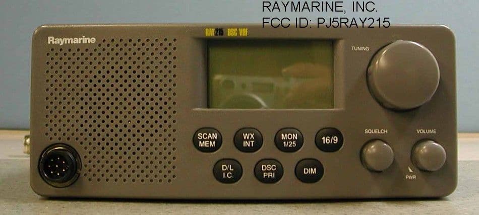
Click to zoom
Application Details
- Equipment Class
- TNB - Licensed Non-Broadcast Station Transmitter
- Date of Grant
- Nov 13, 2001
- Application Purpose
- Original Equipment
- Date of Application
- Sep 24, 2001
- Equipment Note
- Marine Transceiver
- Frequency Range
- 156.02500000 - 157.42500000
- Company
- Flir Belgium BVBA
- Country
- Belgium
Documents & Files
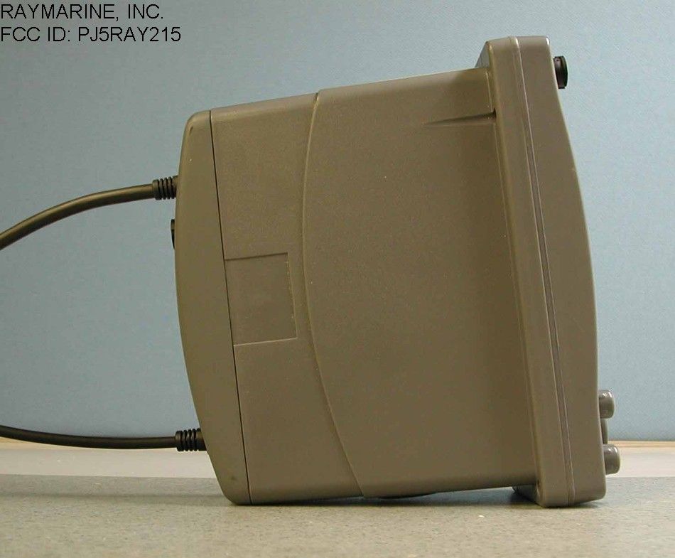
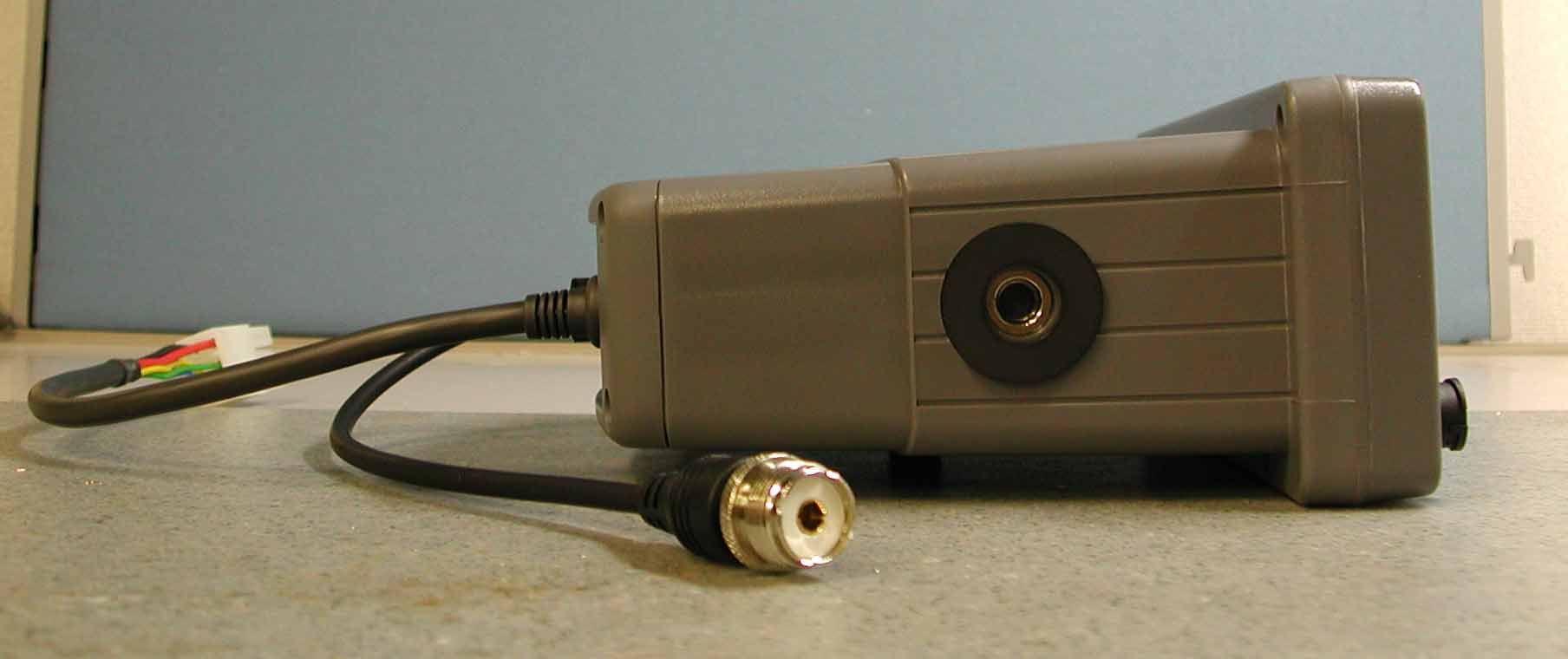

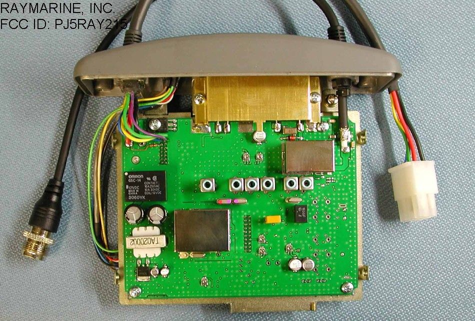
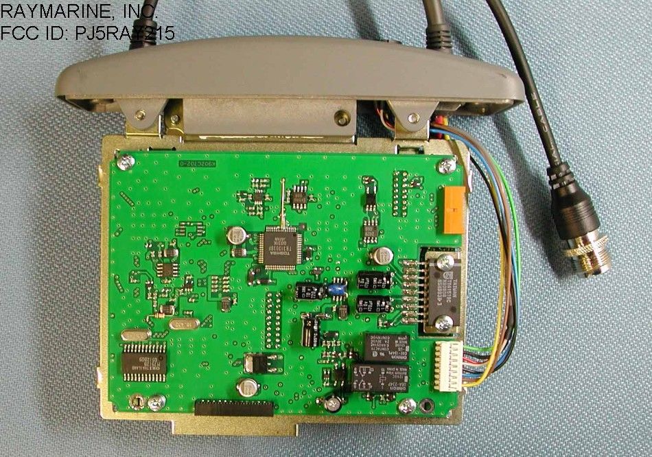
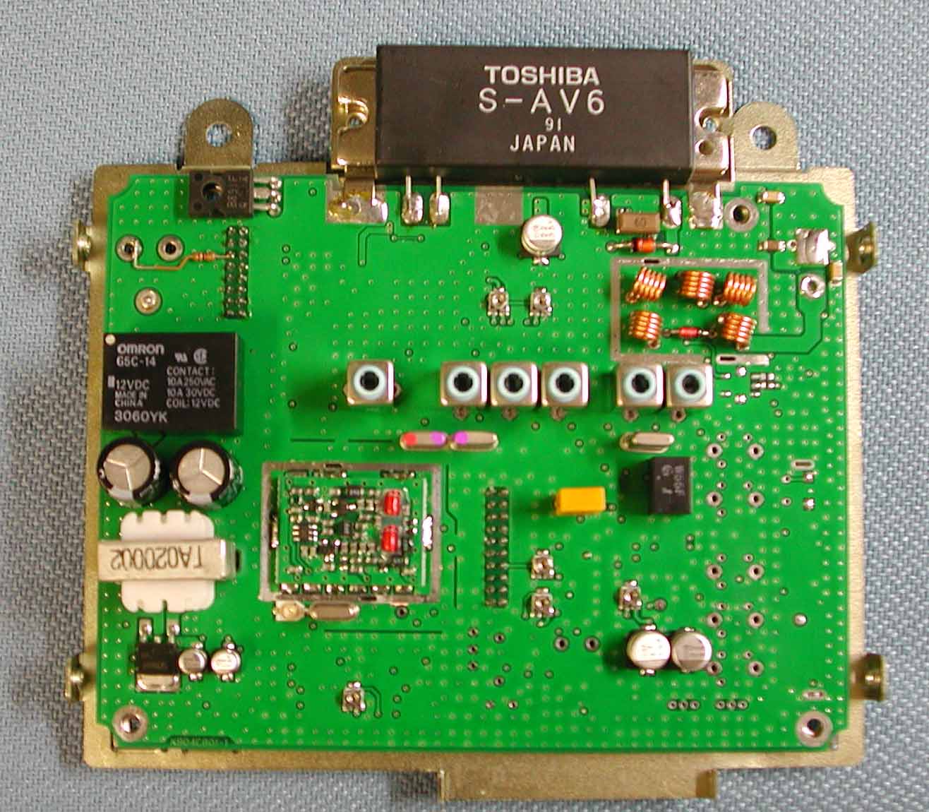
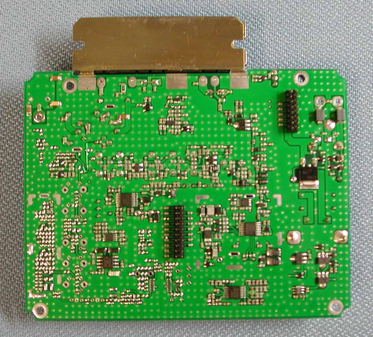
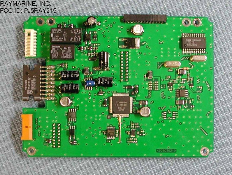
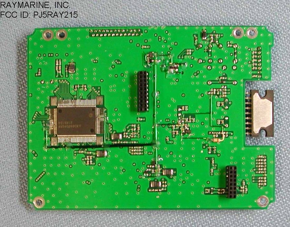
Document Text
Text extracted from the exhibit documents filed with the FCC. Open a document above to read the original.
Users Manual
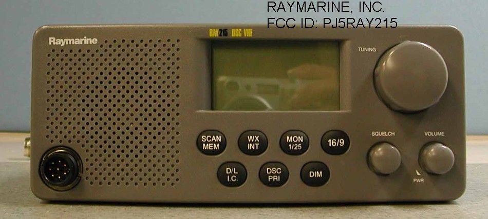
OPERATIONS 1 INTRODUCTION Your RAY215 has the capability to transmit and receive on all available US, International and Canadian Marine VHF radiotelephone channels. There are channels that are FCC approved but may only be used by authorized stations for specific purposes, depending on t he type of vessel (commercial or noncommercial.) Refer to Table of Frequency List. These tables list all marine VHF channels available in your RAY215 for US, International and Canadian radiotelephone use. Full familiarization of these tables is essential when selecting your channe ls to insure proper channe l usage. 2 CONTROLS AND LCD DISPLAY 2.1 Controls 1) Channel Selection (Knob) -. Clockwise rotation increases the channel number and counterclockwise decreases the channe l number. - This knob is also used to select digits and functions in the DSC mode. 2) Volume Knob -. The volume knob controls the audio volume and is also switched to turn power on and off. When the knob is rotated clockwise from the “OFF” position, the radio will power up. Further clockwise rotation increases the volume and counterclockwise rotation decreases volume. The upper bar gra ph o n the LCD displays the volume level. 3) Squelch Knob -. W hen the Squelch kno b is rotated clockwise, the squelch level is increased and when rotated counterclockwise, the squelch level is decreased. The lower bar graph on the LCD displays the squelch level. 4) SCAN/ MEM Key When the key is pressed and released, Alarm-1 is heard and a scan starts or stops. The key operation during a scan will cause the scan to stop, while the operation during stop a scan will start. When plural channels are stored in memory, pressing the key will initiate Memory Scan. In case no channel has been stored in memory, the key operation will initiate All Scan. To initiate All Scan when channels are stored in memory, the key is pressed again during its flashing. Pressing and holding the key for 3 consecutive seconds will store or cancel the current channel in me mory with Alarm-1 put to sound. W hen the current channel has been stored, with the key operation the stored channel is cancelled. If not stored, the key operation will store the current channel in me mo ry . 5) WX/INT Key - When the WX/INT key is pressed and released, the Weather mode will be selected. If pressed and released again, the radio will return to the last used marine channel. -. If pressed and released while in the Dual Watch mode, the unit will enter the Tri-Watch mo de . -. W hen pressed and he ld for 2 seconds, the Frequency Mode (US, CAN, INT) is change d. 6) MON/ 1/25 Key -.When MON/ 1/25 is pressed and released, a tone is heard and the radio initiates the Dual Watch function of the Monitor mode. -. When MON/ 1/25 is pressed and held for 2 seconds, the output power will be changed. 7) 16/9 Key -. When pressed once, the Priority Channel (16 or 9) will be selected. - W hen pressed and he ld for 2 seconds, the priority channel can be change d (fro m 16 to 9 or from 9 to 16). 8) D/L/ IC Key Pressing and releasing the key will place the radio into a desensitization state with an alarm put to sound. The key operation during the desensitization mode will cancel the mode while the key operation during the off state of the desensitization mode will initiate the mode. When the radio is in the mode, the indication [DESENS] is illuminated. Holding the key for 2 consecutive seconds will initiate the Intercom function (the details are described later) between the fist microphone on the base station and the remote Ha nd-set with the Alarm-1 put to sound. - Pressing and releasing the D/L I.C.Key with DSC/PRI key will put the unit to enter the DSC mode. 9) DSC/ PRI Key Pressing and releasing the DSC/PRI Key with D/L I.C. key will put the unit to enter the DSC mode. Operation in the DSC mode includes Individual Ship's Call, All Ship's Call and Distress Call. In any case it is necessary to register Own Ship's ID in advance. The DSC mode may be exited at any time by pressing the [16/9] key. During indication of DSC, no display is given for Volume and Squelch. Function to recover the operation priority to the base station during, the use of the Ha nd-set (option). Pressing and holding the key for 2 consecutive seconds when using the Hand-set will enable the base station to recover the operation priority with the Alarm-1 put to sound. 10) DIM Key Pressing and releasing the key will cha nge LCD back-lighting level with an alarm put to sound. There are four levels to be set ; OFF, Low, Medium and High. At each subsequent pressing, four steps of the level change-over will result. When the key is left not pressed for 5 consecutive seconds, the present level value is entered in EEPROM and setting operation of the back-lighting level is suspended. At re-supply of the power the unit is put on at the same level as stored in EEPROM. Levels repeatable : OFF Low Medium High 11) PTT Key (Fist Microphone) The PTT (Push To Talk) key operation enables the transmitter. When the current channel is selected on either of a Weather CH or a transmission -forbidden channel, the key operation is disabled with the Alarm-2 put to sound. W hen transmission state has been continued for 5 minutes or longer, transmission is interrupted and the Alarm-2 is kept sounding until once releasing the key. (Under the above-mentioned state, although the radio is placed in the receiving mode, no received audio tone is heard as the PTT is held depressed.) 12) Trackpad UP Key (Fist Microphone) -. The UP key increases the channel number by 1 each time it is pressed. If pressed and held, the channel will increment at a rate of 10 per second. 13) Trackpad DOWN Key (Fist Microphone) -. The DOWN key decreases the channel number by 1 each time it is pressed. If pressed and held, the channe l will decre ment at a rate of 10 per second. 14) 16/9 Key (Microphone) -. Has the same function as the 16/9 key on the front panel controls. 15) DISTRESS Key…
Text truncated - open the document above for the full version.
Cover Letter(s)
Raymari ne, I ncorporate d Raymari ne, I ncorporate dRaymari ne, I ncorporate d Raymari ne, I ncorporate d Engineering Division 1800 N W 49th S tr eet Suite 130 Ft. Lauderdale, FL 33309 954.772.9228 954.772.9927 fax www.raymarine.com September 20 , 2001 Federal Communications Commission 7435 Oakland Mills Road Columbia, MD 21046 RE: CONFIDENTIALITY OF RAYMARINE, INC’S MODEL RAY215 To Whom It May Concern: As we have stated in our filing process, Schematics and Block Diagrams for the RAY215 VHF Radio are proprietary information. This information is provided only for the purposes of testing the radio and must remain confidential to protect Raymarine products and designs from its competitors. If you have any questions, please contact me. Sincerely, Engelhard Sundoro Raymarine, Inc. Sr. Electrical Engineer 954-267-8057
ID Label/Location Info
Label for Ray215 Label: 34.5mm x 24.5mm with 4x 1r corners Colors: print black on white label stock
ID Label/Location Info
Label Placement on the Unit
Operational Description
TECHNICAL DESCRIPTION of RAY215 1. Power Supply Section 1.1 This equipment is rated for 13.2 VDC but can operate within a voltage range of 10.8 - 15.6 VDC. In case the input supply voltage exceeds 15.6 VDC, the over-voltage detection circuit (D18, Q27) cuts off the relay (RL1) to the main power supply. Reverse connection of the power supply is protected by a diode (D17) in the relay circuit. 1.2. Pressing the Power switch on the main unit turns on the power supply via the relay circuit (consisting of Q26, Q301, D301 and IC305). Only the CPU system is powered on. The RF circuit (Q29, Q30 and Q331) remains off until the power switch is pressed on the handset. At that time, the full system is operational. 2 Receiver Section The RAY215 is actually equipped with two receiver units, one exclusively for Channel 70 and another for All Channels. 2.1 ANT switch The RF-signal passes through the low-pass filter to the RF pre-amplifier (Q16) via the ANT switch. After receiving a signal, the switch diode (D1-D2) becomes non-conductive. 2.2 Receiver 2.2.1 RF Amplifier The RF amplifier consists of the FET amplifier (Q18) and a BPF having variable bandwidth by a variable capacitance diode (D12-D16). The bandwidth is automatically corrected by the control voltage supplied from the CPU to a proper value corresponding to the receive frequency. The BPF is provided with an attenuation characteristic of 15 dB or larger at the detuning point 3 MHz lower than the lower limit of the receive frequency (156 MHz). Then the RF signal, having been mixed with the 1st local signal* by the 1st mixer (Q19) after passing the BPF, is converted to the 1st IF signal (21.6 MHz). * Note : The 1st local signal generated by a synthesizer has a frequency lower than the desired frequency by 21.6 MHz. The 1st local signal is fed to the 1st mixer (Q19) after being amplified by the buffer amplifier (Q14). 2.2.2. 1st IF The 1st IF signal of 21.6 MHz supplied via the crystal filter (F1) is amplified by the 1st IF amplifier (Q20). 2.2.3 2nd IF The 1st IF signal, having been mixed with the 2nd local signal (21.145 MHz) in the IC (IC7 Mix, Osc, Amp, Limit, Det) for the 2nd IF, is converted into the 2nd IF signal with a frequency of 455 kHz. Further, after subjected to amplification and successive amplitude limitation via the ceramic filter (F2), the signal is demodulated by the Quad detector (quadrature detection) into an audio signal. 2.2.4 De-Emphasis An audio signal is subjected to a correction in the frequency characteristic to -6 dB/oct by the de-emphasis circuit (IC8). 2.2.5 Squelch High frequency noises outside the voice band among the DISC outputs are amplified with the noise amplifier (IC7) and converted into a DC voltage by the detection circuit. Then, the converted voltage is further amplified by the DC amplifier (IC314) to a BUSY1 signal, which is fed to the squelch control port (A/D). The operation level of the squelch is determined by the electronically controlled volume (IC313) and the set value for the A/D action of the CPU. 2.3 WX alert (Weather Channel) The tone decoder (IC11) detects the1050 Hz tone signal in the Weather Channel mode. 2.4 DSC decoding (Channel 70) The DSC signal of 1200 bps is demodulated by the FSK Modem-2 (IC309). 3 Transmitter Section 3.1 IDC Circuit After pre-emphasis of a 6 dB/oct in the IDC circuit (IC6), the microphone, DSC, and ATIS signals from the control system are supplied to an amplitude-limiting circuit. Then the signals are modulated through the fifth low-pass filter for splatter prevention and supplied to the VCO. The maximum frequency deviation is set by VR3. 3.2 Buffer driver amplifier The carrier frequency from the VCO is supplied via the diode switch (D7) to the buffer (Q2). The carrier is then amplified up to about 200 mW, and finally boosted to 25 W by the RF pre-amplifier (IC1) at the final stage. The transmitting power is supplied to the antenna by operating the ANT switch (D1) via the LPF. 3.3 APC circuit The transmitting power is subjected to DC-detection in the detection circuit (D5), then compared with the standard set value of the output at the comparator circuit (IC2). This output controls both the PA and the driver by two-staged DC amplifiers (Q5 and Q6) so that a stable transmitting power can be supplied to the ANT. The switchover of power between 25 W and 1 W is effected with the output changeover switch (Q7). The output is set with the VR: VR1 for 1 W or VR2 for 25 W. 3.4 DSC Encoding The FSK modulating signal of 1200 bps is produced in the FSK Modem-1 (IC308). The modulation index is 2.0 for DSC. 4. PLL Circuit The standard PLL frequency of 12.8 MHz is oscillated and de-multiplied into 25 kHz (= 1/512) by the PLL IC (IC4). The oscillation frequency of the VCO, which has been de- multiplied into 25 kHz just like the standard, is subjected to phase comparison by a phase comparator within an IC, producing a pulse output corresponding to the deviation. The output pulse is converted into a DC value through the externally installed charge pump circuit (Q11 and Q12) and a loop filter. It is supplied to the control terminal of the VCO as a frequency control voltage. A part of the output from the VCO is fed back to the PLL IC (Fin) via the buffer amplifier (Q13). The loop filter is provided with a time-constant changeover- switch using the IC3 to meet the requirement for high-speed response by accelerating the rise characteristic at the time of transmission/reception changeover and frequency changeover. The detection circuit (IC5) enables the PLL unlocking signal to output without fluttering. 5 AF Control Section 5.1 AF Selection An AF signal is input to matrix switch (IC309), selected by the operation of radio then output. 5.2 Application of AF signal: AF signal in the transmitting system -Fist-microphone AF-signal -Hand-set microphone AF signal -FSK signal AF signal in the receiving system -AF Out-1 signal 5.3 Selection/ output of each signal in radio operation Radio in receiv…
Text truncated - open the document above for the full version.
Test Report
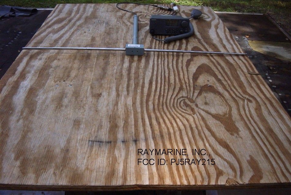
APPLICANT: RAYMARINE, INC. FCC ID: PJ5RAY215 REPORT #: T:\R\RAYMAR\702ZAU1\702ZAU1TestReport.doc TABLE OF CONTENTS TABLE OF CONTENTS LIST APPLICANT: RAYMARINE INC. FCC ID: PJ5RAY215 TEST REPORT: PAGE 1......COVER SHEET - GENERAL INFORMATION & TECHNICAL DESCR. PAGE 2......TECHNICAL DESCRIPTION CONTINUED PAGE 3......MODULATION CHARACTERISTICS & RF POWER OUTPUT PAGE 4......AUDIO FREQUENCY RESPONSE PLOT PAGE 5......MODULATION LIMITING PLOTS – 300 Hz, 1000 Hz PAGE 6......MODULATION LIMITING PLOT – 3000 Hz PAGE 7......AUDIO LOW PASS FILTER PAGE 8......OCCUPIED BANDWIDTH PAGE 9......OCCUPIED BANDWIDTH PLOT – CW PAGE 10......OCCUPIED BANDWIDTH PLOT PAGE 11-13...SPURIOUS EMISSIONS AT ANTENNA TERMINALS PAGE 14......FIELD STRENGTH OF SPURIOUS EMISSIONS PAGE 15......METHOD OF MEASURING RADIATED SPURIOUS EMISSIONS PAGE 16......FREQUENCY STABILITY PAGE 17......LIST OF TEST EQUIPMENT EXHIBIT CONTAINING: EXHIBIT 1.........FCC ID LABEL SAMPLE EXHIBIT 2.........SKETCH OF FCC ID LOCATION EXHIBIT 3A........EXTERNAL PHOTOGRAPH - FRONT VIEW EXHIBIT 3B........EXTERNAL PHOTOGRAPH - REAR VIEW EXHIBIT 3C........EXTERNAL PHOTOGRAPH – TOP VIEW EXHIBIT 3D........EXTERNAL PHOTOGRAPH – BOTTOM VIEW EXHIBIT 3E-3F.....EXTERNAL PHOTOGRAPH – SIDE VIEWS EXHIBIT 3G-3H.....INTERNAL CHASSIS VIEW PHOTOGRAPHS EXHIBIT 3I........EXTERNAL PHOTOGRAPH – RF BOARD - COMPONENT EXHIBIT 3J........INTERNAL PHOTOGRAPH – RF BOARD - SOLDER EXHIBIT 3K........INTERNAL PHOTOGRAPH – CONTROL BOARD – COMPONENT EXHIBIT 3L........INTERNAL PHOTOGRAPH – CONTROL BOARD – SOLDER EXHIBIT 3M........INTERNAL PHOTOGRAPH – FRONT – SOLDER CHASSIS VIEW EXHIBIT 3N........INTERNAL PHOTOGRAPH – FRONT – COMPONENT EXHIBIT 30........INTERNAL PHOTOGRAPH – FRONT - SOLDER EXHIBIT 4A-4B.....TEST SETUP PHTOGRAPHS EXHIBIT 5A-5C.....BLOCK DIAGRAMS EXHIBIT 6A-6C.....SCHEMATICS EXHIBIT 7.........USER'S MANUAL EXHIBIT 8.........TECHNICAL MANUAL APPLICANT: RAYMARINE, INC. FCC ID: PJ5RAY215 REPORT #: T:\R\RAYMAR\702ZAU1\702ZAU1TestReport.doc Page 1 of 17 GENERAL_INFORMATION_REQUIRED FOR_TYPE_ACCEPTANCE 2.1033 (c) (1,2) RAYMARINE INC. will sell the FCC ID: PJ5RAY215 VHF Marine transmitter in quantity, for use under FCC RULES PART 80. 2.202 (c) TECHNICAL_DESCRIPTION 2.1033 (c) (4) (1) Type of Emission: 13K6G3E/13K6F3E For 20 kHz For 25kHz Bn = 2M + 2DK M = 3000 D = 3.8 kHz (Peak Deviation) K = 1 Bn = 2(3.0k) + 2(3.8k)(1) = 6.0 + 7.6 = 13.6 k 80.205(A) ALLOWED AUTHORIZED BANDWIDTH = 20.00 kHz. 2.1033 (c) (5) (2) Frequency Range: 156.025-157.425 MHz 80.215 (e) (3) Power Range and Controls: There is a user Power switch for High/Low Power. 2.1033 (c) (6,7) (4) Maximum Output Power Rating: High 25.0 Watts, Low 1.0Watt into a 50 ohm resistive load. (5) DC Voltages and Current into Final Amplifier: POWER INPUT FINAL AMPLIFIER ONLY High Low Vce = 13.2 Volts Vce = 13.2 VDC Ice = 3.9 A. Ice = 1.4 A. Pin = 51.48 Watts Pin = 18.48 Watts Efficiency = 48 % = 00.05 % APPLICANT: RAYMARINE, INC. FCC ID: PJ5RAY215 REPORT #: T:\R\RAYMAR\702ZAU1\702ZAU1TestReport.doc Page 2 of 17 2.1033(c)(10) (7) Complete Circuit Diagrams: The circuit diagram is included as EXHIBIT 6A-6C. The block diagram is included as EXHIBIT 5A-5C. 2.1033 (c) (3)(8) Instruction book. The instruction manual is included as EXHIBIT #7. 2.1033(c)(9) (9) Tune-up procedure. The tune-up procedure is given in EXHIBIT #7. 2.1033(c)(10) (10) Description of all circuitry and devices provided for determining and stabilizing frequency is included in the circuit description in the instruction manual. 2.1033(c)(13) (11) Digital modulation. This unit does NOT use digital modulation. The data required by 2.1046 through 2.1047 is submitted below. APPLICANT: RAYMARINE, INC. FCC ID: PJ5RAY215 REPORT #: T:\R\RAYMAR\702ZAU1\702ZAU1TestReport.doc Page 3 of 17 2.1033(c)(6) RF_power_output. 80.215(e)(1) RF power is measured by connecting a 50 ohm, re- sistive wattmeter to the RF output connector. With a nominal battery voltage of 13.2V, and the transmitter properly adjusted the RF output measures: POWER OUTPUT HIGH POWER: OUTPUT POWER: 25.0 Watts LOW POWER: OUTPUT POWER: 1.0 Watt METHOD OF MEASURING RF POWER OUTPUT Transmitter 50 ohm under test Resistive Wattmeter Power Supply 2.1047(a) Voice Modulation_characteristics: (a) AUDIO_FREQUENCY_RESPONSE See next page. 80.213 (e) AUDIO_LOW_PASS_FILTER The audio low pass filter is included and the plot is shown in page 7. Rules 80.213(e) for ship stations with a low pass filter. 80.213(d) Audio_input_versus_modulation A plot of the audio input versus deviation is shown in in Pages 5-6. APPLICANT: RAYMARINE, INC. FCC ID: PJ5RAY215 REPORT #: T:\R\RAYMAR\702ZAU1\702ZAU1TestReport.doc Page 4 of 17 Raymarine Company RAY215 -1 1 3 5 7 9 11 13 15 17 100100010000 Frequency rms mVolts audio response APPLICANT: RAYMARINE, INC. FCC ID: PJ5RAY215 REPORT #: T:\R\RAYMAR\702ZAU1\702ZAU1TestReport.doc Page 5 of 17 Modulation Limiting Raymarine Inc. RAY215 0 1000 2000 3000 4000 5000 05101520 rms mVolts Deviation 1000 Hz Raymarine Company RAY215 0 500 1000 1500 2000 051015202530 rms mVolts Deviation 300 Hz APPLICANT: RAYMARINE, INC. FCC ID: PJ5RAY215 REPORT #: T:\R\RAYMAR\702ZAU1\702ZAU1TestReport.doc Page 6 of 17 Raymarine Company RAY215 0 1000 2000 3000 4000 5000 024681012 rms mVolts Deviation 3000 Hz APPLICANT: RAYMARINE, INC. FCC ID: PJ5RAY215 REPORT #: T:\R\RAYMAR\702ZAU1\702ZAU1TestReport.doc Page 7 of 17 APPLICANT: RAYMARINE, INC. FCC ID: PJ5RAY215 REPORT #: T:\R\RAYMAR\702ZAU1\702ZAU1TestReport.doc Page 8 of 17 2.2049(c) Occupied_bandwidth: 80.205(a) Data in the plots shows that on any frequency removed from the assigned frequency by more than 50%, but not more than 100%: At least 25dB. On any frequency removed from the assigned frequency by more than 100%, but not more than 250%: At least 35dB. On any frequency removed from the assigned frequency by more than 250%, of the authorized bandwidth: At least 43+log(P)dB. Radiotelephone transmitter with modulation limiter. Test procedure: TIA/EIA-603 para 2.2.11 , with the exc…
Text truncated - open the document above for the full version.
Contact Information
Applicant
Roy C Ediss(Approvals Engineer)
Technical Contact
Timco Engineering, Inc.Mario R de Aranzeta
[email protected]888-472-2424
849 NW State Road 45 · Newberry, Florida · United States
Non-Technical Contact
Timco Engineering, Inc.Sharon A Hoffman
[email protected]888-472-2424
Test Firm
Timco Engineering, Inc.S Sanders
Technical Specifications
| # | Rule Parts | Frequency Range | Power Output | Emission | Tolerance |
|---|---|---|---|---|---|
| 4 | 8 | 156.025 MHz - 157.425 MHz | 1 W | 16K0G3E | 0.001 % |
Other Applications from Flir Belgium BVBA
PJ5-AX2PLUS
Apr 20, 2026Fish finder with Bluetooth and 2.4GHz Wi-Fi
Equipment Class
DSS - Part 15 Spread Spectrum Transmitter
PJ5-RAY901
Jun 08, 2022RAY91 VHF Black Box with AIS Rx
Equipment Class
TNB - Licensed Non-Broadcast Station Transmitter
PJ5-953LPSSR
Jun 28, 2021Non-SOLAS solid state marine radar
Equipment Class
MRD - Marine Radar
PJ5-953MPSSR
Jun 28, 2021Non-SOLAS solid state marine radar
Equipment Class
MRD - Marine Radar
PJ5-RAY4GHUB
Apr 18, 2021YachtSense Link Marine Cloud Router
Equipment Class
NII - Unlicensed National Information Infrastructure TX