PJ5RAY54VHF/FM marine transceiver with class D DSC
Flir Belgium BVBA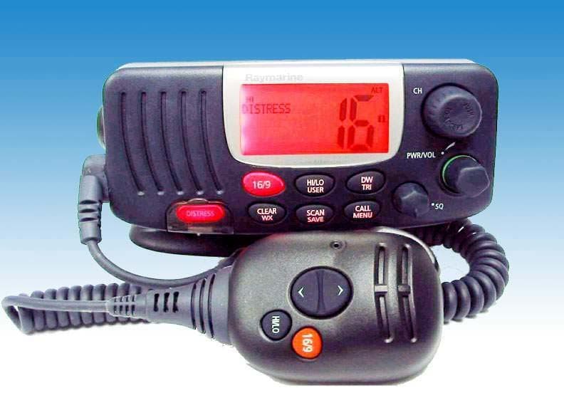
Click to zoom
Application Details
- Equipment Class
- TNB - Licensed Non-Broadcast Station Transmitter
- Date of Grant
- May 23, 2004
- Application Purpose
- Original Equipment
- Date of Application
- May 23, 2004
- Equipment Note
- VHF/FM marine transceiver with class D DSC
- Frequency Range
- 156.02500000 - 157.42500000
- Company
- Flir Belgium BVBA
- Country
- Belgium
Documents & Files
Document Text
Text extracted from the exhibit documents filed with the FCC. Open a document above to read the original.
Users Manual
Ray54 Marine VHF Radio Owner’s Handbook Document number: 81231-1 Date: April2004 81231_1.book Page i Thursday, April 22, 2004 5:21 PM 81231_1.book Page ii Thursday, April 22, 2004 5:21 PM i About this Handbook Introduction This handbook describes the Ray54 fixed VHF marine radio. The Ray54 provides two-way communications on all US, Canadian and International marine channelsand seven weather channels. Conventions Used Throughout this handbook, the dedicated (labelled) keys are shown in bold capitals (for example: SCAN/SAVE). The LCD indicators and functions are shown in normal capitals (for example: TX). ➤Operating procedures, which may consist of a single key-press or a sequence of numbered steps, are indicated by an arrow icon shown in the margin. Technical Accuracy To the best of our knowledge, the information in this handbook was correct as it went to press. However, our policy of continuous product improvement and updating may change specifications without prior notice. As a result, unavoidable differences between the product and handbook may occur from time to time. Raymarine cannot accept liability for any inaccuracies or omissions it may contain. For the latest product information visit our website: www.raymarine.com Warranty To register your new Raymarine product, please take a few minutes to fill out the warranty registration card found at the end of this handbook. It is very important that you complete the owner information and return the card to the factory in order to receive full warranty benefits. 81231_1.book Page i Thursday, April 22, 2004 5:21 PM iiRay54 VHF Radio Important Information Raymarine radios comply with the Federal Communications Commission (FCC) and Industry Canada requirements that regulate marine VHF radio usage for the US and Canada, respectively. Marine VHF radio users in the US must comply with all applicable FCC rules and regulations, some of which are described in this handbook. This information was current at the time this handbook was printed. Up-to- date information, including licensing requirements, can be obtained on the FCC website at: www.fcc.gov/wtb/marine Official FCC forms can be obtained on the FCC website at: www.fcc.gov/formpage.html FCC Notice This device complies with part 15 of the FCC Rules. Operation is subject to the following two conditions: (1) This device may not cause harmful interference, and (2) this device must accept any interference received, including interference that may cause undesired operation. Changes or modifications to this equipment not expressly approved in writing by Raymarine, Incorporated could violate compliance with FCC rules and void the operator’s authority to operate the equipment. Station License An FCC Ship Radio Station License and Call Sign are not required for most recreational vessels travelling in US waters. However, you must obtain a license if your vessel travels to foreign ports. Ships that use MF/HF single side-band radio, satellite communications, or telegraphy must be licensed by the FCC. If necessary, you can obtain a Station License by filing FCC Form 605, which is available from the FCC website listed above. 81231_1.book Page ii Thursday, April 22, 2004 5:21 PM iii Operator License An Operator License is not required to operate a VHF Marine Radio within US territorial waters. However, a license is required to operate the radio if you dock in a foreign port (including Canada and Mexico) or leave a foreign port to dock in a U.S. port. You can request a Restricted Radiotelephone Operator Permit from the FCC by filing Form 753. INDUSTRY CANADA You do not need a license to operate this radio within sovereign waters of Canada or the US. You will need a license to operate this radio outside of Canada or the US. To obtain Industry Canada licensing information, contact the nearest field or regional office, or write: Industry Canada Radio Regulatory Branch Attention: DOSP 300 Slater Street Ottawa, Ontario Canada, KIA OC8 The following information about the radio is required to complete the license application: Industry Canada Certification Number ----------------- FCC Type Number -------------------------- FCC Type Accepted Parts 15 and 80------------------ Output Power 1 watt (low) & 25 watts (high)----------------- Modulation 16FE (FM)---------------------------- Frequency Range 156.025-157.425----------------------- Maritime Mobile Service Identity (MMSI) The Ray54 includes equipment for Digital Selective Calling (DSC). A nine- digit Maritime Mobile Service Identity (MMSI) number is required to operate the DSC equipment. You can request an MMSI number from the FCC when you apply for a Station License. If your vessel does not require a license, you may obtain an MMSI by contacting either BoatUS (www.boatus.com) or MariTEL (www.maritelusa.com). Once obtained, you can program the MMSI number into your Ray54 as described in this handbook. 81231_1.book Page iii Thursday, April 22, 2004 5:21 PM ivRay54 VHF Radio Group MMSI ID A Group ID MMSI number can also be entered for vessels that are part of a group, such as a flotilla or racing fleet, enabling DSC communications within the group. Remember: •Maintain a radio watch on Channel 16. Channel 16 is used for distress and safety purposes only. •VHF Channel 70 is used only for Digital Selective Calling (DSC). It can not be used for general-purpose calling. •Your VHF transceiver has a high low power switch. Use low power whenever feasible. Unnecessary high-power operations can interfere with other important communications. •Always use your radio call sign at the beginning and end of each trans- mission. •Be sure only qualified persons operate your radio. You are responsible for control of your radio. Know the rules. •Limit calls to other vessels to 30 seconds. If you receive no reply, wait 2 minutes; then try again. Keep communications brief and avoid chit-chat. •Never transmit false distress messages, and never use profanity on the air. 81231_1.book Page iv…
Text truncated - open the document above for the full version.
Users Manual
Chapter 5: Digital Select Calling (DSC)37 Chapter 5: Digital Select Calling (DSC) The Digital Selective Calling (DSC) protocol is a globally applied system used to send and receive digital calls. DSC uses a unique Maritime Mobile Service Identity (MMSI) number to direct DSC calls directly to your radio, much like a telephone number.When the DSC signal is received, the radio quickly switches over to Channel 70 and performs the corresponding operation. Note: An MMSI number is required to operate the DSC equipment in this ra- dio. You can program the MMSI number yourself one time only using the Menu Operation described in this handbook. Otherwise, your Raymarine dealer can program or change the number for you. When a DSC call is received, the Ray54 Base Station automatically responds based on the type of call. When receiving a DSC call from another vessel or a coast station, an alert sounds and DSC data appears in the LCD – such as time of a call, the caller and the type and priority of a call. DSC calls fall into four categories: •INDIVIDUAL calls are made to a specific station identified by its MMSI number. See page 39. •GROUP calls send transmissions that are only received by radios that share a common Group MMSI number. See page 46. •ALL SHIPS calls send out a message to all vessels within range that you wish to send a Safety or Urgency message but the situation is not serious enough for a Distress Call. See page 50. •DISTRESS calls send your vessel’s position and time information to other ships and shore stations, along with (optionally) the nature of your Distress situation. See page 55. •POSITION REQUEST calls enable you to request GPS position infor- mation from any vessel for which an MMSI number is known. DSC calls (except Distress) are designated as: •ROUTINE for normal calls •SAFETY for advisory alerts •URGENCY for assistance when life is not in immediate danger 81231_1.book Page 37 Thursday, April 22, 2004 5:21 PM 38Ray54 VHF Radio 5.1DSC Call Function Call Mode is used to initiate DSC Individual, Group, All Ships and Distress calls, to request GPS position information for another vessel and to access the Call Logs and Phonebook.The channel remains unchanged and you can perform normal TX operation. DSC mode is exited when transmitting. Press and release the CALL/MENU key while in normal operation mode to enter DSC Call Mode. The Ray54’s call type and structure are as follows: Calls the Ray54 can make:Calls the Ray54 can receive: Individual RoutineIndividual Safety, Urgency and Routine Group RoutineGroup Routine All Ships Safety and UrgencyAll Ships Safety, Urgency and Routine DistressDistress, including Distress ACK and Distress Relay Position Request 81231_1.book Page 38 Thursday, April 22, 2004 5:21 PM Chapter 5: Digital Select Calling (DSC)39 5.2 Individual Calls The Ray54 can make Individual Routine calls and receive Individual Safety, Urgency and Routine calls. Making Calls to Coast Stations The examples in this handbook illustrate making calls to Ship Stations. However, the procedures for making Individual Calls to a Coast Station are different. Calls to a Ship Station require that you enter a subsequent working channel chosen from a pre-programmed list offered to you by the Ray54. Call TypeDescription INDIVIDUALMakes a ROUTINE DSC call to a specific station identified by its MMSI number. GROUPSends transmissions that are only received by radios that share a common Group MMSI number. Up to 3 Group MMSI numbers can be stored and called. ALL SHIPSSends out a message to all ships within range that you need assistance but the situation is not serious enough for a Distress Call. This call should only be used if hailing for assistance on channel 16 fails. There are two types of All Ships Calls: SAFETY for advisory alerts and URGENCY for assistance when life is not in immediate danger. DISTRESSSends out the position and time information from the input NMEA data along with your MMSI number. This digital information lets other ships and shore stations equipped with appropriate DSC equipment know where you are and that you are in a Distress situation. POSITION REQUEST This option enables you to request GPS position information from any ves- sel for which an MMSI number is known. You can specify the target vessel either by selecting it from your MMSI phonebook or by manually entering its MMSI number. RX CALL LOGA list of all received call types (except Distress calls) by number and time of call. The log maintains up to 20 calls; the earliest call is stored at the end of the list. After more than 20 calls have been received, the call at the end of the list is automatically overwritten. An Individual Call can be placed to the selected MMSI/NAME in the log. DISTRESS LOGLists all stored Distress calls by number and time of call.The log maintains up to 20 calls; the earliest call is stored at the end of the list. After more than 20 calls have been received, the call at the end of the list is automat- ically overwritten. An Individual call can be placed to the selected MMSI/ NAME in the log. NOTE: Received Distress Relay calls are also stored in the Distress Log. 81231_1.book Page 39 Thursday, April 22, 2004 5:21 PM 40Ray54 VHF Radio Calls to a Coast Station remove this step from the operating procedures: the Coast Station controls and indicates the subsequent working channel within its acknowledgement. The Ray54E automatically detects the correct procedures for you based on the type of MMSI number you enter manually or with or the phonebook. If “00” is detected as the first two characters of the MMSI, Coast Station procedures are implemented automatically. Transmitting an Individual Call Using the Phonebook To call another ship or coast station, you must select the specific MMSI number to contact and the working channel to be used for the call. The MMSI number can be entered manually or selected from a Phonebook list of preprogrammed numbers specified using the MENU function. 1.Press and…
Text truncated - open the document above for the full version.
Users Manual
Chapter 6: Menu Settings73 Chapter 6: Menu Settings 6.1 Menu Function The radio’s setup functions are accessed through the Menu mode. Menu mode selections are as follows. ItemDescription PHONEBOOKA list of frequently-called DSC stations that you can select for making an individual call. Up to 20 Phonebook entries can be stored. LOCAL/DISTLOCAL mode eliminates noise, but degrades receiver sensitivity. DISTANT mode enables normal receiver sensitivity. BACKLIGHTINGSelects the backlight levels for the LCD, base station keypad and micro- phone keypad. CONTRASTSelects the LCD contrast setting. GPS/TIME Used to manually set latitude/longitude position and UTC time for a DSC distress message. Also selects how the data is displayed on the LCD. RADIO SETUP Selects four separate radio settings: a) BAND – Frequency Group (US, International, Canadian) b) CH NAME – Descriptive name for each channel (up to 11 characters) c) RING VOLUME – Alarm tone volume (LOUD or SOFT) d) KEY BEEP – Key beep volume (LOUD, SOFT or OFF) DSC SETUP Selects the following DSC settings: a) MY MMSI ID – Used for one-time entry of the MMSI number required for DSC functions. If already programmed, displays the saved MMSI ID number. b) GROUP SETUP – Stores up to 3 Group MMSI IDs and associated Names c) POS REPLY – Selects how Position Request data is transmitted d) AUTO CH C HG – Selects whether your radio automatically switches to the requested working channel when DSC Calls are received. RESETEnables a return to factory default settings. 81231_1.book Page 73 Thursday, April 22, 2004 5:21 PM 74Ray54 VHF Radio ➤To access the Menu Mode: 1.Press and hold the CALL/MENU key to enter menu mode. The list of available functions appear on the dot matrix display. 2. Rotate the CH knob to scroll down the list until the arrow points to the desired function. Push the CH knob to accept. To exit the Menu mode or sub-mode, press the 16/9 or CLEAR/WX keys, or else select the EXIT option from the menu. >PHONEBOOK LOCAL/DIST BACKLIGHT CONTRAST >RADIO SETUP DSC SETUP RESET EXIT 81231_1.book Page 74 Thursday, April 22, 2004 5:21 PM Chapter 6: Menu Settings75 6.2 DSC Phonebook The Phonebook stores up to 20 preprogrammed MMSI numbers that you can select for making an individual call. The numbers are stored by name and contain the station’s MMSI number. You can add, edit and delete entries from the Phonebook, much as you would on a cellular telephone. Rotate the CH knob to make an item appear on the dot matrix display and then press in the CH knob to select that item. Note: The following examples demonstrate making calls to other ships. You may also make DSC calls to shore stations. Shore MMSI numbers start with “00”. Adding an Entry 1.Press and hold the CALL/MENU knob. The Menu screen appears on the dot matrix display. 2. Press the CH knob to select Phonebook. The Phonebook screen appears. 3. Press and release the CH knob to select <NEW ENTRY>. PHONEBOOK PHONEBOOK >PHONEBOOK LOCAL/DIST BACKLIGHT CONTRAST ><NEW ENTRY> CALL ME AL FINTASTIC OCEANEER ENTER NAME: ____________ ENTER MMSI: _________ 81231_1.book Page 75 Thursday, April 22, 2004 5:21 PM 76Ray54 VHF Radio 4. Rotate the CH knob to scroll through values for the first character in the NAME field. All alpha and numeric characters are available. The first available char- acter is a blank (space). The final available character is an arrow, which serves as a backspace. A total of 12 character spaces are available. When the desired character appears, press and release the CH knob to accept it. The next position is ready to be selected. 5. Continue this process until all NAME characters are selected. Press and hold the CH knob to accept the name and move on to the MMSI ID. 6. Use same procedure to enter the MMSI characters. 7. When all characters have been selected, press and hold the CH knob to accept. The new entry appears in the Phonebook. ENTER NAME: B___________ ENTER MMSI: _________ ENTER NAME: BAHAMA MAMA_ ENTER MMSI: _________ ENTER NAME: BAHAMA MAMA ENTER MMSI: 8669823__ <NEW ENTRY> >BAHAMA MAMA CALL ME AL FINTASTIC 81231_1.book Page 76 Thursday, April 22, 2004 5:21 PM Chapter 6: Menu Settings77 Editing an Existing Entry 1. From the Phonebook, rotate the CH knob until the arrow on the dot matrix display points to entry you wish to edit. 2. Push in the CH knob to select the name. 3. Push the CH knob again to select EDIT. 4. Make your changes, using the CH knob. 5. When finished, press and hold the CH knob to accept. The revised name appears in the list. PHONEBOOK <NEW ENTRY> FINTASTIC >OCEANEER SLIM JIM ID523556232 >EDIT DELETE EXIT NAME: OCEANEER MMSI ID: ID523556232 NAME: OCEAN_ER MMSI ID: ID523556232 <NEW ENTRY> FINTASTIC >OCEAN EAR SLIM JIM 81231_1.book Page 77 Thursday, April 22, 2004 5:21 PM 78Ray54 VHF Radio Deleting an Existing Entry 1. From the Phonebook, rotate the CH knob until the arrow on the dot matrix display points to entry you wish to delete. 2. Push the CH knob to select the name. 3. Rotate the CH knob until the arrow is pointing to DELETE. 4. Push the CH knob. The entry is removed. 6.3 Local / Distant This mode toggles between full receiver sensitivity (Distant mode) and attenuated receiver sensitivity (Local mode). Local mode is used is used to decrease unwanted reception (noise). Local Mode is commonly used in areas where interference, usually from shore based paging systems, is high. PHONEBOOK <NEW ENTRY> FINTASTIC >OCEAN EAR SLIM JIM ID523556232 >EDIT DELETE EXIT ID523556232 EDIT >DELETE EXIT ><NEW ENTRY> CALL ME AL FINTASTIC SLIM JIM 81231_1.book Page 78 Thursday, April 22, 2004 5:21 PM Chapter 6: Menu Settings79 ➤To select the sensitivity setting: 1.Press and hold the CALL/MENU key to enter Menu mode. 2. Rotate the CH knob to scroll down the list until the arrow points to LOCAL/ DIST. 3. Push the CH knob to accept. The LOCAL/DIST screen appears. 4. Rotate the CH knob until the arrow points to the desired mode: LOCAL or DISTANT. Push the CH knob to accept. While in loca…
Text truncated - open the document above for the full version.
Attestation Statements
Raymarine, Inc. 22 Cotton Road, Unit D Nashua NH 03063 4219 USA 603 881-5200 800-539-5539 (Fax) www.raymarine.com Rev. 1/1/03 Federal Communications Commission Authorization and Evaluation Division We hereby declare that the Ray54 complies with the following FCC regulations: • Part 80.203 (b), (c) and (n) • Part 80.207 (a), (b) and (d) • Part 80.225 (a) and (c) Sincerely, Keith Wansley Raymarine, Inc. VP of Sales Tel: 603-881-5200 EXT 4831 [email protected]
Cover Letter(s)
Raymarine, Inc. 22 Cotton Road, Unit D Nashua NH 03063 4219 USA 603 881-5200 800-539-5539 (Fax) www.raymarine.com Federal Communications Commission Authorization and Evaluation Division Confidentiality Request regarding application for certification of FCC ID: PJ5RAY54 Pursuant to Sections 0.457 and 0.459 of the Commission’s Rules, we hereby request confidential treatment of information accompanying this application as outlined below: • Schematics • Block Diagrams • Bill of Materials The above materials contain trade secrets and proprietary information not customarily released to the public. The public disclosure of these materials may be harmful to the applicant and provide unjustified benefits to its competitors. The applicant understands that pursuant to Section 0.457 of the Rules, disclosure of this application and all accompanying documentation will not be made before the date of the Grant for this application. Sincerely, Keith Wansley Raymarine, Inc. VP of Sales Telp: 603-846-4831 [email protected] Rev. 1/1/03
Cover Letter(s)
Raymarine, Inc. 22 Cotton Road, Unit D Nashua NH 03063 4219 USA 603 881-5200 800-539-5539 (Fax) www.raymarine.com April 22, 2004 BABT 34 Molesey Road Walton on Thames Surrey KT12 4RQ Dear Sir or Madam: We, Raymarine Incorporated of 22 Cotton Road Unit D, Nashua, NH 03063-4219 hereby authorize T‹V Product Service Limited of Segensworth Road, Fareham, Hampshire, United Kingdom PO15 5RH to act as our agent in all matters relating to applications for equipment authorization, including the signing of all documents relating to these matters. I further certify that neither the applicant nor any party to the application is subject to a denial of Federal benefits, including FCC benefits, pursuant to Section 5301 of the Anti-Drug Abuse Act of 1988, 21 U.S.C. Section 862. This authorization expires on April 21, 2005. Sincerely, Keith Wansley Vice President of Sales Tel: +1 603-881-5200 EXT 4831 Fax: +1 603-864-4756 [email protected]
External Photos
FCC ID PJ5RAY54 © Not to be reproduced without the permission of TÜV Product Service Limited.Page 1 of 11 EXTERNAL PHOTOGRAPHS OF EQUIPMENT FOR RAY54 FOR VHF RADIO PHOTOGRAPHS OF EQUIPMENT RAY54 – Bottom View FCC ID PJ5RAY54 © Not to be reproduced without the permission of TÜV Product Service Limited.Page 2 of 11 PHOTOGRAPHS OF EQUIPMENT RAY54 – Hanmic Bottom View FCC ID PJ5RAY54 © Not to be reproduced without the permission of TÜV Product Service Limited.Page 3 of 11 PHOTOGRAPHS OF EQUIPMENT RAY54 – Handmic Side View 1 FCC ID PJ5RAY54 © Not to be reproduced without the permission of TÜV Product Service Limited.Page 4 of 11 PHOTOGRAPHS OF EQUIPMENT RAY54– Handmic Side View 2 FCC ID PJ5RAY54 © Not to be reproduced without the permission of TÜV Product Service Limited.Page 5 of 11 PHOTOGRAPHS OF EQUIPMENT RAY54– Handmic Top View FCC ID PJ5RAY54 © Not to be reproduced without the permission of TÜV Product Service Limited.Page 6 of 11 PHOTOGRAPHS OF EQUIPMENT RAY54 – Rear View FCC ID PJ5RAY54 © Not to be reproduced without the permission of TÜV Product Service Limited.Page 7 of 11 PHOTOGRAPHS OF EQUIPMENT RAY54 – Side View 1 FCC ID PJ5RAY54 © Not to be reproduced without the permission of TÜV Product Service Limited.Page 8 of 11 PHOTOGRAPHS OF EQUIPMENT RAY54– Side View 2 FCC ID PJ5RAY54 © Not to be reproduced without the permission of TÜV Product Service Limited.Page 9 of 11 PHOTOGRAPHS OF EQUIPMENT RAY54 – Side View 3 FCC ID PJ5RAY54 © Not to be reproduced without the permission of TÜV Product Service Limited.Page 10 of 11 PHOTOGRAPHS OF EQUIPMENT RAY54 – Top View FCC ID PJ5RAY54 © Not to be reproduced without the permission of TÜV Product Service Limited.Page 11 of 11 PHOTOGRAPHS OF EQUIPMENT RAY54 Front View
Internal Photos
FCC ID PJ5RAY54 © Not to be reproduced without the permission of TÜV Product Service Limited.Page 1 of 13 INTERNAL PHOTOGRAPHS OF EQUIPMENT FOR RAY54 FOR VHF RADIO PHOTOGRAPHS OF EQUIPMENT 2nd top&gps filter top unit and assembly view FCC ID PJ5RAY54 © Not to be reproduced without the permission of TÜV Product Service Limited.Page 2 of 13 PHOTOGRAPHS OF EQUIPMENT 2nd unit bottom view FCC ID PJ5RAY54 © Not to be reproduced without the permission of TÜV Product Service Limited.Page 3 of 13 PHOTOGRAPHS OF EQUIPMENT 2nd unit top view FCC ID PJ5RAY54 © Not to be reproduced without the permission of TÜV Product Service Limited.Page 4 of 13 PHOTOGRAPHS OF EQUIPMENT cpu and lcd unit top view FCC ID PJ5RAY54 © Not to be reproduced without the permission of TÜV Product Service Limited.Page 5 of 13 PHOTOGRAPHS OF EQUIPMENT cpu unit bottom and assembly FCC ID PJ5RAY54 © Not to be reproduced without the permission of TÜV Product Service Limited.Page 6 of 13 PHOTOGRAPHS OF EQUIPMENT cpu unit bottom view FCC ID PJ5RAY54 © Not to be reproduced without the permission of TÜV Product Service Limited.Page 7 of 13 PHOTOGRAPHS OF EQUIPMENT gps filter unit bottom view FCC ID PJ5RAY54 © Not to be reproduced without the permission of TÜV Product Service Limited.Page 8 of 13 PHOTOGRAPHS OF EQUIPMENT gps filter unit bottom view-1 FCC ID PJ5RAY54 © Not to be reproduced without the permission of TÜV Product Service Limited.Page 9 of 13 PHOTOGRAPHS OF EQUIPMENT mic unit bottom view FCC ID PJ5RAY54 © Not to be reproduced without the permission of TÜV Product Service Limited.Page 10 of 13 PHOTOGRAPHS OF EQUIPMENT mic unit top view FCC ID PJ5RAY54 © Not to be reproduced without the permission of TÜV Product Service Limited.Page 11 of 13 PHOTOGRAPHS OF EQUIPMENT rf unit bottom view FCC ID PJ5RAY54 © Not to be reproduced without the permission of TÜV Product Service Limited.Page 12 of 13 rf unit top and assembly view FCC ID PJ5RAY54 © Not to be reproduced without the permission of TÜV Product Service Limited.Page 13 of 13 rf unit top view
Operational Description
Page: 1 of 8 THEORY OF OPERATION Ray54/E For Raymarine 2004 Feb 27 This PLL controlled VHF marine mobile transceiver provides an accurate and stable multi-channel operation. The transceiver consists of 13 main sections !" Transmitting stage !" Receiving stage !" Local oscillator PLL (Phase Lock Loop) Circuit !" Memory backup !" Low voltage detection !" Large LCD !" Local/distance Circuit !" 2nd Receiver !" WX Alert Circuit (only USA) !" PC Program !" DSC Feature !" GPS Message !" ATIS Feature (only EU) !" Transmitter Stage The audio is picked up from the internal Mic. The audio signal is then amplified by Audio Amplifier, IC205C , IC205B and filtered by a low pass filter IC10C, IC10D. The audio that is adjusted by VR3 to obtain a suitable RF frequency-deviation, modulates the carrier of VCO, through Varicap (VD302). The modulated signal output from the VCO is pre-amplified by Q2, and IC1 . When the supply voltage is 13.6V, this signal will be amplified up to 1W or 25W. The signal is filtered by low-pass filter circuit of which consists of L1, L2, L4, C1, C2, C3, C5, C6, C14, C47 and C62.These low pass filters are necessary to suppress the second and the third harmonics as higher. The signal is then fed into the antenna input and radiated out. The signal is also fed into another path consisting of C9, C10, D3, D4 for sampling, and is converted into a direct current voltage for the Automatic Power Control (APC) circuit IC12, Q5, Q14, Q15, Q24 to control the voltage of IC1 Pin 2 to maintain the output power stability. Q15 is used control Hi/Lo power When the unit is transmitting, the channel control voltage is added to the TX VCO varicap VD306. The capacitance of VD302 is varied following the audio signal, therefore the carrier is modulated to form the modulated signal. Page: 2 of 8 !" Receiver Stage The receiver uses a double frequency super-heterodyne circuit. The first Immediate Frequency (IF) is 21.4 MHz and the second is 450 kHz. The RF signal is received by the antenna, and passes through a low-pass filter network L1, L2, L3, L9, C1, C2, C3, C5, C6, C14, C47 and C62 to filter out unwanted signal. The received RF signal then passes through a high RF transformer L10 and is amplified by RF amplifier Q9. L11, L12, L13, C15, C18, C20 form the band pass filter. The RF signal then is mixed with the local oscillation frequency by the mixer D22, D23. The first IF (Immediate Frequency) 21.4 MHz is produced. This IF is passed through a coil T2 and a pair of crystal filter F1, F2 to further filter out other unwanted signals. The first IF then is amplified by Q11 and the IF amplifier IC7. (IC7 is an integrated IF amplifier which consists of a local oscillator, a demodulator, a second mixer, squelch control circuit, and IF amplifier). The 21.4 MHz IF then is mixed here with second mixer and converted into 2nd Immediate Frequency (IF) 450 kHz. The 2nd IF passes through a ceramic filter F4 to filter out the residue unwanted signal at pin 5 of IC7 output this final IF signal and The demodulated AF signal is output at pin 9 of IC7. The demodulated AF signal pass through IC15 then passes through a volume control VR201 through de-emphasis circuit feeding IC10A, IC10B.and finally amplified by Audio amplifier IC11 and heard in the speaker. The squelch control signal also produced by IC7, the rectified noise signal is output by Pin 14 of the IC7. Pass through the network by composition of C170, R44 are sends the digital squelch control signal to the MCU to mute the audio speaker path and to indicate the RX station on LCD, R214, R217 and VR203 form a variable resistor, which correspond to the squelch level. !" Local oscillator PLL (Phase Lock Loop) Circuit: The receiver and transmitter both share the same PLL (Phase Lock Loop) Circuitry to produce the carrier frequency or the receiver local oscillation frequency. The local oscillator consists of a fundamental frequency oscillator Q301 and A phase Lock Loop (PLL) IC16 When Rx 5Vvoltage is supply, the VCO will produce receiver local oscillator frequency. The high stability frequency is determined by crystal X2 (20.950 MHz) and as the PLL reference oscillator. This signal is frequency-divided by IC16 and a 12.5 kHz signal is produced. When the VCO frequency applied to IC16 pin1 and frequency-divided by IC2 produces a frequency comparable to 12.5 kHz, PLL IC pin 3 will output a PD voltage to control the VCO. When these two frequencies are matched, a constant control voltage is output from PLL to lock VCO in desired frequency. Otherwise the PLL IC pin 5 will also output a unlock indication to MCU to indicate that the PLL is in the frequency unlock state. Page: 3 of 8 !" Memory Backup IC201 is an EEPROM AT24C64, which acts as a memory backup for the working channel code and the system parameters. Every time when the unit is switched on, the MCU will reset the system, clear the RAM, and recall the memory from the EEPROM to refresh the RAM in MCU IC203. !" Low Voltage Detection The battery voltage divided byR250 and R251 through R254 is input to IC203 for voltage level detection. If the battery voltage drops below 9.5 V, LCD will indicate the battery is in low state. !" Large LCD All message through series bus from MCU to display driver IC401 and will be displayed through a 34 × 52mm 4 × 12 characters dot matrix LCD display. !" Local/distance circuit Local/distance circuits are composed of Q16, R195 and R88. When local SW is on high level, receiver sensitive is high otherwise is on low. !" 2nd Receiver 2nd receiver circuit is as figure. RF input is from C101 of main PCB, the received RF signal then passes through a high RF transformer L505 and is amplified by RF amplifier Q501, L506, L507, L508, C15, C18, C20 form the band pass filter. T…
Text truncated - open the document above for the full version.
Contact Information
Applicant
Roy C Ediss(Approvals Engineer)
Technical Contact
Raymarine IncEngelhard Sundoro
[email protected]+1 954 772 9228
1800 NW 49th Street, Suite 130 · Fort Lauderdale, Florida · United States
Test Firm
TUV SUD Product ServiceJensen Adams
Technical Specifications
| # | Rule Parts | Frequency Range | Power Output | Emission | Tolerance |
|---|---|---|---|---|---|
| 3 | 8 | 156.025 MHz - 157.425 MHz | 25 W | 16K0G2B | 10 ppm |
Other Applications from Flir Belgium BVBA
PJ5-AX2PLUS
Apr 20, 2026Fish finder with Bluetooth and 2.4GHz Wi-Fi
Equipment Class
DSS - Part 15 Spread Spectrum Transmitter
PJ5-RAY901
Jun 08, 2022RAY91 VHF Black Box with AIS Rx
Equipment Class
TNB - Licensed Non-Broadcast Station Transmitter
PJ5-953LPSSR
Jun 28, 2021Non-SOLAS solid state marine radar
Equipment Class
MRD - Marine Radar
PJ5-953MPSSR
Jun 28, 2021Non-SOLAS solid state marine radar
Equipment Class
MRD - Marine Radar
PJ5-RAY4GHUB
Apr 18, 2021YachtSense Link Marine Cloud Router
Equipment Class
NII - Unlicensed National Information Infrastructure TX