PJ5VHFGEN1Fixed Mount VHF marine radio
Flir Belgium BVBA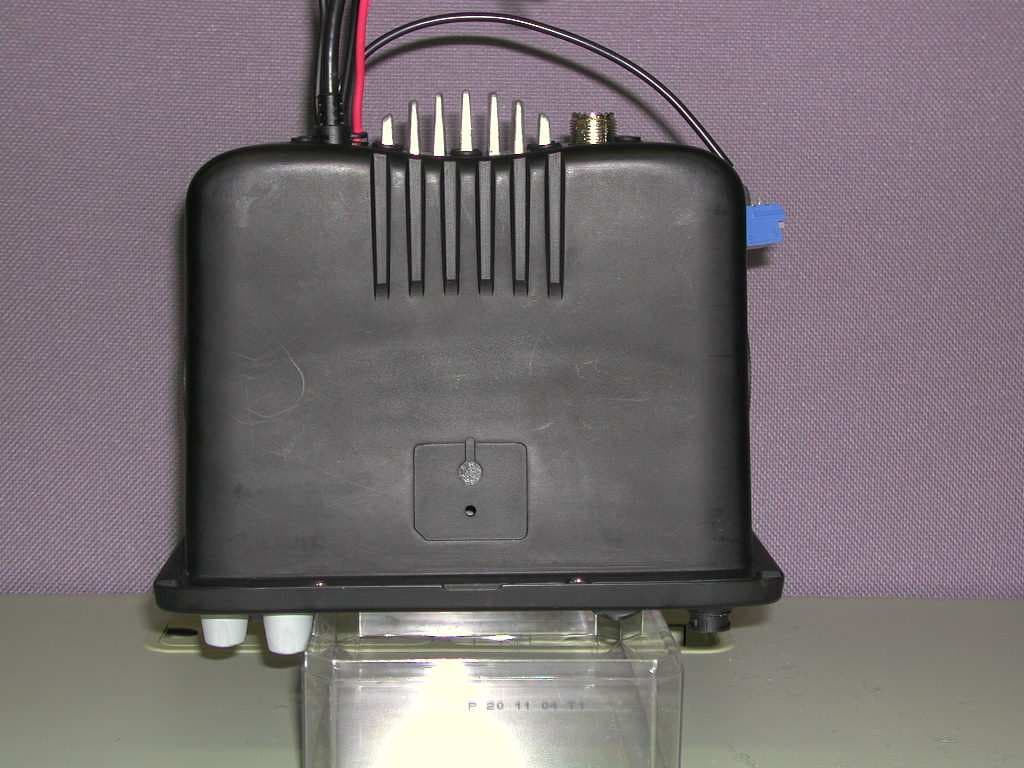
Click to zoom
Application Details
- Equipment Class
- TNB - Licensed Non-Broadcast Station Transmitter
- Date of Grant
- Mar 26, 2007
- Application Purpose
- Original Equipment
- Date of Application
- Mar 26, 2007
- Equipment Note
- Fixed Mount VHF marine radio
- Frequency Range
- 156.02500000 - 157.42500000
- Company
- Flir Belgium BVBA
- Country
- Belgium
Documents & Files
Document Text
Text extracted from the exhibit documents filed with the FCC. Open a document above to read the original.
Users Manual
Ray218 & Ray55 Marine VHF Radio Owner’s Handbook Document number: 81278-1 Date: December 2006 Trademarks and registered trademarks Raymarine is a registered trademark of Raymarine plc. All other product names are trademarks or registered trademarks of their respective owners. Contents of this handbook © Raymarine 2006 Contents Trademarks and registered trademarks ............................................ 2 About this Handbook .............................................................................................9 Important Information .......................................................................................10 Antenna Mounting and EME Exposure ................................................ 12 Safe Compass Distance ........................................................................ 12 EMC Conformance ............................................................................... 12 Chapter 1: Introduction .....................................................................................13 1.1 Ray218 and Ray55 Fixed Station VHF Radios ....................................... 13 1.2 Features ............................................................................................... 13 Digital Selective Calling (DSC) .............................................................. 14 Chapter 2: Installation .......................................................................................15 2.1 Unpacking and Inspection .................................................................... 15 Equipment Supplied ............................................................................. 15 2.2 Planning the Installation ...................................................................... 16 2.3 Cable Connections ............................................................................. 19 Power ................................................................................................ 20 RayMic / Mic Relocation ....................................................................... 21 Hailer Horn ........................................................................................ 21 External Speaker ............................................................................... 21 NMEA Data ........................................................................................ 21 NMEA IN (from GPS) ...................................................................... 22 NMEA OUT (to Chartplotter Display) .............................................. 22 Antenna ............................................................................................... 23 Antenna Mounting Suggestions .................................................... 23 Grounding ............................................................................................24 Chapter 3: General Operations .........................................................................25 3.1 Keypad and Rotary Knobs .................................................................... 25 Microphone Keys ................................................................................. 26 1. PTT ......................................................................................... 26 2. HILO / LOC DIST .......................................................................... 26 3. 16/9 ....................................................................................... 26 4. UP/DOWN ................................................................................ 26 5. SCAN / SAVE ............................................................................ 26 Transceiver Controls ............................................................................. 26 6. CH/OK ........................................................................................ 26 7. PWR/VOL ................................................................................... 26 8. SQ .............................................................................................. 26 9. Soft Keys .................................................................................... 27 Transceiver Push Keys ........................................................................... 27 4Ray218 and Ray55 VHF Radios 10. HAILER / INTCM ........................................................................27 11. MENU/DSC .............................................................................27 12. CLEAR/WX ...........................................................................27 13. 16/9 ......................................................................................27 14. DISTRESS ................................................................................27 Optional RayMic Second Station ..........................................................28 A. PTT ..........................................................................................28 B. VOL/SQ .....................................................................................28 C. CLEAR/WX .............................................................................29 D. 16/9 ........................................................................................29 E. Soft Keys ...................................................................................29 F. MENU / DSC ..............................................................................29 G. CH ............................................................................................29 H. OK / INTCM ..............................................................................29 3.2 Transceiver LCD ..................................................................................30 1. (RX) Receiving ................................................................................30 2. (TX) Transmitting ............................................................................30 3. (HI/LO) TX Power ............................................................…
Text truncated - open the document above for the full version.
Users Manual
44Ray218 and Ray55 VHF Radios Priority All Scan Priority All Scan searches for activity on all channels but alternates scanning the Priority Channel 16 after each channel. When active, SCAN ALL + 16 appears on the display. Saved (Memory) Scan In Saved Scan mode, only the channels that have been saved in memory are scanned in sequence. After the last saved channel number has been scanned, the cycle repeats. When active, SCAN SAVE appears on the display. If no channels have been saved into memory when you select this feature, an error tone sounds. SCAN +16 U S A 01 SCAN +16 U S A 88 SCAN +16 U S A 03 SCAN +16 U S A 07 SCAN +16 U S A 05 SCAN +16 U S A 06 SCAN +16 U S A 16 D9173-1 SCAN SAVE U S A 06 U S A 78 U S A 68 U S A 72 U S A 69 U S A 71 SCAN SAVE SCAN SAVE SCAN SAVE SCAN SAVE SCAN SAVE D9174-1 Chapter 4: Menu Settings45 Priority Saved Scan Priority Saved Scan is much like Priority Scan except that the radio alternates searching for activity on the Priority Channel 16 and the channels stored in memory. When active, SCAN SAVE + 16 appears on the display. Note: If no channels have been saved into memory when you select this feature, an error tone sounds. Display Mode The Ray218/Ray55 has two methods for displaying the channel number: 1 UP and 2 UP. 1 UP mode is the normal mode; the channel is displayed on the left side of the display and text information on the right. In 2 UP mode, you are presented with two channels: the currently-active channel on the left and the standby channel on the right. Pressing the double arrow soft key determines which of the two displayed channels is the active one. While in 2 UP mode, pressing the channel up/down keys CHANGES THE STANDBY CHANNEL, NOT THE ACTIVE ONE. The radio exits 2 UP mode when you enter the menu or DSC call screens. SCAN SAVE+16 U S A 06 SCAN SAVE+16 U S A 78 SCAN SAVE+16 U S A 68 SCAN SAVE+16 U S A 72 U S A 69 U S A 71 U S A 16 D9175-1 SCAN SAVE+16 SCAN SAVE+16 SCAN SAVE+16 46Ray218 and Ray55 VHF Radios Setting the Power Output (HI/LO) The choice of power output is dependent upon the distance of transmission and transmitting conditions. As a part of FCC procedures and marine communications courtesy, initial contact should always be attempted using low power. You should switch to high power only when contact can not be made on low power or in emergency situations. Press the HI/LO soft key to toggle the TX power from LOW (1 watt) to HIGH (25 watts). The corresponding LO or HI indicator appears. You can also press and release the HI/LO–LOC/DIS key on the microphone to toggle the TX power. 71 PLEASURE B B DISPLAY MODE SELECT 1UP CHANNEL 2UP CHANNEL [BACK] U S A 71 PLEASURE B B SELECT U S A 27 07.3838N 080 04.8499W AM10:33LOC 68 B S T A N D B Y 72 SHIP/SHIP B B U S A 68 PLEASURE B B DISPLAY MODE SELECT 1UP CHANNEL 2UP CHANNEL [BACK] U S A 72 B S T A N D B Y 68 PLEASURE B B U S A 71 SHIP/SHIP B A SELECT U S A VHF OPS SCAN MODE DISPLAY MODE HI/LO POWER SAVE CHANNEL WATCH MODE D9176-1 69 PLEASURE B B SELECT U S A VHF OPS SCAN MODE DISPLAY MODE HI/LO POWER SAVE CHANNEL WATCH MODE 69 PLEASURE B B BACK U S A HI/LO POWER CHANGE PWR SETTING HI/LO POWER WATCH MODE HI/LO 69 PLEASURE B B BACK U S A HI/LO POWER CHANGE PWR SETTING HI/LO POWER WATCH MODE HI/LO D9177-1 Chapter 4: Menu Settings47 Some channels are limited by regulation to be low power only. If the HILO operation request is denied, an error tone beeps. Channels restricted to low transmit power are as follows: • Canadian channel set: 13, 15, 17, 77 • International channel set: 15, 17 • US channel set: 13, 15, 17, 67, 77 Overriding the Low Output Power Restriction In the US, channels 13 and 67 are restricted to transmit at low power. However, you can temporarily override this low power restriction. When you press PTT, a new soft key appears in the middle position, labelled OVRIDE. To override the LO power restriction on channels 13 or 67 and transmit at high power: 1. Press and hold PTT. The OVRIDE soft key appears. 2. Press and release OVRIDE. The TX power is set to HI power for as long as you hold down PTT. When you release PTT, power returns to LO. 13 BRIDGE A CH68 CH79ACH71 U S A OVRIDE 26 06.0098N 080 04.8589W AM10:33LOC D9250-1 13 BRIDGE A CH68 CH79ACH71 U S A CH69 26 06.0098N 080 04.8589W AM10:34LOC 48Ray218 and Ray55 VHF Radios Saving Channels to Memory The Ray218/Ray55 can store any channel (except WX channels) into memory. The stored channels are the ones scanned in the Saved (Memory) Scan mode (see page 44). Any number of channels can be saved as memory channels. Separate memory channel groups exist for USA, International, and Canadian frequency sets. To add or remove a channel to/from memory: 1. Select SAVE CHANNEL from the VHF OPS menu. 2. Rotate the CH knob to select the channel to be added/removed from memory. 3. To add the selected channel from memory, press SAVE. The SAVED icon appears to indicate the current channel has been saved in memory. To remove the channel from memory, press CLEAR. The SAVED icon disap- pears. You can also add the current channel to memory by pressing and holding the SCAN/SAVE key on the microphone. If the channel is already saved, pressing and holding the key removes the channel from memory. 68 PLEASURE SELECT U S A A VHF OPS SCAN MODE DISPLAY MODE HI/LO POWER SAVE CHANNEL WATCH MODE 68 PLEASURE BACK U S A A SAVE CHANNEL SELECT CH PRESS SAVE OR CLEAR WATCH MODE SAVE CLEAR 78 PLEASURE B A BACK U S A SAVE CHANNEL SELECT CH PRESS SAVE OR CLEAR WATCH MODE SAVE CLEAR D9179-1 78 PLEASURE B A BACK U S A SAVE CHANNEL SELECT CH PRESS SAVE OR CLEAR WATCH MODE SAVE CLEAR Select Channel Chapter 4: Menu Settings49 Using the Watch Modes The Watch Modes monitor the programmed Priority Channel and other user- selected channel(s). The watch is halted when activity is detected on a monitored channel. The Ray218/Ray55 is equipped with 2 types of monitor operations: Dual Watch and Tri Watch. Note: Whenever Weather Alert is activated, the WX Alert channel is also monit…
Text truncated - open the document above for the full version.
Users Manual
86Ray218 and Ray55 VHF Radios Receiving an All Ships Call When an All Ships Safety or Routine Call is received, the LCD alternates between a screen displaying the name (or MMSI ID) of the station initiating the call and one requesting a change of working channels. The 2 alternating pages of data are recorded in the Call Log. The envelope icon ( )blinks until you accept the call, reject the call, or open the resulting unread message stored in the log. See page “Received Calls (Logs)“ on page 90. For an Urgency or Distress Call, the Automatic Channel Change option (see page 95) determines how the call is handled. If set ON, the radio automatically switches to Priority Channel 16 for voice communications. If OFF, you are prompted to manually accept or decline the call and channel change by pressing OK or CANCEL, respectively. When set OFF, the icon appears. To mute the alert tone: PressCLEAR/WX.Automatic cancellation takes place after 2 minutes. To ignore the All Ships Call: PressCLEAR/WX a second time or press the CANCEL soft key. The envelope icon disappears, the call is interrupted and the normal screen appears on the LCD. To accept an All Ships Safety or Routine Call: 1. Press the OK soft key or the CHknob. The alert tone is muted, the envelope icon disappears and the radio switches to the requested channel. 2. Press OK again to confirm the channel change. The radio returns to standby mode. Press PTT to communicate on channel 16. To accept an All Ships Urgency or Distress Call when Auto Channel Change is OFF 1. Press the OK soft key or the CHknob. The alert tone is muted, the envelope icon disappears and the radio switches to channel 16. 2. Press OK again to confirm the channel change. The radio returns to standby mode. Press PTT to communicate on channel 16. 71 PLEASURE B B ALL SHIPS SAFETY CANCEL FROM: $RESPITE U S A OK 71 PLEASURE B B ALL SHIPS SAFETY CANCEL CH CHANGE REQUESTED TO CH 72 U S A OK D9266-1 72 SHIP/SHIP B B U S A OK ALL SHIPS SAFETY FROM: $RESPITE CH HAS BEEN CHANGED Chapter 5: Digital Selective Calling (DSC)87 To accept an All Ships Urgency or Distress Call when Auto Channel Change is ON Press the OK soft key or the CHknob. The alert tone is muted, the envelope icon disappears and the radio automatically switches to channel 16. Press PTT to communicate. If the caller requests that you change to an unsupported working channel the message INVALID CHANNEL appears on the LCD. If an acknowledgement is sent, the originating station is sent the message UNABLE TO COMPLY, indicating that your radio could not make the requested channel change. 5.7 Position Request With this option you can request GPS position information from any station capable of responding to this type of call and for which an MMSI number is known. You can specify the target station either by selecting it from your MMSI phonebook or by manually entering its MMSI number. Your radio has the capability of forwarding position data from a responding vessel to your display unit (C Series, E Series, etc.) over the NMEA port so that it can be displayed on the screen. You can specify which stations will have their position data information sent to the display unit using the option NMEA Output, which is described on page 60. 68 PLEASURE B ALL SHIPS URGENCY CANCEL FROM: $MINNOW U S A OK 68 PLEASURE B ALL SHIPS URGENCY CANCEL CH CHANGE REQUESTED TO CH 16 U S A OK D9220-1 16 DISTRESS B CANCEL U S A OK ALL SHIPS URGENCY FROM: $MINNOW CH HAS BEEN CHANGED 16 DISTRESS B U S A CH71 26 06.0098N 080 04.8498W PM12:45LOC CH72CH78A ...with Auto Channel Change OFF ...with Auto Channel Change ON 16 DISTRESS B B CANCEL U S A OK ALL SHIPS URGENCY FROM: $MINNOW CH HAS BEE N CHANGED 68 PLEASURE B ALL SHIPS URGENCY CANCEL FROM: $MINNOW U S A OK 68 PLEASURE B ALL SHIPS URGENCY CANCEL CH CHANGE REQUESTED TO CH 16 U S A OK D9220-1 16 DISTRESS B CANCEL U S A OK ALL SHIPS URGENCY FROM: $MINNOW CH HAS BEEN CHANGED 16 DISTRESS B U S A CH71 26 06.0098N 080 04.8498W PM12:45LOC CH72CH78A ...with Auto Channel Change OFF ...with Auto Channel Change ON 16 DISTRESS B B CANCEL U S A OK ALL SHIPS URGENCY FROM: $MINNOW CH HAS BEEN CHANGED 88Ray218 and Ray55 VHF Radios Specifying the Target Vessel 1. Select POS REQUEST from the DSC menu. 2. Select the target station name from the phonebook. —or— Select <MANUAL> and enter the target station’s MMSI number, as described in “Adding a new Entry“ on page 75. 3. Press SEND to transmit the Position Request Call. The call is transmitted on channel 70, and then the radio tunes to the original channel and waits for acknowledgement. During this period you are still able to receive calls. Note: Pressing PTT at any time before reply is received cancels the Position Request. In this case, you must resubmit the request. When the Position Request is accepted by the receiving station: When the position request is received, the Ray218/Ray55 shows that the call has been accepted by the requested station. The radio sounds a Call Alert tone. Press any key to mute the alert tone. It shuts off automatically after two minutes. Press CLEAR/WX to exit to normal radio operation. You can retrieve the position information later using the POS REPORT from the Call Log. 09 CALLING B B DSC MENU SELECT U S A D9221-1 70 DSC B B POS REQUEST TO: $PURA VIDA PRESS SEND U S A 09 CALLING B B POS REQUEST U S A 09 CALLING B B U S A 09 CALLING B B POS REQUEST SELECT U S A 09 CALLING B B U S A <MANUAL> $GULF TIDE $ISLANDER $PURA VIDA [BACK] TO: $PURA VIDA CALLING... BACK SEND CANCEL POS REQUEST TO: $PURA VIDA AWAIT ACK... POS RECEIVED FROM: $PURA VIDA 26 06.0098N 080 04.8498W 12:45UTC OK INDIVIDUAL GROUP ALL SHIPS POS REQUEST RECV’D CALLS Chapter 5: Digital Selective Calling (DSC)89 Retrieving the Last Received Position Data 1. From the DSC Menu, select CALL LOG. 2. In the Call Log screen, rotate CH or press the up down arrow keys to select POS REPORT. 3. Push in the CHknob or press SELECT. The last received position request data (LAST CALL) is display…
Text truncated - open the document above for the full version.
Cover Letter(s)
Raymarine, Inc. 21 Manchester Street Merrimack NH 03054 USA 603 881-5200 800-539-5539 (Fax) www.raymarine.com March 06, 2007 BABT Balfour House Churchfield Road Walton-on-Thames Surrey KT12 2TD Dear Sir or Madam: We, Raymarine Inc., 21 Manchester Street, Merrimack, NH 03054, USA, hereby authorize TÜV Product Service Limited, Octagon House, Concorde Way, Segensworth North, Fareham, PO15 5RL, to act as our agent in all matters relating to applications for equipment authorization, including the signing of all documents relating to these matters. I further certify that the applicant nor any party to the application is subject to a denial of Federal benefits, that includes FCC benefits, pursuant to Section 5301 of the Anti-Drug Abuse Act of 1988, 21 U.S.C. Section 862. This authorization expires on March 06, 2008. Sincerely, Keith Wansley Raymarine, Inc. VP of Sales Tel: 603-881-5200 EXT 4831 [email protected]
Cover Letter(s)
Raymarine, Inc. 22 Cotton Road, Unit D Nashua NH 03063 4219 USA 603 881-5200 800-539-5539 (Fax) www.raymarine.com Rev. 1/1/03 Federal Communications Commission Authorization and Evaluation Division Confidentiality Request regarding application for certification of FCC ID: PJ5VHFGEN1 Pursuant to Sections 0.457 and 0.459 of the Commission’s Rules, we hereby request confidential treatment of information accompanying this application as outlined below: • Schematics • Block Diagrams • Bill of Materials • PCB Layout The above materials contain trade secrets and proprietary information not customarily released to the public. The public disclosure of these materials may be harmful to the applicant and provide unjustified benefits to its competitors. The applicant understands that pursuant to Section 0.457 of the Rules, disclosure of this application and all accompanying documentation will not be made before the date of the Grant for this application. Sincerely, Keith Wansley Raymarine, Inc. VP of Sales Telp: 603-846-4831 [email protected]
Cover Letter(s)
Raymarine, Inc. 21 Manchester Street Merrimack NH 03054 USA 603 881-5200 800-539-5539 (Fax) www.raymarine.com Rev. 1/1/03 Federal Communications Commission Authorization and Evaluation Division We hereby declare that the Ray218 and Ray55 complies with the following FCC regulations: • Part 80.203 (b), (c) and (n) • Part 80.207 (a), (b) and (d) • Part 80.225 (a) and (c) Sincerely, Keith Wansley Raymarine, Inc. VP of Sales Tel: 603-881-5200 EXT 4831 [email protected]
External Photos
Hand Mic Face Hand Mic Rear Base Unit Bottom Base Unit Face Base Unit Left Base Unit Rear Base Unit Right Base Unit Top
Internal Photos
Hand Mic PCB 1 Hand Mic PCB 2 Main PCB -1 Main PCB-2 CONT PCB-1 CONT PCB-2 Hailer PCB-1 Hailer PCB-2 RayMic PCB-1 RayMic PCB-2 RayMic PCB Shield
Operational Description
RAY218 Description of Circuit 1. Power supply section 1-1 The equipment provided with a rated operation voltage of 13.6 dcV is allowed to operate at voltages within a range of 10.8 dcV through 15.6 dcV. In case the input supply voltage exceeds 17.0V, the over-voltage detection circuit (D303, Q308) is actuated to cut off the POWER MOS (Q305) for the main power supply. Erroneous reverse connection of the power supply is prevented thanks to a diode D304. Turn on the power switch when the POWER MOS (Q305) is turned "ON" a bringing the equipment to start its operation. 2. Receiver section 2-1 ANT switch After passing through the low-pass filter, the RF-signal is supplied to the High pass filter via the ANT switch. At transmitting a signal the switch diodes (D3, D4) become conductive, while at receiving they become non-conductive. 2-2 Channels receiving section 1) RF amplifier The RF amplifier consists of the amplifier (Q14) and a BPF (SAW filter) Then the RF signal, having been mixed with the 1st local signal * by the 1st mixer (D17) after passed the BPF, is converted to the 1st IF signal (21.6 MHz). * Note : The 1st local signal generated by a synthesizer has a frequency lower than the desired frequency by 21.6MHz. The 1st local signal is fed to the 1st mixer (D17) after being amplified by the buffer amplifier (Q5). 2) 1st IF The 1st IF signal of 21.6 MHz supplied via the crystal filter (F2A,F2B) is amplified by the 1st IF amplifier (Q19) 3) 2nd IF The 1st IF signal, having been mixed with the 2nd local signal (21.145 MHz) in the IC (IC8.... Mix, Osc, Amp, Limit, Det) for the 2nd IF, is converted into the 2nd IF signal with a frequency of 455 kHz. Further, after subjected to amplification and successive amplitude limitation via the ceramic filter (F3), the signal is demodulated by the Quad detector (quadrature detection) into an audio signal. 4) De-emphasis An audio signal is subjected to a correction in the frequency characteristic to a -6 dB/oct by the de-emphasis circuit (IC9). 5) Squelch The high-frequency noises outside the voice band among the DISC outputs are converted into a De-voltage by the detection circuit after amplified with the noise amplifier (IC8). Then, the converted voltage is further amplified by the DC amplifier (IC9) to be a BUSY1 signal, which is fed to the squelch control port (A/D). The operation level of the squelch is determined according to the electronically controlled volume (IC302) and the set value for the A/D action of the CPU, respectively. 3. Transmitter section 3-1 IDC (Instantaneous Deviation Control)Circuit The microphone and DSC signals from the control system are supplied to an amplitude limiting circuit after subjected to pre-emphasis of a 6 dB/oct in the IDC circuit (IC301). Further, the signals, having been modulated through passing the fifth low-pass filter for splatter prevention, is supplied to the VCO. Maximum Frequency Deviation is set with the electronic volume (IC 302). 3-2 Buffer driver amplifier The carrier frequency from the VCO is supplied via the diode switch (D7) to the buffer (Q4). The carrier is then amplified up to about 50 mW, finally boosted to 25 W by the RF -amplifier (IC1) at the final stage. The transmitting power is supplied to the antenna by operating the ANT switch (D3) via the LPF. 3-3 APC circuit After subjected to DC-detection in the detection circuit (D2), the transmitting power is compared with the standard set value of the output at the comparator circuit (IC2). This output controls both the PA comparator circuit (IC2) so that a stable transmitting power may be supplied to the ANT. The switch-over of the power between 25 W and 1 W is effected with the output change-over switch (IC2) The transmitting power is set by CPU (IC 407). 4. PLL circuit The standard frequency 12.8MHz for the PLL is oscillated and de-multiplied into 25 kHz (= 1/850) by the PLL IC (IC5). The oscillation frequency of the VCO, which has been de-multiplied into 25 kHz being same as the standard, is subjected to phase comparison by a phase comparator within an IC5, then a pulse output corresponding to the deviation is produced. The output pulse is converted into a DC value through the charge pump circuit (Q11 and Q12) externally installed and a loop filter, thereafter as a frequency control voltage it is supplied to the control terminal of the VCO. A part of the output from the VCO is fed back to the PLL IC (Fin) via the buffer amplifier (Q13). The loop filter is provided with a time-constant changeover-switch using the IC4 to meet the requirement for high-speed response by accelerating the rise characteristic at the time of transmission/ reception change-over and frequency change-over. Thanks to the detection circuit (IC6), the PLL unlocking signal can be output free from fluttering. 5. AF control section 5-1 AF selection AF signals (RxAF, FOG, Hail) are selected by the AF selector (IC305). 5-2 Line selection The microphone and the DSC signal or the IDC input (modulation input) are selected by the line selector (IC305). 6. RAYMIC I/O To connect with the RAYMIC circuit such an interface unit is provided that is suitable for both audio and digital applications. 6-1 Audio I/O Between the equipment main and the Raymic transmission of an AF signal is made in a low impedance circuit via a buffer circuit effected by the operational amplifier (IC305 ,IC301). 6-2 Digital I/O With the anti-noise characteristics taken into consideration, the telecommunication of a control data is effected using the buffer(IC405). 7. NMEA I/O The section composes a basic interface for signal reception using the photo -couples (PC401). RAYMIC Operation Overview of The Circuit's Function 1. Outline The RAYMIC is connected to Base Unit via 10m cable. The Raymic performs all operations except Turning ON/ OFF of the power supply. LCD is used for the Display of the Raymic with a back-light furnished. The Distress switch in normally illumined state is provided with a dedicated protecti…
Text truncated - open the document above for the full version.
Operational Description
12Ray218 and Ray55 VHF Radios Antenna Mounting and EME Exposure This system has a Maximum Permissible Expos u r e ( M P E ) R a d i u s o f 1 . 5 m e t e r s ( p e r OET Bulletin 65), assuming the maximum power of the radio and antennas with a maximum gain of 3dBi. Accounting for the height of an average adult (2 meters) the minimum height of the antenna above the deck to meet RF exposure compliance requirements is 3.5 meters. Do not transmit when anyone is within the MPE radius of the antenna, unless shielded from the antenna field by a grounded metallic barrier. WARNING: Maximum Permissible Exposure Failure to observe these guidelines may expose those within the maximum permissible exposure (MPE) radius to RF radiation absorption that exceeds the FCC MPE limit. It is the operator’s responsibility to ensure that no one comes within this radius. For optimal radio performance and minimal human exposure to radio frequency electromagnetic energy, make sure the antenna is: • connected to the radio before transmitting • located where it will be away from people • located at least 1.5 meters (5 feet) from the radio’s transceiver Safe Compass Distance Safe Compass Distance is 1 meter for a common compass. To be sure, you should locate the radio as far as possible from the compass. Test your compass to verify proper operation while the radio is also operating. EMC Conformance All Raymarine equipment and accessories are designed to the best industry standards for use in the recreational marine environment. Their design and manufacture conform to the appropriate Electromagnetic Compatibility (EMC) standards but correct installation and use is required to ensure that performance is not compromised.
Operational Description
Chapter 2: Installation23 Antenna Raymarine recommends that you install a VHF Marine band antenna with a minimum height of 8 ft. and gain of at least 6 dB. The coaxial VHF antenna cable connects to the Ray218/Ray55 antenna jack on the rear panel using a PL-259 VHF type connector. The antenna cable length can be critical to performance. If you are uncertain, contact a professional installer or call Raymarine Product Support. If a longer cable length is required, RG-8x (50 ohm) marine coaxial cable or equivalent cable can be used for runs up to a maximum of 50 feet. If the distance required is even greater, Raymarine recommends using low loss RG-213 or equivalent cable for the entire run to avoid excessive losses in power output. If the antenna RF connector is likely to be exposed to the marine environment, a protective coating of silicon grease (Dow Corning DC-4 or similar) can be applied to the connector before connecting it to the radio. Any other extensions or adapters in the cable run should also be protected by grease and then wrapped with a waterproofing tape. If the antenna is not properly connected to the radio, or if the antenna is faulty, the message ANT PROBLEM will appear. See “Alert Messages“ on page 33. Antenna Mounting Suggestions Mounting the VHF antenna properly is very important because it will directly affect the performance of your VHF radio. Use a VHF antenna designed for marine vessels. Since VHF transmission is essentially line-of-sight, mount the antenna at a location on the vessel that is free of obstruction t…
Text truncated - open the document above for the full version.
Contact Information
Applicant
Roy C Ediss(Approvals Engineer)
Technical Contact
Raymarine IncKeith Wansley
[email protected]800 539 5200
21 Manchester Street · Merrimack, New Hampshire · United States
Non-Technical Contact
Raymarine IncKeith Wansley
[email protected]800 539 5200
Test Firm
TUV SUD Product ServiceJensen Adams
Technical Specifications
| # | Rule Parts | Frequency Range | Power Output | Emission | Tolerance |
|---|---|---|---|---|---|
| 3 | 8 | 156.025 MHz - 157.425 MHz | 22.91 W | 16K0G2B | 10 ppm |
Other Applications from Flir Belgium BVBA
PJ5-AX2PLUS
Apr 20, 2026Fish finder with Bluetooth and 2.4GHz Wi-Fi
Equipment Class
DSS - Part 15 Spread Spectrum Transmitter
PJ5-RAY901
Jun 08, 2022RAY91 VHF Black Box with AIS Rx
Equipment Class
TNB - Licensed Non-Broadcast Station Transmitter
PJ5-953LPSSR
Jun 28, 2021Non-SOLAS solid state marine radar
Equipment Class
MRD - Marine Radar
PJ5-953MPSSR
Jun 28, 2021Non-SOLAS solid state marine radar
Equipment Class
MRD - Marine Radar
PJ5-RAY4GHUB
Apr 18, 2021YachtSense Link Marine Cloud Router
Equipment Class
NII - Unlicensed National Information Infrastructure TX