PJMCPR02Inductive Tag Reader
Feig Electronic GmbH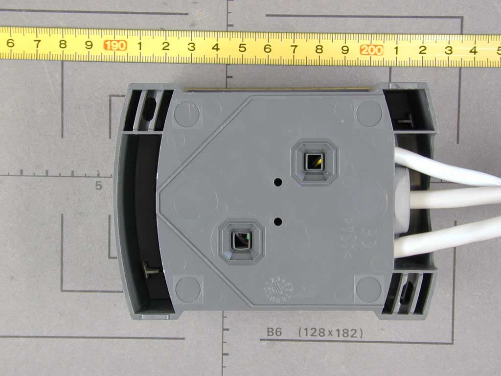
Click to zoom
Application Details
- Equipment Class
- DXT - Part 15 Low Power Transceiver, Rx Verified
- Date of Grant
- Dec 10, 2002
- Application Purpose
- Original Equipment
- Date of Application
- Dec 10, 2002
- Equipment Note
- Inductive Tag Reader
- Frequency Range
- 13.56000000 - 13.56000000
- Company
- Feig Electronic GmbH
- Country
- Germany
Documents & Files
Document Text
Text extracted from the exhibit documents filed with the FCC. Open a document above to read the original.
Users Manual
MONTAGE INSTALLATION preliminary public (B) 2002-09-13 M10701-1de-ID-B.doc OBID ® classic pro ID CPR.02-A (RS232 Interface) ID CPR.02-B (RS485 Interface) (deutsch / english) OBID ® classic pro MontageID CPR.02-x Seite 2 von 36FEIG ELECTRONIC GmbH D E U T S C H deutsche Version ab Seite 3 english version from page 20 E N G L I S H OBID ® classic pro MontageID CPR.02-x FEIG ELECTRONIC GmbHSeite 3 von 36 Hinweis Copyright 1999 - 2002 by FEIG ELECTRONIC GmbH Lange Straße 4 D-35781 Weilburg-Waldhausen Tel.: +49 6471 3109-0 http://www.feig.de Alle früheren Ausgaben verlieren mit dieser Ausgabe ihre Gültigkeit. Die Angaben in diesem Handbuch können ohne vorherige Ankündigung geändert werden. Weitergabe sowie Vervielfältigung dieses Dokuments, Verwertung und Mitteilung ihres Inhalts sind nicht ge- stattet, soweit nicht ausdrücklich zugestanden. Zuwiderhandlung verpflichtet zu Schadenersatz. Alle Rechte für den Fall der Patenterteilung oder Gebrauchsmuster-Eintragung vorbehalten. Die Zusammenstellung der Informationen in diesem Dokument erfolgt nach bestem Wissen und Gewissen. FEIG ELECTRONIC GmbH übernimmt keine Gewährleistung für die Richtigkeit und Vollständigkeit der An- gaben in diesem Dokument. Insbesondere kann FEIG ELECTRONIC GmbH nicht für Folgeschäden auf Grund fehlerhafter oder unvollständiger Angaben haftbar gemacht werden. Da sich Fehler, trotz aller Bemü- hungen nie vollständig vermeiden lassen, sind wir für Hinweise jederzeit dankbar. Die in diesem Dokument gemachten Installationsempfehlungen gehen von günstigsten Rahmenbedingungen aus. FEIG ELECTRONIC GmbH übernimmt keine Gewähr für die einwandfreie Funktion in systemfremden Umgebungen. FEIG ELECTRONIC GmbH übernimmt keine Gewährleistung dafür, dass die in diesem Dokument enthalten- den Informationen frei von fremden Schutzrechten sind. FEIG ELECTRONIC GmbH erteilt mit diesem Do- kument keine Lizenzen auf eigene oder fremde Patente oder andere Schutzrechte. OBID ® ist ein eingetragenes Warenzeichen der FEIG ELECTRONIC GmbH Allgemeine Hinweise zu diesem Dokument Das Zeichen „!“ weist auf Erweiterungen bzw. Änderungen gegenüber der Vorgängerversion hin. OBID ® classic pro MontageID CPR.02-x Seite 4 von 36FEIG ELECTRONIC GmbH D E U T S C H Inhalt 1.Sicherheits- und Warnhinweise5 2.Montage6 2.1Montage auf Unterputzdose....................................................................................... 7 2.2Montage mit Aufputzrahmen ID APR-A ..................................................................... 8 3.Leseranschluss9 3.1Jumper und Schalter ................................................................................................ 10 3.2Spannungsversorgung............................................................................................. 11 3.3Relais......................................................................................................................... 11 3.4Digitale Eingänge ..................................................................................................... 11 3.5RS232-Schnittstelle (ID CPR.02-A) .......................................................................... 11 3.6RS485-Schnittstelle (ID CPR.02-B) .......................................................................... 12 3.7Daten-/Taktschnittstelle ........................................................................................... 13 4.Inbetriebnahme14 4.1Adresseinstellung (Busbetrieb mit RS485-Schnittstelle) ...................................... 14 5.Technische Daten15 5.1Zulassung ................................................................................................................. 16 5.2Abmessungen Unterputzmontage........................................................................... 17 5.3Abmessungen mit ID APR-A bei Aufputzmontage ................................................. 18 6.Lieferumfang:19 6.1Optionales Zubehör.................................................................................................. 19 OBID ® classic pro MontageID CPR.02-x FEIG ELECTRONIC GmbHSeite 5 von 36 1. Sicherheits- und Warnhinweise • Das Gerät darf nur für den vom Hersteller vorgesehenen Zweck verwendet werden. • Die Bedienungsanleitung ist zugriffsfähig aufzubewahren und jedem Benutzer auszu- händigen. • Unzulässige Veränderungen und die Verwendung von Ersatzteilen und Zusatzeinrich- tungen, die nicht vom Hersteller des Gerätes verkauft oder empfohlen werden, können Brände, elektrische Schläge und Verletzungen verursachen. Solche Maßnahmen führen daher zu einem Ausschluss der Haftung und der Hersteller übernimmt keine Gewährlei- stung. • Für das Gerät gelten die Gewährleistungsbestimmungen des Herstellers in der zum Zeitpunkt des Kaufs gültigen Fassung. Für eine ungeeignete, falsche manuelle oder au- tomatische Einstellung von Parametern für ein Gerät bzw. ungeeignete Verwendung ei- nes Gerätes wird keine Haftung übernommen. • Reparaturen dürfen nur vom Hersteller durchgeführt werden. • Anschluss-, Inbetriebnahme-, Wartungs-, und sonstige Arbeiten am Gerät dürfen nur von Elektrofachkräften mit einschlägiger Ausbildung erfolgen. • Vor dem Öffnen des Gerätes ist stets die Versorgungsspannung abzuschalten und durch Nachmessen sicherzustellen, daß das Gerät spannungslos ist. Das Verlöschen einer Betriebsanzeige ist kein Indikator dafür, daß das Gerät vom Netz getrennt und spannungslos ist. • Alle Arbeiten am Gerät und dessen Aufstellung müssen in Übereinstimmung mit den nationalen elektrischen Bestimmungen und den örtlichen Vorschriften durchgeführt werden. • Beim Arbeiten an dem Gerät müssen die jeweils gültigen Sicherheitsvorschriften beach- tet werden. • Bei gewaltsamer Entfernung des Lesers kann die Steuerleitung (sofern das Relais be- nutzt wird) für die Tür/Torsteuerung kurzgeschlossen werden. Hierdurch ist ein unbe- fugtes Öffnen der/des Tür/Tores möglich. OBID ® classic pro MontageID CPR.02-x Seite 6 von 36FEIG ELECTRONIC GmbH D E U T S C H 2. Montage Der Leser ist für die Wan…
Text truncated - open the document above for the full version.
Cover Letter(s)
Request for Confidentiality 23 October 2002 PHOENIX TEST-LAB GmbH Kˆnigswinkel 10 D32825 Blomberg Germany RE: Certification Application FCC ID: PJMCPR02 Please be advised that the following information is to be held confidential on behalf of FEIG ELECTRONIC GmbH: • Schematics • Block Diagram • Technical Description • Parts Lists The application contains technical information which FEIG ELECTRONIC GmbH deems to be trade secrets and proprietary. If made public, the information might be used to the disadvantage of the applicant in the market place. Thank you for your attention to this matter.
External Photos
FCC ID: PJMCPR02 External Photos Page 1 of 2 FCC ID: PJMCPR02 External Photos Page 2 of 2
ID Label/Location Info
FCC-ID: PJMCPR02 This device complies with Part 15 of the FCC Rules, Operation is subject to the following two conditions: (1) this device may not cause harmful interference and (2) this device must accept any interference received, including interference that may cause undesired operation.
Internal Photos
FCC ID: PJMCPR02 Internal Photo s Page 1 of 3 FCC ID: PJMCPR02 Internal Photo s Page 2 of 3 FCC ID: PJMCPR02 Internal Photo s Page 3 of 3
Test Report
FCC-ID: Test Report No. 50602-20327 Page 1 of 27 Pages Straubing, 13 June 2002 T E S T - R E P O R T No. 50602-20327 for ID CPR.02 Inductive Tag Reader Applicant: FEIG ELECTRONIC GmbH Purpose of testing: To show compliance with FCC Code of Federal Regulations, CFR 47, Part 15, Subpart C, Section 15.225 Note: The test data of this report relate only to the individual item which has been tested. This report shall not be reproduced except in full extent without the written approval of the testing laboratory. FCC-ID: Test Report No. 50602-20327 Page 2 of 27 Pages Table of Contents 1. Administrative Data ............................................................................................. 3 2. Identification of Test Laboratory .......................................................................... 4 3. Summary of Test Results .................................................................................... 5 4. Operation Mode of EUT....................................................................................... 6 5. Configuration of EUT and Peripheral Devices ..................................................... 7 6. Measuring Methods ............................................................................................. 8 6.1. Field strength of in-band emissions (ß15.225 (a)) and unwanted emissions < 30 MHz (ß15.225 (b)) ............................................... 8 6.2. Frequency tolerance (ß15.225 (c))................................................................ 9 6.3. Unwanted Emission 30 MHz - 1 GHz (ß15.225 (b)) .................................... 11 7. Photographs of Test Setups .............................................................................. 13 7.1. Radiated Emissions 9 kHz ñ 30 MHz .............................................................. 13 7.2. Radiated Emissions 30 ñ 1000 MHz (anechoic chamber) ............................... 14 7.3. Radiated Emissions 30 ñ 1000 MHz (open area test site) ............................... 16 8. Equipment List................................................................................................... 18 9. Referenced Regulations .................................................................................... 20 10. List of Measurements ........................................................................................ 21 11. Test Results ...................................................................................................... 22 12. Charts taken during testing................................................................................ 27 FCC-ID: Test Report No. 50602-20327 Page 3 of 27 Pages 1. Administrative Data Equipment Under Test (EUT): ID CPR.02 Serial number(s): 0001 Type of equipment: Inductive Tag Reader Type of emission: 10K0A1D Parts/accessories: --- FCC-ID: Applicant: FEIG ELECTRONIC GmbH (full address) Lange Strasse 4 D-35781 Weilburg-Waldhausen Contract identification: Order no. EB201718 / 16483 Contact person: Mr. Bernhard Sch ̧fller Manufacturer: FEIG ELECTRONIC GmbH Receipt of EUT: May, 2002 Dates of test: June, 2002 Note: --- Responsible for testing: Thomas Eberl Responsible for test report: Thomas Eberl FCC-ID: Test Report No. 50602-20327 Page 4 of 27 Pages 2. Identification of Test Laboratory Test Laboratory: Senton GmbH EMI/EMC Test Center (full address): Aeussere Fruehlingstrasse 45 D-94315 Straubing Germany Contact person: Mr. Johann Roidt Communication: Telephone (+49) 0 94 21 / 55 22-0 Fax (+49) 0 94 21 / 55 22-99 eMail: [email protected] FCC registration number: 90926 Industry Canada file number: IC 3050 FCC-ID: Test Report No. 50602-20327 Page 5 of 27 Pages 3. Summary of Test Results The tested sample complies with the requirements for set forth in the The Code of Federal Regulations 47, Part 15, Subpart C, Section 15.225 of the Federal Communication Commission (FCC). Johann Roidt Thomas Eberl Technical Manager Test Engineer FCC-ID: Test Report No. 50602-20327 Page 6 of 27 Pages 4. Operation Mode of EUT Continuously reading a TAG Reading distance : 50 mm FCC-ID: Test Report No. 50602-20327 Page 7 of 27 Pages 5. Configuration of EUT and Peripheral Devices Configuration of cables of EUT Not applicable Configuration of peripheral devices connected to EUT All tests were performed with the EUT connected to a Fujitsu LiteLine Model 5033 Notebook computer via RS 232 interface. The EUT was powered by an external DC power supply. FCC-ID: Test Report No. 50602-20327 Page 8 of 27 Pages 6. Measuring Methods 6.1. Field strength of in-band emissions (ß15.225 (a)) and unwanted emissions < 30 MHz (ß15.225 (b)) Radiated emissions in the frequency range 9 kHz ñ 30 MHz will be measured initially at a distance of 3 meters. A prescan at 3 meter distance will be performed in a shielded room with the detector of the spectrum analyzer or EMI Receiver set to peak. Final measurement is then performed at 30 meter distance. In case the regulation requires testing at other distances, the result will be extrapolated. The extrapolation factor will be determined by making a second measurement at 10 meter distance. The provisions of 15.31 (d) apply. According to section 15.209 (d) final measurementis performed with the detector set to Quasi Peak except for the frequency bands 9 ñ 90 kHz and 110 ñ 490 kHz where average detector is employed. FCC-ID: Test Report No. 50602-20327 Page 9 of 27 Pages 6.2. Frequency tolerance (ß15.225 (c)) 6.2.1. Frequency stability vs. temperature The frequency stability vs. temperature was measured with a spectrum analyzer connected to the output of the transmitter power amplifier via probe antenna while EUT was operating in transmit mode using the assigned frequency. The trace mode of the spectrum analyzer was set to write with frequency count mode activated: RBW = 100 Hz, VBW = 100 Hz, span = 20 kHz, sweep = 1.5 s (auto mode) See figure 1 for the measurement setup. Test equipment used (see equipment list for details): 02, 18, 51, 54, 69, 70, 7…
Text truncated - open the document above for the full version.
Test Setup Photos
FCC-ID: Test Report No. 50602-20327 Page 13 of 27 Pages 7.Photographs of Test Setups 7.1. Radiated Emissions 9 kHz – 30 MHz FCC-ID: Test Report No. 50602-20327 Page 14 of 27 Pages 7.2. Radiated Emissions 30 – 1000 MHz (anechoic chamber) FCC-ID: Test Report No. 50602-20327 Page 15 of 27 Pages Radiated Emissions 30 – 1000 MHz (anechoic chamber) continued FCC-ID: Test Report No. 50602-20327 Page 16 of 27 Pages 7.3. Radiated Emissions 30 – 1000 MHz (open area test site) FCC-ID: Test Report No. 50602-20327 Page 17 of 27 Pages Radiated Emissions 30 – 1000 MHz (open area test site) continued
Contact Information
Applicant
Elmar Reichwein(Manager)
Technical Contact
Senton GmbHJohann Roidt
[email protected]+49 9421 55 22 13
Aeussere Fruehlingsstrasse 45 · Straubing · Germany
Non-Technical Contact
Senton GmbHJohann Roidt
[email protected]+49 9421 55 22 13
Test Firm
TUV SUD Product Service GmbH PS-EMC-STRRainer Heller
Technical Specifications
| # | Rule Parts | Frequency Range | Power Output | Tolerance |
|---|---|---|---|---|
| 1 | 15C | 13.56 MHz - 13.56 MHz | - | 0.0100000000 % |
Other Applications from Feig Electronic GmbH

PJMPRM103
Feb 25, 2026RFID Reader
Equipment Class
DXX - Part 15 Low Power Communication Device Transmitter
PJMMRM103
Jan 19, 2026RFID Reader
Equipment Class
DXX - Part 15 Low Power Communication Device TransmitterPJMTSTFSAMC
Dec 01, 2024Wireless Safety System for industrial doors - Mobile Unit
Equipment Class
DXX - Part 15 Low Power Communication Device Transmitter
PJMLRM5400
Jun 27, 2023RFID Reader
Equipment Class
DXX - Part 15 Low Power Communication Device Transmitter
PJMMRU102A
Jul 07, 2021RFID Reader
Equipment Class
DSS - Part 15 Spread Spectrum Transmitter