PJMCPR03Inductive Tag Reader
Feig Electronic GmbH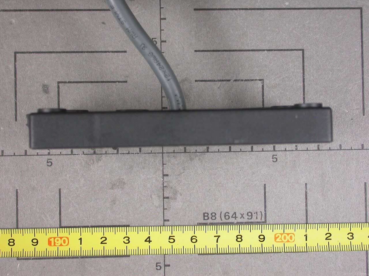
Click to zoom
Application Details
- Equipment Class
- DXT - Part 15 Low Power Transceiver, Rx Verified
- Date of Grant
- Feb 22, 2006
- Application Purpose
- Original Equipment
- Date of Application
- Feb 22, 2006
- Equipment Note
- Inductive Tag Reader
- Frequency Range
- 13.56000000 - 13.56000000
- Company
- Feig Electronic GmbH
- Country
- Germany
Documents & Files
Document Text
Text extracted from the exhibit documents filed with the FCC. Open a document above to read the original.
Users Manual
INSTALLATION Page 1 of 11 OBID ® classic-pro ID CPR.03-VP/AB-A Multitag Reader Data/Clock OBID ® classic-proInstallationID CPR.03-VP/AB-A FEIG ELECTRONIC GmbH Page 2 of 11 Note © Copyright 2006 by FEIG ELECTRONIC GmbH Lange Strasse 4 D-35781 Weilburg-Waldhausen Tel.: +49 6471 3109-0 http://www.feig.de With the edition of this document, all previous editions become void. Indications made in this manual may be changed without previous notice. Copying of this document, and giving it to others and the use or communication of the contents thereof are forbidden without express authority. Offenders are liable to the payment of damages. All rights are reserved in the event of the grant of a patent or the registration of a utility model or design. Composition of the information in this manual has been done to the best of our knowledge. FEIG ELECTRONIC GmbH does not guarantee the correctness and completeness of the details given in this manual and may not be held liable for damages ensuing from incorrect or incomplete information. Since, despite all our efforts, errors may not be completely avoided, we are always grateful for your useful tips. The installation instructions given in this manual are based on advantageous boundary conditions. FEIG ELECTRONIC GmbH does not give any guarantee promise for perfect function in cross environments. FEIG ELECTRONIC GmbH assumes no responsibility for the use of any information contained in this manual and makes no representation that they free of patent infringement. FEIG ELECTRONIC GmbH does not convey any license under its patent rights nor the rights of others. OBID ® and OBID i-scan ® is a registered trademark of FEIG ELECTRONIC GmbH. my-d ® is a registered trademark of Technologies AG I-CODE ® and mifare ® is a registered trademark of Philips Electronics N.V. Tag-it TM is a registered trademark of Texas Instruments Incorporated OBID ® classic-proInstallationID CPR.03-VP/AB-A FEIG ELECTRONIC GmbH Page 3 of 11 Contents 1Safety Instructions / Warning - Read before start-up !4 2Introduction4 3Technical Specifications5 Dimensions ..................................................................................................................................6 3.2Approval .........................................................................................................................6 4Installation7 4.1Mounting ........................................................................................................................7 4.2Connection.....................................................................................................................8 4.3Configuration .................................................................................................................9 4.3.1 Default Configuration....................................................................................................9 4.3.2 Reloading the configuration.........................................................................................9 5Normal Operating Mode10 5.1Digital Inputs................................................................................................................10 5.2Data-/Clock Interface...................................................................................................11 5.3Asynchronous Interface: RS232-TTL ........................................................................11 6System Delivery Contents11 OBID ® classic-proInstallationID CPR.03-VP/AB-A FEIG ELECTRONIC GmbH Page 4 of 11 1 Safety Instructions / Warning - Read before start-up ! • The device may only be used for the intended purpose designed by for the manufacturer. • The operation manual should be conveniently kept available at all times for each user. • Unauthorized changes and the use of spare parts and additional devices which have not been sold or recommended by the manufacturer may cause fire, electric shocks or injuries. Such unauthorized measures shall exclude any liability by the manufacturer. • The liability-prescriptions of the manufacturer in the issue valid at the time of purchase are valid for the device. The manufacturer shall not be held legally responsible for inaccuracies, errors, or omissions in the manual or automatically set parameters for a device or for an incorrect application of a device. • Repairs may only be executed by the manufacturer. • Installation, operation, and maintenance procedures should only be carried out by qualified personnel. • Use of the device and its installation must be in accordance with national legal requirements and local electrical codes . • When working on devices the valid safety regulations must be observed. • Special advice for carriers of cardiac pacemakers: Although this device doesn't exceed the valid limits for electromagnetic fields you should keep a minimum distance of 25 cm between the device and your cardiac pace- maker and not stay in an immediate proximity of the device respective the antenna for some time. 2 Introduction The Multitag-Reader ID CPR.03-VP/AB-A is designed for access control and time-recording sys- tems. Via the configurable data-/clock interface it can connected easily with usual access control and time-recording controllers. The ID CPR.03-VP/AB-A could read the serial-no. (UID) of the most common 13,56 MHz Trans- ponder according ISO 14443 type A, ISO 14443 type B and ISO 15693. The ID CPR.03-VP/AB-A is designed to be wall-mounted onto flat and non-conductive walls with or without a flush-mounting box. The data-/clock interface could configured like Wiegand- or magnetic stripe format (ISO7811-2, 5 Bit). The configuration could changed while installation with a ConfigCard transponder. This ConfigCard could prepared comfortable before Installation with a separate tool. OBID ® classic-proInstallationID CPR.03-VP/AB-A FEIG ELECTRONIC GmbH Page 5 of 11 3 Technical Specifications HousingPlastic ABS (sealed-in electronics) Colorgray - beige Weightapprox. 170 g Protecti…
Text truncated - open the document above for the full version.
Cover Letter(s)
FEIG ELECTRONIC GmbH - Lange Straße 4 - D-35781 Weilburg-Waldhausen account details: Kreissparkasse Weilburg (Bank sorting code No. 511 519 19) Account-No. 100 451 012 IBAN: DE 38511519190100451012 Dresdner Bank Limburg (Bank sorting code No. 513 800 40) Account-No. 9 367 354 00 IBAN: DE 60 5138 0040 0936 7354 00 Managing Director: Dipl.-Ing. Wolfgang Feig Place of Jurisdiction: Limburg HRB 3178 Sales tax-IdNo. DE 811 460 661 VEK Traffic Detectors TST Control technology OBID ® Object identification your signdate of your messageour signyour correspondency partnerdate CFFiedler19.04.2005 To Whom It May Concern: Please be advised that FEIG ELECTRONIC GmbH authorizes Senton GmbH to act on our behalf, until otherwise notified, for applications submitted to PHOENIX TEST-LAB GmbH (PTL). We certify that we are not subject to denial of federal benefits, that includes FCC benefits, pursuant to Section 5301 of the Anti-Drug Abuse ACT of 1988, U.S.C.862. Further, no party, as defined in 47 CFR 1.2002 (b), to the application is subject to denial of federal benefits, that includes FCC benefits. Thank you for your attention to this matter. FEIG ELECTRONIC ______________________________________ Dipl.-Ing. Carsten Fiedler R&D PHOENIX TEST-LAB GmbH Product Certification Königswinkel 10 D 32825 Blomberg FEIG ELECTRONIC GmbH Lange Straße 4 D-35781 Weilburg-Waldhausen Phone:+49 6471/31 09-0 Fax:+49 6471/31 09-99
Cover Letter(s)
Request for Confidentiality in accordance with 47 CFR 0.459 Date: 22 February 2006 PHOENIX TEST-LAB GmbH Kˆnigswinkel 10 D32825 Blomberg Germany RE: Certification Application FCC ID: PJMCPR03 Please be advised that the following information is to be held confidential on behalf of FEIG ELECTRONIC GmbH: • Schematics • Parts Lists • Block Diagram • Technical Description The application contains technical information which FEIG ELECTRONIC GmbH deems to be trade secrets and proprietary. If made public, the information might be used to the disadvantage of the applicant in the market place. Thank you for your attention to this matter.
External Photos
FCC ID PJMCPR03 FCC ID PJMCPR03 FCC ID PJMCPR03 FCC ID PJMCPR03 FCC ID PJMCPR03 FCC ID PJMCPR03 FCC ID PJMCPR03 FCC ID PJMCPR03 FCC ID PJMCPR03 FCC ID PJMCPR03 FCC ID PJMCPR03 FCC ID PJMCPR03
ID Label/Location Info
This device complies with Part 15 of the FCC rules. Operation is subject to the following two conditions: (1) this device may not cause harmful interference and (2) this device must accept an y interference received, including interference that may cause undesired operation.
Test Report
Senton GmbH Aeussere Fruehlingstrasse 45 D-94315 Straubing Note: The test data of this report is related only to the individual item which has been tested. This report shall not be reproduced except in full extent without the written approval of the testing laboratory. Test Report No. 50602 - 060113 (Edition 1) Page 1 of 51 Pages Straubing, 14 February 2006 T E S T - R E P O R T No. 50602 - 060113 (Edition 1) for ID CPR.03-VP/AB Inductive Tag Reader Applicant: FEIG ELECTRONIC GmbH Test Specifications: FCC Code of Federal Regulations, CFR 47, Part 15, Sections 15.205, 15.207, 15.215 and 15.225 Industry Canada Radio Standards Specifications RSS-Gen Issue 1, Section 7.2.2 and RSS-210 Issue 6, Sections 2.2, 2.6, A2.6 (Category I Equipment) Senton GmbH Aeussere Fruehlingstrasse 45 D-94315 Straubing Test Report No. 50602 - 060113 (Edition 1) Page 2 of 51 Pages Table of Contents 1 Description of the Equipment Under Test (EUT) ........................................................ 3 2 Administrative Data..................................................................................................... 4 3 Identification of the Test Laboratory ........................................................................... 5 4 Summary .................................................................................................................... 6 5 Operation Mode and Configuration of EUT................................................................. 7 6 Measurement Procedures........................................................................................... 8 6.1 Bandwidth Measurements .................................................................................... 8 6.2 Conducted AC Powerline Emission ...................................................................... 9 6.3 Radiated Emission Measurement 9 kHz to 30 MHz ........................................... 11 6.4 Radiated Emission in Fully or Semi Anechoic Room.......................................... 13 6.5 Radiated Emission at Open Field Test Site........................................................ 15 6.6 Carrier Frequency Stability ................................................................................. 16 7 Photographs Taken During Testing .......................................................................... 18 8 Test Results .............................................................................................................. 24 8.1 Occupied Bandwidth........................................................................................... 26 8.2 Bandwidth of the Emission ................................................................................. 31 8.3 Designation of Emissions ................................................................................... 33 8.4 Spectrum Mask................................................................................................... 37 8.5 Radiated Emission Measurement 9 kHz to 30 MHz .......................................... 40 8.6 Radiated Emission Measurement 30 MHz to 1 GHz ......................................... 43 8.7 Carrier Frequency Stability ................................................................................. 46 8.8 Exposure of Humans to RF Fields...................................................................... 49 9 Referenced Regulations ........................................................................................... 50 10 Charts taken during testing ....................................................................................... 51 Senton GmbH Aeussere Fruehlingstrasse 45 D-94315 Straubing Test Report No. 50602 - 060113 (Edition 1) Page 3 of 51 Pages 1 Description of the Equipment Under Test (EUT) General data of EUT Type designation 1 : ID CPR.03-VP/AB Parts 2 : Serial number(s): 01 Manufacturer: FEIG ELECTRONIC GmbH Type of equipment: Inductive Tag Reader Version: FCC ID: PJMCPR03 Additional parts/accessories: Technical data of EUT Application frequency range: 13.553 - 13.567 MHz Frequency range: Operating frequency: 13.56 MHz Type of modulation: ASK Pulse train: --- Pulse width: --- Number of RF-channels: 1 Channel spacing: --- Designation of emissions 3 : 10K0A1D Type of antenna: Integrated Loop Coil Size/length of antenna: 65 x 100 mm Connection of antenna: detachable not detachable Type of power supply: DC supply Specifications for power supply: nominal voltage: 12.0 V minimum voltage: 9.0 V maximum voltage: 15.0 V 1 Type designation of the system if EUT consists of more than one part. 2 Type designations of the parts of the system, if applicable. 3 Also known as "Class of Emission". Senton GmbH Aeussere Fruehlingstrasse 45 D-94315 Straubing Test Report No. 50602 - 060113 (Edition 1) Page 4 of 51 Pages 2 Administrative Data Application details Applicant (full address): FEIG ELECTRONIC GmbH Lange Strafle 4 D-35781 Weilburg-Waldhausen Contact person: Mr. Bernhard Sch ̧fller Contract identification: EB203749 / 16483 Receipt of EUT: 27 April 2005 Date(s) of test: April - June 2005 Note(s): --- Report details Report number: 50602 - 060113 Edition: 1 Issue date: 14 February 2006 Senton GmbH Aeussere Fruehlingstrasse 45 D-94315 Straubing Test Report No. 50602 - 060113 (Edition 1) Page 5 of 51 Pages 3 Identification of the Test Laboratory Details of the Test Laboratory Company name: Senton GmbH EMI/EMC Test Center Address: Aeussere Fruehlingstrasse 45 D-94315 Straubing Germany Laboratory accreditation: DAR-Registration No. DAT-P-171/94-02 FCC test site registration number 90926 Industry Canada test site registration: IC 3050 Contact person: Mr. Johann Roidt Phone: (+49) (0)9421 5522-0 Fax: (+49) (0)9421 5522-99 Senton GmbH Aeussere Fruehlingstrasse 45 D-94315 Straubing Test Report No. 50602 - 060113 (Edition 1) Page 6 of 51 Pages 4 Summary Summary of test results The tested sample complies with the requirements set forth in the Code of Federal Regulations CFR 47, Part 15, Sections 15.205…
Text truncated - open the document above for the full version.
Test Setup Photos
Senton GmbH Aeussere Fruehlingstrasse 45 D-94315 Straubing Test Report No. 50602 - 060113 (Edition 1) Page 19 of 51 Pages Test setup for conducted AC powerline emission measurement Senton GmbH Aeussere Fruehlingstrasse 45 D-94315 Straubing Test Report No. 50602 - 060113 (Edition 1) Page 20 of 51 Pages Test setup for radiated emission measurement 9 kHz ñ 30 MHz Senton GmbH Aeussere Fruehlingstrasse 45 D-94315 Straubing Test Report No. 50602 - 060113 (Edition 1) Page 21 of 51 Pages Test setup for radiated emission measurement (fully anechoic room) Senton GmbH Aeussere Fruehlingstrasse 45 D-94315 Straubing Test Report No. 50602 - 060113 (Edition 1) Page 22 of 51 Pages Test setup for radiated emission measurement (open field test site) Senton GmbH Aeussere Fruehlingstrasse 45 D-94315 Straubing Test Report No. 50602 - 060113 (Edition 1) Page 23 of 51 Pages Test setup for radiated emission measurement (open field test site) - continued -
Contact Information
Applicant
Elmar Reichwein(Manager)
Technical Contact
Senton GmbHJohann Roidt
[email protected]+49 9421 55220
Aeussere Fruehlingstrasse 45 · Straubing · Germany
Test Firm
TUV SUD Product Service GmbH PS-EMC-STRRainer Heller
Technical Specifications
| # | Rule Parts | Frequency Range | Power Output | Tolerance |
|---|---|---|---|---|
| 1 | 15C | 13.56 MHz - 13.56 MHz | - | 0.0100000000 % |
Other Applications from Feig Electronic GmbH

PJMPRM103
Feb 25, 2026RFID Reader
Equipment Class
DXX - Part 15 Low Power Communication Device Transmitter
PJMMRM103
Jan 19, 2026RFID Reader
Equipment Class
DXX - Part 15 Low Power Communication Device TransmitterPJMTSTFSAMC
Dec 01, 2024Wireless Safety System for industrial doors - Mobile Unit
Equipment Class
DXX - Part 15 Low Power Communication Device Transmitter
PJMLRM5400
Jun 27, 2023RFID Reader
Equipment Class
DXX - Part 15 Low Power Communication Device Transmitter
PJMMRU102A
Jul 07, 2021RFID Reader
Equipment Class
DSS - Part 15 Spread Spectrum Transmitter