PJMCPR04Inductive Tag Reader
Feig Electronic GmbH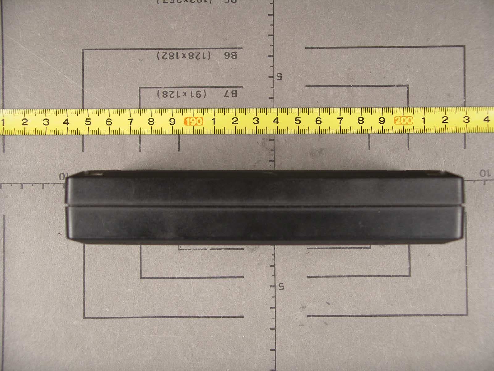
Click to zoom
Application Details
- Equipment Class
- DXT - Part 15 Low Power Transceiver, Rx Verified
- Date of Grant
- Jan 30, 2007
- Application Purpose
- Original Equipment
- Date of Application
- Jan 30, 2007
- Equipment Note
- Inductive Tag Reader
- Frequency Range
- 13.56000000 - 13.56000000
- Company
- Feig Electronic GmbH
- Country
- Germany
Documents & Files
Document Text
Text extracted from the exhibit documents filed with the FCC. Open a document above to read the original.
Users Manual
MONTAGE INSTALLATION ID CPR04-Manual.DOC / 2006-12-21 OBID ® classic-pro ID CPR.04.P/AB-USB Anschluss und InbetriebnahmeInstallation and starting up Vielen Dank, dass Sie sich für den Kauf des ID CPR.04.P/AB-USB entschieden haben. Der ID CPR.04.P/AB-USB ist als Desktop-Gerät für den Office Einsatz konzipiert. Er sich für den berüh- rungslosen Datenaustausch mit gängigen ISO 14443 Transpondern ausgelegt und eignet sich für eine Vielzahl von Applikationen wie beispielsweise ePassport, eVisa, ePurse oder Ticketing. Der Anschluss an einem Computer oder sonstiges Gerät erfolgt über die USB Schnittstelle. Thank you for deciding to purchase the ID CPR.04.P/AB-USB The ID CPR.04.P/AB-USB designed as a desktop device for office applications. It is designed for con- tactless data exchange with common ISO 144443 Transponder and is suited for various applications like ePassport, eVisa, ePurse or ticketing. The connection to a computer or other equipment is carried out via the USB interface Fig 1.: ID CPR.04.P/AB-USB n USB Buchse o LED grün p LED blau q Lesefeld n USB Connector o LED green p LED blue q Detection field Bitte entnehmen Sie weitere Informationen zum Betrieb des Geräts der beiliegenden CD-ROM. Please take further information's about the opera- tion of the device form attached CD-ROM. 1 2 3 4 OBID ® classic-proMONTAGE / INSTALLATIONID CPR.04.P/AB-USB FEIG ELECTRONIC GmbHID CPR04-Manual.DOC Sicherheits- und WarnhinweiseSafety Instructions • Das Gerät darf nur für den vom Hersteller vorgesehenen Zweck verwendet werden. • Die Bedienungsanleitung ist zugriffsfähig aufzubewahren und jedem Benutzer aus- zuhändigen. • Unzulässige Veränderungen und die Ver- wendung von Ersatzteilen und Zusatzein- richtungen, die nicht vom Hersteller des Gerätes verkauft oder empfohlen werden, können Brände, elektrische Schläge und Verletzungen verursachen. Solche Maß- nahmen führen daher zu einem Ausschluss der Haftung und der Hersteller übernimmt keine Gewährleistung. • Für das Gerät gelten die Gewährleistungs- bestimmungen des Herstellers in der zum Zeitpunkt des Kaufs gültigen Fassung. Für eine ungeeignete, falsche manuelle oder automatische Einstellung von Parametern für ein Gerät bzw. ungeeignete Verwendung eines Gerätes wird keine Haftung übernommen. • Reparaturen dürfen nur vom Hersteller durch- geführt werden. • Anschluss-, Inbetriebnahme-, Wartungs-, und sonstige Arbeiten am Gerät dürfen nur von Fachkräften mit einschlägiger Ausbildung erfolgen. • Alle Arbeiten am Gerät und dessen Aufstellung müssen in Übereinstimmung mit den nationalen elektrischen Bestimmungen und den örtlichen Vorschriften durchgeführt werden. • Bei Arbeiten an dem Gerät müssen die jeweils gültigen Sicherheitsvorschriften beachtet werden. • Besonderer Hinweis für Träger von Herzschrittmachern: Obwohl dieses Gerät die zulässigen Grenz- werte für elektromagnetische Felder nicht überschreitet, sollten Sie einen Mindestab- stand von 25 cm zwischen dem Gerät und Ihrem Herzschrittmacher einhalten und sich nicht für längere Zeit in unmittelbarer Nähe des Geräts bzw. der Antenne aufhalten. • The device may only be used for the intended purpose designed by for the manufacturer. • The operation manual should be conveniently kept available at all times for each user. • Unauthorized changes and the use of spare parts and additional devices which have not been sold or recommended by the manufacturer may cause fire, electric shocks or injuries. Such unauthorized measures shall exclude any liability by the manufacturer. • The liability-prescriptions of the manufacturer in the issue valid at the time of purchase are valid for the device. The manufacturer shall not be held legally responsible for inaccuracies, errors, or omissions in the manual or automatically set parameters for a device or for an incorrect application of a device. • Repairs may only be executed by the manufacturer. • Installation, operation, and maintenance procedures should only be carried out by qualified personnel. • Use of the device and its installation must be in accordance with national legal requirements and local electrical codes . • When working on devices the valid safety regulations must be observed. • Special advice for carriers of cardiac pacemakers: Although this device doesn't exceed the valid limits for electromagnetic fields you should keep a minimum distance of 25 cm between the device and your cardiac pacemaker and not stay in an immediate proximity of the de- vice respective the antenna for some time. OBID ® classic-proMONTAGE / INSTALLATIONID CPR.04.P/AB-USB FEIG ELECTRONIC GmbHID CPR04-Manual.DOC LieferumfangScope of Delivery • ID CPR.04.P/AB-USB Reader • CD-ROM mit OBID ® USB-Treiber • Montageanleitung • ID CPR.04.P/AB-USB Reader • CD-ROM with OBID ® USB-Driver • Installation Manual AnschlussConnection Die Verbindung zu einem PC und die Spannungs- versorgung erfolgt über die USB Buchse n, mit ei- nem Standard USB 2.0 Kabel mit A-B Steckern. • Die USB Schnittstelle muss einen Strom von 500 mA liefern können (High Powered Interface)! • USB Kabel mit max. 2,5 m Länge verwenden! Der Reader muss bei der Erstinbetriebnahme am Betriebssystem des Computers angemeldet werden. Details entnehmen Sie bitte der Anleitung „N51000- #de-ID-B: Installation des OBID ® USB-Treibers“. The connection with a PC and the power supply takes place through the USB connector n via a standard USB 2.0 cable with A-B connectors. • The USB-interface must support a current of 500 mA (High Powered Interface)! • Use only USB cable with max. 2,5 m length! If the reader is used for the first time, it must be reg- istered in the operating system of the computer. For this the instruction " N51000-#de-ID-B: Installation of the OBID ® USB driver" can be used. BetriebOperating Die grüne und blaue LED signalisieren Betriebszu- stände des ID CPR.04.P/AB-USB. Nach dem Einschalten oder nach einem Reset blinken die grüne und blaue LED für ca. 2 Sek. gleichzeitig. In dieser Zeit sollte kein Transpon- der au…
Text truncated - open the document above for the full version.
Cover Letter(s)
Federal Communications Commission 445 12 th Street SW Washington, DC 20554 USA Request for Confidentiality in accordance with CFR 0.457 and 0.459 29 January 2007 EMCCert DR. RAŠEK - Certification Institute - Boelwiese 5 D-91320 Ebermannstadt RE: Certification Application FCC ID: PJMCPR04 Please be advised that the following information is to be held confidential on behalf of FEIG ELECTRONIC GmbH: • Schematics • Parts List • Block Diagram • Technical Description The application contains technical information which FEIG ELECTRONIC GmbH deems to be trade secrets and proprietary. If made public, the information might be used to the disadvantage of the applicant in the market place. Thank you for your attention to this matter.
External Photos
FCC ID PJMCPR04 FCC ID PJMCPR04 FCC ID PJMCPR04 FCC ID PJMCPR04 FCC ID PJMCPR04 FCC ID PJMCPR04
ID Label/Location Info
FCC ID PJMCPR04 FCC ID PJMCPR04
Internal Photos
FCC ID PJMCPR04 FCC ID PJMCPR04 FCC ID PJMCPR04 FCC ID PJMCPR04 FCC ID PJMCPR04
Test Report
Senton GmbH Aeussere Fruehlingstrasse 45 D-94315 Straubing Note: The test data of this report is related only to the individual item which has been tested. This report shall not be reproduced except in full extent without the written approval of the testing laboratory. Test Report No. 50602-060877 (Edition 1) Page 1 of 60 Pages Straubing, 15 December 2006 T E S T - R E P O R T No. 50602-060877 (Edition 1) for ID CPR.04 Inductive Tag Reader Applicant: FEIG ELECTRONIC GmbH Test Specifications: FCC Code of Federal Regulations, CFR 47, Part 15, Sections 15.205, 15.207, 15.215 and 15.225 Industry Canada Radio Standards Specifications RSS-Gen Issue 1, Section 7.2.2 and RSS-210 Issue 6, Sections 2.2, 2.6, A2.6 (Category I Equipment) Senton GmbH Aeussere Fruehlingstrasse 45 D-94315 Straubing Test Report No. 50602-060877 (Edition 1) Page 2 of 60 Pages Table of Contents 1 Description of the Equipment Under Test (EUT) ........................................................ 3 2 Administrative Data..................................................................................................... 4 3 Identification of the Test Laboratory ........................................................................... 5 4 Summary .................................................................................................................... 6 5 Operation Mode and Configuration of EUT................................................................. 7 6 Measurement Procedures........................................................................................... 8 6.1 Bandwidth Measurements .................................................................................... 8 6.2 Conducted AC Powerline Emission ...................................................................... 9 6.3 Radiated Emission Measurement 9 kHz to 30 MHz ........................................... 11 6.4 Radiated Emission in Fully or Semi Anechoic Room.......................................... 13 6.5 Radiated Emission at Open Field Test Site........................................................ 15 6.6 Carrier Frequency Stability ................................................................................. 16 7 Photographs Taken During Testing .......................................................................... 18 8 Test Results .............................................................................................................. 25 8.1 Occupied Bandwidth........................................................................................... 27 8.2 Bandwidth of the Emission ................................................................................. 31 8.3 Designation of Emissions ................................................................................... 33 8.4 Restricted Bands of Operation ........................................................................... 34 8.5 Conducted Powerline Emission Measurement 150 kHz to 30 MHz................... 35 8.6 Spectrum Mask................................................................................................... 47 8.7 Radiated Emission Measurement 9 kHz to 30 MHz .......................................... 49 8.8 Radiated Emission Measurement 30 MHz to 1 GHz ......................................... 52 8.9 Carrier Frequency Stability ................................................................................. 54 8.10 Exposure of Humans to RF Fields...................................................................... 57 9 Referenced Regulations ........................................................................................... 59 10 Charts taken during testing ....................................................................................... 60 Senton GmbH Aeussere Fruehlingstrasse 45 D-94315 Straubing Test Report No. 50602-060877 (Edition 1) Page 3 of 60 Pages 1 Description of the Equipment Under Test (EUT) General data of EUT Type designation 1 : ID CPR.04 Parts 2 : Serial number(s): 0001 Manufacturer: FEIG ELECTRONIC GmbH Type of equipment: Inductive Tag Reader Version: As delivered FCC ID: Additional parts/accessories: Technical data of EUT Application frequency range: 13.553 - 13.567 MHz Frequency range: 13.56 MHz Operating frequency: 13.56 MHz Type of modulation: ASK Pulse train: --- Pulse width: --- Number of RF-channels: 1 Channel spacing: Not applicable Designation of emissions 3 : 1M70A1D Type of antenna: Integrated loop on printed board Size/length of antenna: Connection of antenna: detachable not detachable Type of power supply: DC supply over USB Specifications for power supply: nominal voltage: 5.00 V minimum voltage: 4.25 V maximum voltage: 5.75 V 1 Type designation of the system if EUT consists of more than one part. 2 Type designations of the parts of the system, if applicable. 3 Also known as "Class of Emission". Senton GmbH Aeussere Fruehlingstrasse 45 D-94315 Straubing Test Report No. 50602-060877 (Edition 1) Page 4 of 60 Pages 2 Administrative Data Application details Applicant (full address): FEIG ELECTRONIC GmbH Lange Straße 4 35781 Weilburg-Waldhausen Germany Contact person: Mr. Bernhard Schüßler Contract identification: Order No. EB204251 / 16483 (05 October 2006) Receipt of EUT: 10 October 2006 29 November 2006 Date(s) of test: October - December 2006 Note(s): Report details Report number: 50602-060877 Edition: 1 Issue date: 15 December 2006 Senton GmbH Aeussere Fruehlingstrasse 45 D-94315 Straubing Test Report No. 50602-060877 (Edition 1) Page 5 of 60 Pages 3 Identification of the Test Laboratory Details of the Test Laboratory Company name: Senton GmbH EMI/EMC Test Center Address: Aeussere Fruehlingstrasse 45 D-94315 Straubing Germany Laboratory accreditation: DAR-Registration No. DAT-P-171/94-02 FCC test site registration number 90926 Industry Canada test site registration: IC 3050 Contact person: Mr. Johann Roidt Phone: (+49) (0)9421 5522-0 Fax: (+49) (0)9421 5522-99 Senton GmbH Aeusser…
Text truncated - open the document above for the full version.
Test Setup Photos
Senton GmbH Aeussere Fruehlingstrasse 45 D-94315 Straubing Test Report No. 50602-060877 (Edition 1) Page 19 of 60 Pages Test setup for conducted AC powerline emission measurement Senton GmbH Aeussere Fruehlingstrasse 45 D-94315 Straubing Test Report No. 50602-060877 (Edition 1) Page 20 of 60 Pages Test setup for radiated emission measurement 9 kHz – 30 MHz Senton GmbH Aeussere Fruehlingstrasse 45 D-94315 Straubing Test Report No. 50602-060877 (Edition 1) Page 21 of 60 Pages Test setup for radiated emission measurement 9 kHz – 30 MHz - continued - Senton GmbH Aeussere Fruehlingstrasse 45 D-94315 Straubing Test Report No. 50602-060877 (Edition 1) Page 22 of 60 Pages Test setup for radiated emission measurement (fully anechoic room) Senton GmbH Aeussere Fruehlingstrasse 45 D-94315 Straubing Test Report No. 50602-060877 (Edition 1) Page 23 of 60 Pages Test setup for radiated emission measurement (open field test site) Senton GmbH Aeussere Fruehlingstrasse 45 D-94315 Straubing Test Report No. 50602-060877 (Edition 1) Page 24 of 60 Pages Test setup for radiated emission measurement (open field test site) - continued -
Contact Information
Applicant
Elmar Reichwein(Manager)
Test Firm
TUV SUD Product Service GmbH PS-EMC-STRRainer Heller
Technical Specifications
| # | Rule Parts | Frequency Range | Power Output |
|---|---|---|---|
| 1 | 15C | 13.56 MHz - 13.56 MHz | - |
Other Applications from Feig Electronic GmbH

PJMPRM103
Feb 25, 2026RFID Reader
Equipment Class
DXX - Part 15 Low Power Communication Device Transmitter
PJMMRM103
Jan 19, 2026RFID Reader
Equipment Class
DXX - Part 15 Low Power Communication Device TransmitterPJMTSTFSAMC
Dec 01, 2024Wireless Safety System for industrial doors - Mobile Unit
Equipment Class
DXX - Part 15 Low Power Communication Device Transmitter
PJMLRM5400
Jun 27, 2023RFID Reader
Equipment Class
DXX - Part 15 Low Power Communication Device Transmitter
PJMMRU102A
Jul 07, 2021RFID Reader
Equipment Class
DSS - Part 15 Spread Spectrum Transmitter