PJMCPRM02Inductive Tag Reader
Feig Electronic GmbH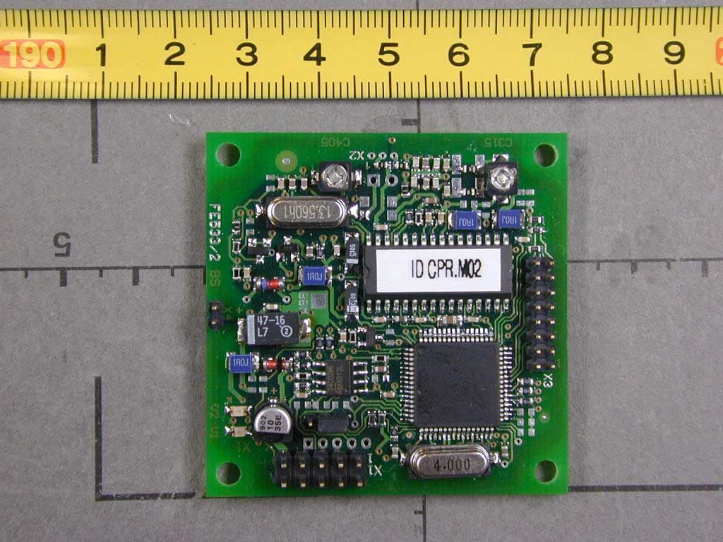
Click to zoom
Application Details
- Equipment Class
- DXT - Part 15 Low Power Transceiver, Rx Verified
- Date of Grant
- Feb 06, 2003
- Application Purpose
- Original Equipment
- Date of Application
- Feb 06, 2003
- Equipment Note
- Inductive Tag Reader
- Frequency Range
- 13.56000000 - 13.56000000
- Company
- Feig Electronic GmbH
- Country
- Germany
Documents & Files
Document Text
Text extracted from the exhibit documents filed with the FCC. Open a document above to read the original.
Users Manual
MONTAGE INSTALLATION final public (B) 2003-02-11 M21001-0de-ID-B.doc OBID ® classic-pro ID CPR.M02 (deutsch / english) OBID ® classic-proMontageID CPR.M02 FEIG ELECTRONIC GmbHSeite 2 von 39M21001-0de-ID-B.doc D E U T S C H OBID ® classic-proMontageID CPR.M02 FEIG ELECTRONIC GmbHSeite 3 von 39M21001-0de-ID-B.doc D E U T S C H deutsche Version ab Seite 4 english version from page 22 E N G L I S H OBID ® classic-proMontageID CPR.M02 FEIG ELECTRONIC GmbHSeite 4 von 39M21001-0de-ID-B.doc D E U T S C H Hinweis Copyright 2002 by FEIG ELECTRONIC GmbH Lange Straße 4 D-35781 Weilburg-Waldhausen Tel.: +49 6471 3109-0 http://www.feig.de Ausgabe: er/03/02/11 - m21001-0de-id-b.doc Alle früheren Ausgaben verlieren mit dieser Ausgabe ihre Gültigkeit. Die Angaben in diesem Handbuch können ohne vorherige Ankündigung geändert werden. Weitergabe sowie Vervielfältigung dieses Dokuments, Verwertung und Mitteilung ihres Inhalts sind nicht gestattet, soweit nicht ausdrücklich zugestanden. Zuwiderhandlung verpflichtet zu Schadenersatz. Alle Rechte für den Fall der Patenterteilung oder Gebrauchsmuster-Eintragung vorbehalten. Die Zusammenstellung der Informationen in diesem Dokument erfolgt nach bestem Wissen und Gewissen. FEIG ELECTRONIC GmbH übernimmt keine Gewährleistung für die Richtigkeit und Vollständigkeit der An- gaben in diesem Dokument. Insbesondere kann FEIG ELECTRONIC GmbH nicht für Folgeschäden auf Grund fehlerhafter oder unvollständiger Angaben haftbar gemacht werden. Da sich Fehler, trotz aller Bemü- hungen nie vollständig vermeiden lassen, sind wir für Hinweise jederzeit dankbar. Die in diesem Dokument gemachten Installationsempfehlungen gehen von günstigsten Rahmenbedingun- gen aus. FEIG ELECTRONIC GmbH übernimmt keine Gewähr für die einwandfreie Funktion in systemfrem- den Umgebungen. FEIG ELECTRONIC GmbH übernimmt keine Gewährleistung dafür, dass die in diesem Dokument enthal- tenden Informationen frei von fremden Schutzrechten sind. FEIG ELECTRONIC GmbH erteilt mit diesem Dokument keine Lizenzen auf eigene oder fremde Patente oder andere Schutzrechte. OBID ® ist ein eingetragenes Warenzeichen der FEIG ELECTRONIC GmbH OBID ® classic-proMontageID CPR.M02 FEIG ELECTRONIC GmbHSeite 5 von 39M21001-0de-ID-B.doc D E U T S C H Inhalt 1. Sicherheits- und Warnhinweise - vor Inbetriebnahme unbedingt lesen6 2. Leistungsmerkmale des Readermoduls ID CPR.M027 2.1. Leistungsmerkmale.......................................................................................................... 7 2.2. Verfügbare Modultypen....................................................................................................7 2.3. Lieferumfang..................................................................................................................... 7 3. Montage und Anschluss8 3.1. Abmessungen................................................................................................................... 8 3.2. Anschluss ......................................................................................................................... 9 3.2.1. Spannungsversorgung .............................................................................................. 10 3.2.2. RS232-Schnittstelle................................................................................................... 11 3.2.3. Daten-/Taktschnittstelle............................................................................................. 12 3.2.4. Optionales Security-Modul ID SAM.M02 ................................................................... 13 3.3. Anzeigeelemente ............................................................................................................ 14 3.4. Bedienelemente .............................................................................................................. 15 3.4.1. Betriebs-/Programmier-Mode: Jumper J1.................................................................. 15 3.4.2. Nachgleich der internen Antenne: Trimmkondensator C315 ..................................... 16 3.5. Montagehinweise............................................................................................................ 18 3.5.1. Metallische Umgebung.............................................................................................. 18 3.5.2. EMV-Beeinflussung über Zuleitungen ....................................................................... 18 3.5.3. EMV-Beeinflussung über magnetische Felder........................................................... 19 4. Funkzulassungen20 4.1. Europa (CE)..................................................................................................................... 20 4.2. USA (FCC) ....................................................................................................................... 20 5. Technische Daten21 OBID ® classic-proMontageID CPR.M02 FEIG ELECTRONIC GmbHSeite 6 von 39M21001-0de-ID-B.doc D E U T S C H 1. Sicherheits- und Warnhinweise - vor Inbetriebnahme unbedingt lesen • Das Gerät darf nur für den vom Hersteller vorgesehenen Zweck verwendet werden. • Die Bedienungsanleitung ist zugriffsfähig aufzubewahren und jedem Benutzer auszuhändigen. • Unzulässige Veränderungen und die Verwendung von Ersatzteilen und Zusatzeinrichtungen, die nicht vom Hersteller des Gerätes verkauft oder empfohlen werden, können Brände, elektri- sche Schläge und Verletzungen verursachen. Solche Maßnahmen führen daher zu einem Ausschluss der Haftung und der Hersteller übernimmt keine Gewährleistung. • Für das Gerät gelten die Gewährleistungsbestimmungen des Herstellers in der zum Zeitpunkt des Kaufs gültigen Fassung. Für eine ungeeignete, falsche manuelle oder automatische Ein- stellung von Parametern für ein Gerät bzw. ungeeignete Verwendung eines Gerätes wird kei- ne Haftung übernommen. • Reparaturen dürfen nur vom Hersteller durchgeführt werden. • Anschluss-, Inbetriebnahme-, Wartungs-, und sonstige Arbeiten am Gerät dürfen nur von Elektrofac…
Text truncated - open the document above for the full version.
Cover Letter(s)
EMV-Pr ̧fzentrum EMI/EMC-Testcenter Coordinates: ƒussere Fr ̧hlingstrasse 45 ! D-94315 Straubing Telefon (0 94 21) 55 22-0 Telefax (0 94 21) 55 22-99 [email protected] ! http://www.senton.de Senton GmbH ! ƒussere Fr ̧hlingstrasse 45 ! D-94315 Straubing Phoenix Test-Lab TCB 16 December 2002 In reference to FCC ID PJMCPRM02 Justification for Part 15 Unlicensed Modular Transmitter Approval according to DA 00-1407 1. Own RF Shielding Complied, see EUT internal Photographs. No shieldings required 2. Buffered Modulation inputs Complied, see schematic diagrams 3. Own power supply regulation Complied, voltage regulated power supply on board, see schematic diagram 4. Antenna requirements Complied, unique antenna couple employed) 5. Test in stand-alone configuration Complied, see test report for details. Cable lengths typical to actual use. 6. Own FCC ID Complied, the exterior label will be ÑContains FCC ID PJMCPRM02ì 7. Not applicable, the unit operates under Section 15.225 of the FCC Rules 8. RF Exposure requirements Not applicable since the unit operates under section 15.225 of the FCC Rules, the reference guide contains general installation and operation instructions. Johann Roidt Senton GmbH
Cover Letter(s)
Request for Confidentiality 16 December 2002 PHOENIX TEST-LAB GmbH Kˆnigswinkel 10 D32825 Blomberg Germany RE: Certification Application FCC ID: PJMCPRM02 Please be advised that the following information is to be held confidential on behalf of FEIG ELECTRONIC GmbH: • Schematics • Block Diagram • Technical Description The application contains technical information which FEIG ELECTRONIC GmbH deems to be trade secrets and proprietary. If made public, the information might be used to the disadvantage of the applicant in the market place. Thank you for your attention to this matter.
External Photos
FCC ID: PJMCPRM02 Page 1 of 3 FCC ID: PJMCPRM02 Page 2 of 3 FCC ID: PJMCPRM02 Page 3 of 3
ID Label/Location Info
LabelID CPR.M02 1 / 1 File :CPRM02-Label.DOC Date :13.11.2002 Label ID CPR.M02 Label Position : Top Side FCC ID: PJMCPRM02 20 5
Internal Photos
FCC ID: PJMCPRM02 Page 1 of 3 FCC ID: PJMCPRM02 Page 2 of 3 FCC ID: PJMCPRM02 Page 3 of 3
Test Report
FCC-ID: PJMCPRM02 Test Report No. 50602-20601-2 Page 1 of 29 Pages Straubing, 26 November 2002 T E S T - R E P O R T No. 50602-20601-2 for ID CPR.M02 Inductive Tag Reader Applicant: FEIG ELECTRONIC GmbH Purpose of testing: To show compliance with FCC Code of Federal Regulations, CFR 47, Part 15, Subpart C, Section 15.225 Note: The test data of this report relate only to the individual item which has been tested. This report shall not be reproduced except in full extent without the written approval of the testing laboratory. FCC-ID: PJMCPRM02 Test Report No. 50602-20601-2 Page 2 of 29 Pages Table of Contents 1. Identification of the Test Laboratory .................................................................... 3 2. Administrative Data ............................................................................................. 4 3. Summary of Test Results .................................................................................... 6 4. Deviations from the Test Specifications............................................................... 7 5. Additional Information to EUT and Testing .......................................................... 8 6. Measuring Methods ............................................................................................. 9 7. Photographs of Test Setups .............................................................................. 14 8. Equipment List................................................................................................... 16 9. Referenced Regulations .................................................................................... 18 10. List of Measurements ........................................................................................ 19 11. Test Results ...................................................................................................... 20 12. Charts taken during testing................................................................................ 29 FCC-ID: PJMCPRM02 Test Report No. 50602-20601-2 Page 3 of 29 Pages 1. Identification of the Test Laboratory DETAILS OF THE TEST LABORATORY COMPANY NAME: Senton GmbH EMI/EMC Test Center ADDRESS: Aeussere Fruehlingstrasse 45 D-94315 Straubing Germany LABORATORY ACCREDITATION: DAR-Registration No. TTI-P-G 062/94-40 FCC TEST SITE REGISTRATION NUMBER: 90926 INDUSTRY CANADA FILE NUMBER: IC 3050 NAME FOR CONTACT PURPOSES: Mr. Johann Roidt TELEPHONE: (+49) 09421 5522-0 FAX: (+49) 09421 5522-99 EMAIL: [email protected] PERSONNEL INVOLVED IN THIS TEST REPORT TECHNICAL DIRECTOR: Mr. Johann Roidt RESPONSIBLE FOR TESTING: Mr. Johann Roidt RESPONSIBLE FOR TEST REPORT: Mr. Johann Roidt FCC-ID: PJMCPRM02 Test Report No. 50602-20601-2 Page 4 of 29 Pages 2. Administrative Data IDENTIFICATION OF EUT TYPE DESIGNATION OF EUT (i.e. system if EUT consists of more than one part): ID CPR.M02 PARTS OF THE SYSTEM (including appropriate type designations) Reader module ID CPR.M02 Plug-in module ID SAM.M02 Antenna ID ISC.ANT100100 Antenna ID ISC.ANT4030 SERIAL NUMBER(S): Sample no. 1 APPLICATION (see note): Inductive Applications SECTION OF FCC RULES 15.225 FREQUENCY RANGE: 13.553-13.567 MHz OPERATING FREQUENCY: 13.560 MHz CARRIER POWER 10.000 μV/m at 30 meters CHANNEL SPACING: Wideband ITU DESIGNATION: 10K0A1D NUMBER OF RF-CHANNELS: 1 NUMBER OF CONTROL FUNCTIONS: N/A POWER SUPPLY: 9 V DC or 5V DC TYPE OF ANTENNA: Integrated / External SIZE / LENGTH OF ANTENNA: 40x30 mm, 100x100 mm INTERFACE(S): RS 232 FCC-ID: PJMCPRM02 Test Report No. 50602-20601-2 Page 5 of 29 Pages ADMINISTRATIVE DATA APPLICANT (full address): FEIG ELECTRONIC GmbH Lange Strasse 4 D-35781 Weilburg-Waldhausen CONTACT PERSON: Mr. Elmar Reichwein TELEPHONE NO.: 06471 3109 438 FAX NO.: 06471 3109 99 EMAIL-ADDRESS: [email protected] RECEIPT OF EUT: 14 October 2002 VERSION OF EUT: As delivered DATE(S) OF TEST: October 2002 NOTE(S): --- FCC-ID: PJMCPRM02 Test Report No. 50602-20601-2 Page 6 of 29 Pages 3. Summary of Test Results The tested sample complies with the requirements for set forth in the The Code of Federal Regulations 47, Part 15, Subpart C, Section 15.225 of the Federal Communication Commission (FCC). FCC-ID: PJMCPRM02 Test Report No. 50602-20601-2 Page 7 of 29 Pages 4. Deviations from the Test Specifications All tests were performed without deviations from the test specifications. Note: Full tests were performed with the ID ISC.ANT100100 antenna. Transmitter fundamental power was measured with all antennas. Additional spurious emission measurements were performed with the internal antenna. Only maximum values have been recorded. FCC-ID: PJMCPRM02 Test Report No. 50602-20601-2 Page 8 of 29 Pages 5. Additional Information to EUT and Testing EUT MODE OF OPERATION Continously reading a TAG LIST OF ANCILLARY DEVICES USED FOR TESTING (SEE NOTE) Description Designation Serial no. Manufacturer None LIST OF PERIPHERAL DEVICES USED FOR TESTING Description Designation Serial no. Manufacturer None FCC-ID: PJMCPRM02 Test Report No. 50602-20601-2 Page 9 of 29 Pages 6. Measuring Methods 6.1. Field strength of in-band emissions (§15.225 (a)) and unwanted emissions < 30 MHz (§15.225 (b)) Radiated emissions in the frequency range 9 kHz – 30 MHz will be measured initially at a distance of 3 meters. A prescan at 3 meter distance will be performed in a shielded room with the detector of the spectrum analyzer or EMI Receiver set to peak. Final measurement is then performed at 30 meter distance. In case the regulation requires testing at other distances, the result will be extrapolated. The extrapolation factor will be determined by making a second measurement at 10 meter distance. The provisions of 15.31 (d) apply. According to section 15.209 (d) final measurementis performed with the detector set to Quasi Peak except for the frequency bands 9 – 90 kHz and 110 – 490 kHz where average detector is employed. FCC-ID: PJMCPRM02 Test Report No. 50602-20601-2 Page 10 of 29 Pages 6.2. Frequency tolerance (§15.22…
Text truncated - open the document above for the full version.
Test Setup Photos
Test Report No. 50602-20601-2 Page 14 of 29 Pages 7. Photographs of Test Setups 7.1. Radiated Emissions 9 kHz – 30 MHz Test Report No. 50602-20601-2 Page 15 of 29 Pages 7.2. Radiated Emissions 30 – 1000 MHz
Contact Information
Applicant
Elmar Reichwein(Manager)
Technical Contact
Senton GmbHJohann Roidt
[email protected]+49 9421 55 22 13
Aeussere Fruehlingsstrasse 45 · Straubing · Germany
Non-Technical Contact
Senton GmbHJohann Roidt
[email protected]+49 9421 55 22 13
Test Firm
TUV SUD Product Service GmbH PS-EMC-STRRainer Heller
Technical Specifications
| # | Rule Parts | Frequency Range | Power Output | Tolerance |
|---|---|---|---|---|
| 1 | 15C | 13.56 MHz - 13.56 MHz | - | 0.0100000000 % |
Other Applications from Feig Electronic GmbH

PJMPRM103
Feb 25, 2026RFID Reader
Equipment Class
DXX - Part 15 Low Power Communication Device Transmitter
PJMMRM103
Jan 19, 2026RFID Reader
Equipment Class
DXX - Part 15 Low Power Communication Device TransmitterPJMTSTFSAMC
Dec 01, 2024Wireless Safety System for industrial doors - Mobile Unit
Equipment Class
DXX - Part 15 Low Power Communication Device Transmitter
PJMLRM5400
Jun 27, 2023RFID Reader
Equipment Class
DXX - Part 15 Low Power Communication Device Transmitter
PJMMRU102A
Jul 07, 2021RFID Reader
Equipment Class
DSS - Part 15 Spread Spectrum Transmitter