PJMCPRM02-ANT19Inductive Tag Reader Module
Feig Electronic GmbH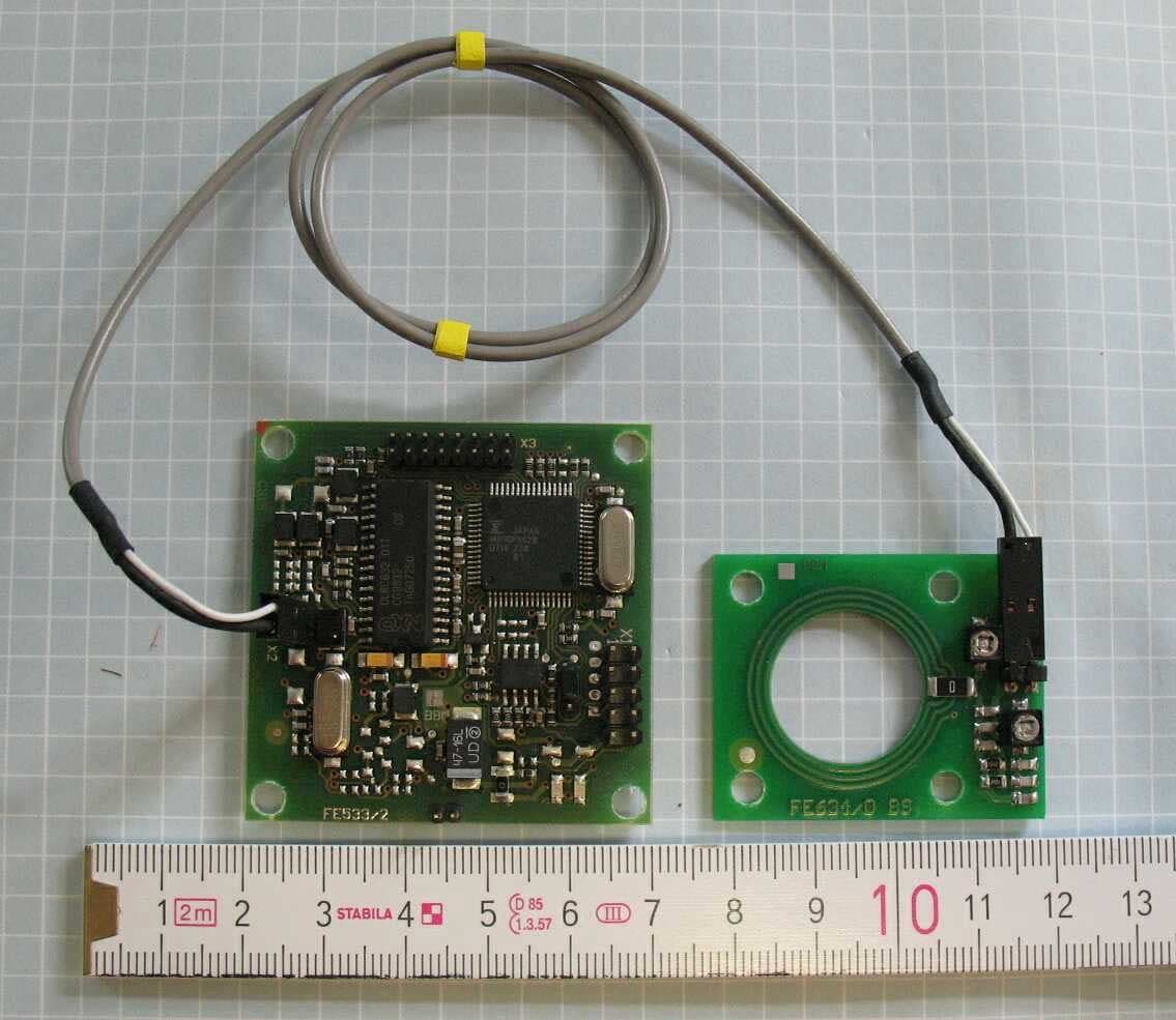
Click to zoom
Application Details
- Equipment Class
- DXX - Part 15 Low Power Communication Device Transmitter
- Date of Grant
- Dec 13, 2007
- Application Purpose
- Original Equipment
- Date of Application
- Dec 13, 2007
- Equipment Note
- Inductive Tag Reader Module
- Frequency Range
- 13.56000000 - 13.56000000
- Company
- Feig Electronic GmbH
- Country
- Germany
Documents & Files
Document Text
Text extracted from the exhibit documents filed with the FCC. Open a document above to read the original.
Users Manual
OBID ® classic-proInstallationID CPR.M02/ANT19 FEIG ELECTRONIC GmbHPage 2 of 20Manual-M21001-3de-ID-B.doc ID CPR.M02/ANT19 ID CPR.M02.VP/AB-CA with ID ICS.ANT19 (english) OBID ® classic-proInstallationID CPR.M02/ANT19 FEIG ELECTRONIC GmbHPage 3 of 20Manual-M21001-3de-ID-B.doc Note © Copyright 2002 - 2006 by FEIG ELECTRONIC GmbH Lange Strasse 4 D-35781 Weilburg-Waldhausen Tel.: +49 6471 3109-0 http://www.feig.de Edition: bs/07/10/30 - manual-m21001-3de-id-b.doc With the edition of this manual, all previous editions become void. Indications made in this manual may be changed without previous notice. Copying of this document, and giving it to others and the use or communication of the contents thereof are forbidden without express authority. Offenders are liable to the payment of damages. All rights are reserved in the event of the grant of a patent or the registration of a utility model or design. Composition of the information in this manual has been done to the best of our knowledge. FEIG ELECTRONIC GmbH does not guarantee the correctness and completeness of the details given in this manual and may not be held liable for damages ensuing from incorrect or incomplete information. Since, despite all our efforts, errors may not be completely avoided, we are always grateful for your useful tips. The installation instructions given in this manual are based on advantageous boundary conditions. FEIG ELECTRONIC GmbH does not give any guarantee promise for perfect function in cross environments. FEIG ELECTRONIC GmbH assumes no responsibility for the use of any information contained in this manual and makes no representation that they free of patent infringement. FEIG ELECTRONIC GmbH does not convey any license under its patent rights nor the rights of others. OBID ® and OBID i-scan ® is a registered trademark of FEIG ELECTRONIC GmbH. I-CODE ® and mifare ® is a registered trademark of Philips Electronics N.V. my-d ® is a registered trademark of Infineon Technologies AG Tag-it TM is a registered trademark of Texas Instruments Incorporated OBID ® classic-proInstallationID CPR.M02/ANT19 FEIG ELECTRONIC GmbHPage 4 of 20Manual-M21001-3de-ID-B.doc Contents 1. Safety Instructions / Warning - Read before start-up !5 2. Performance Characteristics of the ID CPR.M02 Reader6 2.1. Performance Characteristics .............................................................................................6 2.2. Available module and antenna types ................................................................................6 2.3. Scope of delivery.................................................................................................................6 3. Installation and wiring7 3.1. Dimensions ..........................................................................................................................7 3.2. Wiring ...................................................................................................................................8 3.2.1. Supply voltage ...............................................................................................................9 3.2.2. RS232 interface ...........................................................................................................10 3.2.3. Data/Clock interface ....................................................................................................11 3.2.4. Connection of an external Antenna (ID ISC.ANT19) ...................................................12 3.2.5. Optional Module ID SAM.M02 .....................................................................................13 3.3. Display elements ...............................................................................................................14 3.4. Operating elements...........................................................................................................15 3.4.1. Operating/Programming Mode: Jumper J1..................................................................15 3.4.2. Retuning the internal antenna (ID CPR.M02.VP/AB-C)...............................................16 3.5. Installation notes...............................................................................................................18 3.5.1. Metallic surroundings...................................................................................................18 3.5.2. EMC effects on cables.................................................................................................18 3.5.3. EMC effects from magnetic fields ................................................................................19 4. Radio Approvals20 4.1. Europe (CE)........................................................................................................................20 4.2. USA (FCC) ..........................................................................................................................20 5. Technical Data21 OBID ® classic-proInstallationID CPR.M02/ANT19 FEIG ELECTRONIC GmbHPage 5 of 20Manual-M21001-3de-ID-B.doc 1. Safety Instructions / Warning - Read before start-up ! • The device has to be used only for the purpose designed by the manufacturer. • The operation manual has to be stored available at any time and has to be handed over to each user. • Unauthorized changes and the use of spare parts and additional devices which have not been sold or recommended by the manufacturer may cause fire, electric shocks or injuries. Such measures will lead to exclusion of any liability by the manufacturer. • The liability-prescriptions of the manufacturer in the issue valid at the time of purchase are valid for the device. The manufacturer is not legally responsible for incorrect, unsuitable manual or automatical setting of parameters for a device or the incorrect application of a device. • Repairs can only be executed by the manufacturer. • Installation-, operation- and maintenance procedures should only be carried out by qualified personnel. • Be…
Text truncated - open the document above for the full version.
Cover Letter(s)
Ersteller: U. Rodemeier Revision: 03 Erstelldatum: 03.08.01 Datum: 4.10.2006 Seite 1 von 1 Request for Confidentiality PHOENIX TESTLAB GmbH Date: November 29, 2007 Product Certification Königswinkel 10 D 32825 Blomberg RE: Certification Application FCC ID: PJMCPRM02-ANT19 Confidentiality Request Pursuant to Sections 0.457 and 0.459 of the Commission’s Rule, the applicant hereby requests confidential treatment of information accompanying this application as outlined below: • Schematics • Block Diagram • Technical Description • Parts List The above materials contain trade secrets and proprietary information not customarily released to the public. The public disclosure of these matters might be harmful to the applicant and provide unjustified benefits to its competitors. The applicant understands that pursuant to rule 0.457, disclosure od this application and all accompanying documentation will not be made before the date of the GRANT for this application ́. Thank you for your attention in this matter. Applicant’s Company : Senton GmbH address : Auessere Fruehlingstrasse 45, D-94315 Straubing Signature : Johann Roidt Job Title and Dept. : Technical Director
Cover Letter(s)
EMV-Prüfzentrum EMI/EMC-Testcenter Coordinates: Äussere Frühlingstrasse 45 y D-94315 Straubing Telefon (0 94 21) 55 22-0 Telefax (0 94 21) 55 22-99 [email protected] y http://www.senton.de Senton GmbH y Äussere Frühlingstrasse 45 y D-94315 Straubing PHOENIX TEST-LAB GmbH Koenigswinkel 10 D-32825 Blomberg Germany November 29, 2007 In reference to FCC ID PJMCPRM02-ANT19 Justification for Part 15 Unlicensed Modular Transmitter Approval according to DA 00-1407 1. Own RF Shielding Not complied, but subject to limited modular approval. The Grantee can demonstrate that it will retain control over the final installation of the device, such that compliance of the end product is assured. In such a case, an operating condition on the grant of equipment authorization for the module would state that the module is only approved for use when installed in devices produced by a specific manufacturer, typically the Grantee. 2. Buffered Modulation inputs Complied, see schematic diagrams 3. Own power supply regulation Complied, voltage regulated power supply on board, see schematic diagram 4. Antenna requirements Complied, unique antenna coupler employed 5. Test in stand-alone configuration Complied, see test report for details. Cable lengths typical to actual use. 6. Own FCC ID Complied, the exterior label will be "Contains FCC ID PJMCPRM02-ANT19" 7. Not applicable, the unit operates under Section 15.225 of the FCC Rules 8. RF Exposure requirements Not applicable since the unit operates under section 15.225 of the FCC Rules. The reference guide contains general installation and operation instructions. Johann Roidt Senton GmbH
External Photos
FCC ID PJMCPRM02-ANT19 FCC ID PJMCPRM02-ANT19
ID Label/Location Info
FCC ID PJMCPRM02-ANT19 FCC ID PJMCPRM02-ANT19
Internal Photos
FCC ID PJMCPRM02-ANT19 FCC ID PJMCPRM02-ANT19
Test Report
Test Equipment List for Test Report No. 50602-071031 / Page 1 of 1 Page(s) EMI/EMC-TestcenterEMV-Prüfzentrum Test Equipment List with Calibration Data / Test date: November 2007 No. Type Inv.-No. Model Serial Number Manufacturer Calibration Organization Date of last calibration Date of next calibration 1 1. Test receiver 1028 ESHS 10 860043/016 Rohde & Schwarz Rohde & Schwarz 01/2006 07/2007 2. Test receiver 1025 ESVP 881120/024 Rohde & Schwarz Rohde & Schwarz 10/2006 10/2007 3. Spectrum analyzer 1078 R 3271 05050023 Advantest Rohde & Schwarz 03/2006 03/2008 4. Spectrum analyzer 1666 FSP 30 100063 Rohde & Schwarz Rohde & Schwarz 02/2006 08/2007 5. EMI test receiver 1569 ESMI 839379/013 839587/006 Rohde & Schwarz Rohde & Schwarz 12/2005 12/2007 Matrix RELAX consist: 1941 6. Preamplifier 1142 R14601 13120026 Advantest Rohde & Schwarz 11/2006 11/2007 7. Preamplifier 1651 CPA9231A1 3393 Schaffner Schaffner 02/2007 02/2008 8. Preamplifier 1684 AFS3-00100800-32-LN 847743 Miteq Senton GmbH 06/2006 06/2007 9. V-network 1060 ESH 3-Z5 862770/021 B1060 Rohde & Schwarz Senton GmbH 01/2007 01/2010 10. V-network 1218 ESH 3-Z5 830952/025 B1218 Rohde & Schwarz Senton GmbH 05/2005 05/2008 11. Trilog wide band antenna Chamber 2 1722 VULB 9163 9163-188 A1722 Schwarzbeck Schwarzbeck 10/2006 10/2007 12. Trilog wide band antenna Chamber 3 1802 VULB 9163 9163-214 A1802 Schwarzbeck Schwarzbeck 01/2006 07/2007 13. Biconical antenna EG 1 1518 HK 116 842204/001 Rohde & Schwarz Rohde & Schwarz 02/2007 02/2008 14. Log. per. antenna EG 1 1519 HL 223 841516/023 Rohde & Schwarz Rohde & Schwarz 01/2007 01/2008 15. Horn Antenna 1516 3115 9508-4553 Emco ARC-Seibersdorf 05/2005 05/2008 1 Accepted tolerance is ±6 months.
Test Report
FCC-ID: PJMCPRM02 Test Report No. 50602-20601-2 Page 1 of 29 Pages Straubing, 26 November 2002 T E S T - R E P O R T No. 50602-20601-2 for ID CPR.M02 Inductive Tag Reader Applicant: FEIG ELECTRONIC GmbH Purpose of testing: To show compliance with FCC Code of Federal Regulations, CFR 47, Part 15, Subpart C, Section 15.225 Note: The test data of this report relate only to the individual item which has been tested. This report shall not be reproduced except in full extent without the written approval of the testing laboratory. FCC-ID: PJMCPRM02 Test Report No. 50602-20601-2 Page 2 of 29 Pages Table of Contents 1. Identification of the Test Laboratory .................................................................... 3 2. Administrative Data ............................................................................................. 4 3. Summary of Test Results .................................................................................... 6 4. Deviations from the Test Specifications............................................................... 7 5. Additional Information to EUT and Testing .......................................................... 8 6. Measuring Methods ............................................................................................. 9 7. Photographs of Test Setups .............................................................................. 14 8. Equipment List................................................................................................... 16 9. Referenced Regulations .................................................................................... 18 10. List of Measurements ........................................................................................ 19 11. Test Results ...................................................................................................... 20 12. Charts taken during testing................................................................................ 29 FCC-ID: PJMCPRM02 Test Report No. 50602-20601-2 Page 3 of 29 Pages 1. Identification of the Test Laboratory DETAILS OF THE TEST LABORATORY COMPANY NAME: Senton GmbH EMI/EMC Test Center ADDRESS: Aeussere Fruehlingstrasse 45 D-94315 Straubing Germany LABORATORY ACCREDITATION: DAR-Registration No. TTI-P-G 062/94-40 FCC TEST SITE REGISTRATION NUMBER: 90926 INDUSTRY CANADA FILE NUMBER: IC 3050 NAME FOR CONTACT PURPOSES: Mr. Johann Roidt TELEPHONE: (+49) 09421 5522-0 FAX: (+49) 09421 5522-99 EMAIL: [email protected] PERSONNEL INVOLVED IN THIS TEST REPORT TECHNICAL DIRECTOR: Mr. Johann Roidt RESPONSIBLE FOR TESTING: Mr. Johann Roidt RESPONSIBLE FOR TEST REPORT: Mr. Johann Roidt FCC-ID: PJMCPRM02 Test Report No. 50602-20601-2 Page 4 of 29 Pages 2. Administrative Data IDENTIFICATION OF EUT TYPE DESIGNATION OF EUT (i.e. system if EUT consists of more than one part): ID CPR.M02 PARTS OF THE SYSTEM (including appropriate type designations) Reader module ID CPR.M02 Plug-in module ID SAM.M02 Antenna ID ISC.ANT100100 Antenna ID ISC.ANT4030 SERIAL NUMBER(S): Sample no. 1 APPLICATION (see note): Inductive Applications SECTION OF FCC RULES 15.225 FREQUENCY RANGE: 13.553-13.567 MHz OPERATING FREQUENCY: 13.560 MHz CARRIER POWER 10.000 μV/m at 30 meters CHANNEL SPACING: Wideband ITU DESIGNATION: 10K0A1D NUMBER OF RF-CHANNELS: 1 NUMBER OF CONTROL FUNCTIONS: N/A POWER SUPPLY: 9 V DC or 5V DC TYPE OF ANTENNA: Integrated / External SIZE / LENGTH OF ANTENNA: 40x30 mm, 100x100 mm INTERFACE(S): RS 232 FCC-ID: PJMCPRM02 Test Report No. 50602-20601-2 Page 5 of 29 Pages ADMINISTRATIVE DATA APPLICANT (full address): FEIG ELECTRONIC GmbH Lange Strasse 4 D-35781 Weilburg-Waldhausen CONTACT PERSON: Mr. Elmar Reichwein TELEPHONE NO.: 06471 3109 438 FAX NO.: 06471 3109 99 EMAIL-ADDRESS: [email protected] RECEIPT OF EUT: 14 October 2002 VERSION OF EUT: As delivered DATE(S) OF TEST: October 2002 NOTE(S): --- FCC-ID: PJMCPRM02 Test Report No. 50602-20601-2 Page 6 of 29 Pages 3. Summary of Test Results The tested sample complies with the requirements for set forth in the The Code of Federal Regulations 47, Part 15, Subpart C, Section 15.225 of the Federal Communication Commission (FCC). FCC-ID: PJMCPRM02 Test Report No. 50602-20601-2 Page 7 of 29 Pages 4. Deviations from the Test Specifications All tests were performed without deviations from the test specifications. Note: Full tests were performed with the ID ISC.ANT100100 antenna. Transmitter fundamental power was measured with all antennas. Additional spurious emission measurements were performed with the internal antenna. Only maximum values have been recorded. FCC-ID: PJMCPRM02 Test Report No. 50602-20601-2 Page 8 of 29 Pages 5. Additional Information to EUT and Testing EUT MODE OF OPERATION Continously reading a TAG LIST OF ANCILLARY DEVICES USED FOR TESTING (SEE NOTE) Description Designation Serial no. Manufacturer None LIST OF PERIPHERAL DEVICES USED FOR TESTING Description Designation Serial no. Manufacturer None FCC-ID: PJMCPRM02 Test Report No. 50602-20601-2 Page 9 of 29 Pages 6. Measuring Methods 6.1. Field strength of in-band emissions (§15.225 (a)) and unwanted emissions < 30 MHz (§15.225 (b)) Radiated emissions in the frequency range 9 kHz – 30 MHz will be measured initially at a distance of 3 meters. A prescan at 3 meter distance will be performed in a shielded room with the detector of the spectrum analyzer or EMI Receiver set to peak. Final measurement is then performed at 30 meter distance. In case the regulation requires testing at other distances, the result will be extrapolated. The extrapolation factor will be determined by making a second measurement at 10 meter distance. The provisions of 15.31 (d) apply. According to section 15.209 (d) final measurementis performed with the detector set to Quasi Peak except for the frequency bands 9 – 90 kHz and 110 – 490 kHz where average detector is employed. FCC-ID: PJMCPRM02 Test Report No. 50602-20601-2 Page 10 of 29 Pages 6.2. Frequency tolerance (§15.22…
Text truncated - open the document above for the full version.
Test Report
Senton GmbH Aeussere Fruehlingstrasse 45 D-94315 Straubing Note: The test data of this report is related only to the individual item which has been tested. This report shall not be reproduced except in full extent without the written approval of the testing laboratory. Test Report No. 50602-071031 (Edition 2) Page 1 of 30 Pages Straubing, December 14, 2007 T E S T - R E P O R T No. 50602-071031 (Edition 2) for ID CPR.M02/ANT19 Inductive Tag Reader Applicant: FEIG ELECTRONIC GmbH Test Specifications: FCC Code of Federal Regulations, CFR 47, Part 15, Sections 15.205, 15.207, 15.215 and 15.225 Industry Canada Radio Standards Specifications RSS-Gen Issue 2, Section 7.2.2 and RSS-210 Issue 7, Sections 2.2, 2.6, A2.6 (Category I Equipment) Senton GmbH Aeussere Fruehlingstrasse 45 D-94315 Straubing Test Report No. 50602-071031 (Edition 2) Page 2 of 30 Pages Table of Contents 1 Description of the Equipment Under Test (EUT) ........................................................ 3 2 Administrative Data..................................................................................................... 4 3 Identification of the Test Laboratory ........................................................................... 5 4 Summary .................................................................................................................... 6 5 Operation Mode and Configuration of EUT................................................................. 7 6 Measurement Procedures........................................................................................... 8 6.1 Radiated Emission Measurement 9 kHz to 30 MHz ............................................. 9 6.2 Radiated Emission in Fully or Semi Anechoic Room.......................................... 11 6.3 Radiated Emission at Open Field Test Site........................................................ 13 7 Photographs Taken During Testing .......................................................................... 14 8 Test Results .............................................................................................................. 19 8.1 Radiated Emission Measurement 9 kHz to 30 MHz .......................................... 21 8.2 Radiated Emission Measurement 30 MHz to 1 GHz ......................................... 24 8.3 Exposure of Humans to RF Fields...................................................................... 26 9 Referenced Regulations ........................................................................................... 28 10 Revision History ........................................................................................................ 29 11 Charts taken during testing ....................................................................................... 30 Senton GmbH Aeussere Fruehlingstrasse 45 D-94315 Straubing Test Report No. 50602-071031 (Edition 2) Page 3 of 30 Pages 1 Description of the Equipment Under Test (EUT) General data of EUT Type designation 1 : ID CPR.M02/ANT19 Parts 2 : Serial number(s): Test Sample 01 Manufacturer: FEIG ELECTRONIC GmbH Type of equipment: Inductive Tag Reader Version: As delivered FCC ID: PJMCPRM02-ANT19 Additional parts/accessories: Technical data of EUT Application frequency range: 13.110 - 14.010 MHz Frequency range: 13.56 MHz Operating frequency: 13.56 MHz Type of modulation: ASK Pulse train: --- Pulse width: --- Number of RF-channels: 1 Channel spacing: Not Applicable Designation of emissions 3 : 10K0A1D Type of antenna: Integrated loop on extra printed board Size/length of antenna: Ø 25 mm Connection of antenna: detachable not detachable Type of power supply: DC supply Specifications for power supply: nominal voltage: 5.00 V minimum voltage: 4.75 V maximum voltage: 5.25 V 1 Type designation of the system if EUT consists of more than one part. 2 Type designations of the parts of the system, if applicable. 3 Also known as "Class of Emission". Senton GmbH Aeussere Fruehlingstrasse 45 D-94315 Straubing Test Report No. 50602-071031 (Edition 2) Page 4 of 30 Pages 2 Administrative Data Application details Applicant (full address): FEIG ELECTRONIC GmbH Lange Straße 4 D-35781 Weilburg-Waldhausen Contact person: Mr. Bernhard Schüßler Contract identification: EB205126 / 16483 Receipt of EUT: November 2, 2007 Dates of test: November 2007 Note: This test report intended to show compliance of the module ID CPR.M02 with antenna ANT19. For further details please refer to Senton Test Report No. 50602-20601-2 Report details Report number: 50602-071031 Edition: 2 Issue date: December 14, 2007 Senton GmbH Aeussere Fruehlingstrasse 45 D-94315 Straubing Test Report No. 50602-071031 (Edition 2) Page 5 of 30 Pages 3 Identification of the Test Laboratory Details of the Test Laboratory Company name: Senton GmbH EMI/EMC Test Center Address: Aeussere Fruehlingstrasse 45 D-94315 Straubing Germany Laboratory accreditation: DAR-Registration No. DAT-P-171/94-02 FCC test site registration number 90926 Industry Canada test site registration: IC 3050 Contact person: Mr. Johann Roidt Phone: (+49) (0)9421 5522-0 Fax: (+49) (0)9421 5522-99 Senton GmbH Aeussere Fruehlingstrasse 45 D-94315 Straubing Test Report No. 50602-071031 (Edition 2) Page 6 of 30 Pages 4 Summary Summary of test results The tested sample complies with the requirements set forth in the Code of Federal Regulations CFR 47, Part 15, Sections 15.205, 15.215 and 15.225 of the Federal Communication Commission (FCC) and the Radio Standards Specifications RSS-210 Issue 7, Sections 2.2, 2.6, A2.6 (Category I Equipment) of Industry Canada (IC). Personnel involved in this report Laboratory Manager: Mr. Johann Roidt Responsible for testing: Mr. Martin Steindl Responsible for test report: Mr. Martin Steindl Senton GmbH Aeussere Fruehlingstrasse 45 D-94315 Straubing Test Report No. 50602-071031 (Edition 2) Page 7 of 30 Pages 5 Operation Mode and Configuration of EUT Operation Mode Transmitting continuously Configuration of EUT The EUT wa…
Text truncated - open the document above for the full version.
Test Setup Photos
Senton GmbH Aeussere Fruehlingstrasse 45 D-94315 Straubing Test Report No. 50602-071031 (Edition 1) Page 15 of 30 Pages Test setup for radiated emission measurement 9 kHz – 30 MHz Senton GmbH Aeussere Fruehlingstrasse 45 D-94315 Straubing Test Report No. 50602-071031 (Edition 1) Page 16 of 30 Pages Test setup for radiated emission measurement (fully anechoic room) Senton GmbH Aeussere Fruehlingstrasse 45 D-94315 Straubing Test Report No. 50602-071031 (Edition 1) Page 17 of 30 Pages Test setup for radiated emission measurement (open field test site) Senton GmbH Aeussere Fruehlingstrasse 45 D-94315 Straubing Test Report No. 50602-071031 (Edition 1) Page 18 of 30 Pages Test setup for radiated emission measurement (open field test site) - continued -
Contact Information
Applicant
Elmar Reichwein(Manager)
Test Firm
TUV SUD Product Service GmbH PS-EMC-STRRainer Heller
Technical Specifications
| # | Rule Parts | Frequency Range | Power Output | Tolerance |
|---|---|---|---|---|
| 1 | 15C | 13.56 MHz - 13.56 MHz | - | 0.0100000000 % |
Other Applications from Feig Electronic GmbH

PJMPRM103
Feb 25, 2026RFID Reader
Equipment Class
DXX - Part 15 Low Power Communication Device Transmitter
PJMMRM103
Jan 19, 2026RFID Reader
Equipment Class
DXX - Part 15 Low Power Communication Device TransmitterPJMTSTFSAMC
Dec 01, 2024Wireless Safety System for industrial doors - Mobile Unit
Equipment Class
DXX - Part 15 Low Power Communication Device Transmitter
PJMLRM5400
Jun 27, 2023RFID Reader
Equipment Class
DXX - Part 15 Low Power Communication Device Transmitter
PJMMRU102A
Jul 07, 2021RFID Reader
Equipment Class
DSS - Part 15 Spread Spectrum Transmitter