PJMLRM1002RFID Reader
Feig Electronic GmbH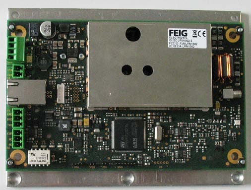
Click to zoom
Application Details
- Equipment Class
- DXX - Part 15 Low Power Communication Device Transmitter
- Date of Grant
- Dec 03, 2012
- Application Purpose
- Original Equipment
- Date of Application
- Dec 03, 2012
- Equipment Note
- RFID Reader
- Frequency Range
- 13.56000000 - 13.56000000
- Company
- Feig Electronic GmbH
- Country
- Germany
Documents & Files
Document Text
Text extracted from the exhibit documents filed with the FCC. Open a document above to read the original.
Users Manual
Date: 2012-06-11 Vers. no. 1.12 m. dudde hochfrequenz-technik Rottland 5a D-51429 Bergisch Gladbach/ Germany Tel: +49 2207-96890 Fax +49 2207-968920 Annex no. 5 User Manual INTEGRATION final – public (B) 2012-11-23 – M21110-0e-ID-B-P.docx ID ISC.LRM1002-E Long Range Reader Modul (English) OBID i-scan ® HF Integration Manual ID ISC.LRM1002-E FEIG ELECTRONIC GmbH Page 2 from 24 M21110-0e-ID-B -P.docx Note Copyright 2012 by FEIG ELECTRONIC GmbH Lange Strasse 4 D-35781 Weilburg-Waldhausen Tel.: +49 6471 3109-0 http://www.feig.de With the edition of this document, all previous editions become void. Indications made in this manual may be changed without previous notice. Copying of this document, and giving it to others and the use or communication of the contents thereof are forbidden without express authority. Offenders are liable to the payment of damages. All rights are reserved in the event of the grant of a patent or the registration of a utility model or design. Composition of the information in this document has been done to the best of our knowledge. FEIG ELECTRONIC GmbH does not guarantee the correctness and completeness of the details given in this manual and may not be held liable for damages ensuing from incorrect or incomplete information. Since, despite all our efforts, errors may not be completely avoided, we are always grateful for your useful tips. The instructions given in this manual are based on advantageous boundary conditions. FEIG ELECTRONIC GmbH does not give any guarantee promise for perfect function in cross environments. FEIG call explicit attention that devices which are subject of this document are not designed with compo- nents and testing methods for a level of reliability suitable for use in or in connection with surgical implants or as critical components in any life support systems whose failure to perform can reasonably be expected to cause significant injury to a human. To avoid damage, injury, or death, the user or application designer must take reasonably prudent steps to protect against system failures. FEIG ELECTRONIC GmbH assumes no responsibility for the use of any information contained in this docu- ment and makes no representation that they free of patent infringement. FEIG ELECTRONIC GmbH does not convey any license under its patent rights nor the rights of others. OBID ® and OBID i-scan ® are registered trademarks of FEIG ELECTRONIC GmbH. OBID i-scan ® HF Integration Manual ID ISC.LRM1002-E FEIG ELECTRONIC GmbH Page 3 from 24 M21110-0e-ID-B -P.docx Content 1 Safety Instructions / Warning - Read before start-up ! 4 2 Performance Features of Reader Family ID ISC.LRM1002 5 2.1 Performance Features .................................................................................................. 5 2.2 Available Reader Types ................................................................................................ 5 3 Installation and mounting 6 3.1 Mounting ID ISC.LRM1002-E ........................................................................................ 6 3.2 Terminals ....................................................................................................................... 7 3.2.1 Antenna connection .................................................................................................... 8 3.2.1.1 Connection of a ID ISC.DAT (Dynamic Antenna Tuning Board) ....................... 9 3.2.2 Supply voltage .......................................................................................................... 10 3.2.3 OptocouplerInputs (X5 / IN1) .................................................................................... 11 3.3 Relay (X6 / REL1) ......................................................................................................... 13 3.3.1 Output 24V (X5 / VIN, GND) ............................................................................. 14 3.4 Interfaces ..................................................................................................................... 15 3.4.1 RS232-Interface X4 .................................................................................................. 15 3.4.2 USB – Interface X11 (Host Communication) ............................................................ 16 3.4.3 Ethernet-Interface on X3 (10/100 Base-T) ................................................................ 17 4 Operating and Display Elements 18 4.1 LEDs ............................................................................................................................. 18 5 Radio Approvals 19 5.1 Europe (CE) .................................................................................................................. 19 5.2 USA (FCC) and Canada (IC) ........................................................................................ 20 6 Technical Data 23 OBID i-scan ® HF Integration Manual ID ISC.LRM1002-E FEIG ELECTRONIC GmbH Page 4 from 24 M21110-0e-ID-B -P.docx 1 Safety Instructions / Warning - Read before start-up ! • The device may only be used for the purpose intended by the manufacturer. • The operation manual should be kept readily available at all times for each user. • Unauthorized changes and the use of spare parts and additional devices which have not been sold or recommended by the manufacturer may cause fire, electric shocks or injuries. Such unauthorized measures shall exclude the manufacturer from any liability. • The liability-prescriptions of the manufacturer in the issue valid at the time of purchase are valid for the device. The manufacturer shall not be held legally responsible for inaccuracies, errors, or omissions in the manual or automatically set parameters for a device or for an incorrect application of a device. • Repairs may only be undertaken by the manufacturer. • Installation, operation, and maintenance procedures should only be carried out by qualified personnel. • Use of the device and its installation must be in accordance…
Text truncated - open the document above for the full version.
Cover Letter(s)
m. dudde hochfrequenz-technik Rottland 5a, D-51429 Bergisch-Gladbach DIN EN ISO/IEC 17025 certified DAkkS accreditation number: D-PL-12053-01 Tel. : +49 22 07 - 96 89 - 0 Fax : +49 22 07 - 96 89 - 20 email: [email protected] www.dudde.com Request for Confidentiality Date: 2012-08-10 FCC ID: PJMLRM1002 To whom it may concern, Pursuant to sections 0.457(d) and 0.459 of CFR 47 and to avoid premature release of sensitive information prior to marketing or release of the product to the public, our customer FEIG ELECTRONIC GmbH hereby requests long-term confidential treatment of information accompanying this application as outlined below: Schematics Parts List & layouts Block Diagram Operational Description In addition they hereby request the following exhibits contained in this application to be temporarily (short-term confidentiality) withheld from the public disclosure for an initial period of days until: not applicable External Photos Test Setup Photos Internal Photos Users Manual The above materials contain trade secrets and proprietary information not customarily released to the public. The public disclosure of these matters might be harmful to the applicant and provide unjustified benefits to its competitors. The applicant understands that pursuant to rule 0.457(d), disclosure of this application and all accompanying documentation will not be made before the date of the GRANT for this application. Thank you for your attention in this matter. m. dudde hochfrequenz-technik Andreas Morsbach Management Assistant
Cover Letter(s)
m. dudde hochfrequenz-technik Rottland 5a, D-51429 Bergisch-Gladbach DIN EN ISO/IEC 17025 certified DAkkS accreditation number: D-PL-12053-01 Tel. : +49 22 07 - 96 89 - 0 Fax : +49 22 07 - 96 89 - 20 email: [email protected] www.dudde.com Attn: Reviewing Engineer RE: FCC Part 15C LIMITED MODULAR TRANSMITTER APPROVAL To Whom It May Concern: Our customer, FEIG ELECTRONIC GmbH, hereby requests host specific limited modular approval acc. to FCC Part 15 (Modular Approval) Brand/Trade name: OBID i-scan Model name: ID ISC.LRM1002-E FCC certification number: PJMLRM1002 Transmitters designed as modules for the installation in a host device may obtain equipment certification as a modular device provided that the applicable FCC part is met and the following conditions in this section are met. Items to be covered Answer from applicant 1. The modular transmitter must have its own RF shielding. YES, see internal photographs "Annex No. 2" 2. The modular transmitter must have buffered modulation/data inputs (if such inputs are provided) to ensure that the module will comply with Part 15 requirements under conditions of excessive data rates or over-modulation. YES 3. The modular transmitter must have its own power supply regulation. YES 4. The modular transmitter must comply with the antenna requirements of Section 15.203 and 15.204(c). The antenna must either be permanently attached or employ a “unique” antenna coupler (at all connections between the module and the antenna, including the cable). NO, the RF module has an embedded SMA connector and will be integrated into host devices subject to professional installation 5. The modular transmitter must be tested in a stand-alone configuration, i.e., the module must not be inside another device during testing. This is intended to demonstrate that the module is capable of complying with Part 15 emission limits regardless of the device into which it is eventually installed. NO, the RF module was tested in single aluminum housing and in a plastic housing in combination with ID ISC.ANT1300/680, see test setup photographs "Annex No. 6" m. dudde hochfrequenz-technik Rottland 5a, D-51429 Bergisch-Gladbach DIN EN ISO/IEC 17025 certified DAkkS accreditation number: D-PL-12053-01 Tel. : +49 22 07 - 96 89 - 0 Fax : +49 22 07 - 96 89 - 20 email: [email protected] www.dudde.com 6. The modular transmitter must be labeled with its own FCC ID number, and, if the FCC ID is not visible when the module is installed inside another device, then the outside of the device into which the module is installed must also display a label referring to the enclosed module. This exterior label can use wording such as the following: “Contains Transmitter Module FCC ID: XYZMODEL1” or “Contains FCC ID: XYZMODEL1.” Any similar wording that expresses the same meaning may be used. The Grantee may either provide such a label, an example of which must be included in the application for equipment authorization, or, must provide adequate instructions along with the module which explain this requirement. In the latter case, a copy of these instructions must be included in the application for equipment authorization. YES, see label sample "Annex No. 4" and Integration manual “Annex No. 5” 7. The modular transmitter must comply with any specific rule or operating requirements applicable to the transmitter and the manufacturer must provide adequate instructions along with the module to explain any such requirements. A copy of these instructions must be included in the application for equipment authorization. For example, there are very strict operational and timing requirements that must be met before a transmitter is authorized for operation under Section 15.231. For instance, data transmission is prohibited, except for operation under Section 15.231(e), in which case there are separate field strength level and timing requirements. Compliance with these requirements must be assured. YES 8. The modular transmitter must comply with any applicable RF exposure requirements. For example, FCC Rules in Sections 2.1091, 2.1093 and specific Sections of Part 15, including 15.319(i), 15.407(f), 15.253(f) and 15.255(g), require that Unlicensed PCS, UNII and millimeter wave devices perform routine environmental evaluation for RF Exposure to demonstrate compliance. In addition, spread spectrum transmitters operating under Section 15.247 are required to address RF Exposure compliance in accordance with Section 15.247(b)(4). Modular transmitters approved under other Sections of Part 15, when necessary, may also need to address certain RF Exposure concerns, typically by providing specific installation and operating instructions for users, installers and other interested parties to ensure compliance. YES Note: If compliance with one or more of the numbered requirements, listed above, cannot be demonstrated, it may be possible to obtain a “Limited Modular Approval” (LMA). m. dudde hochfrequenz-technik Andreas Morsbach Management Assistant
Cover Letter(s)
Equality Declaration ID ISC.LR(M)1002 1 / 1 File : ID ISCLRM1002-Equality Decalaration.pdf Date : 17.10.2012 Product Equality Declaration ID ISC.LRM1002-E / ID ISC.LR1002-E The HF Reader device ID ISC.LRM1002-E and the device ID ISC.LR1002-E are identical devices based on the same electronic printed boards with the same parts. Both Readers has the same RF device, one digital input, a relay output, an RS232 interface, a LAN interface and a USB interface. The differences between the devices are the housing, only. The reader ID ISC.LRM1002-E is the module version, mounted on a simple metal plate. The reader ID ISC.LR1002-E is mounted in a closed aluminum housing. At the device ID ISC.ANT1300/680, the reader module ID ISC.LRM1002-E is mounted in the antenna base.
External Photos
Date: 2012-06-11 Vers. no. 1.12 m. dudde hochfrequenz-technik Rottland 5a D-51429 Bergisch Gladbach/ Germany Tel: +49 2207-96890 Fax +49 2207-968920 Annex no. 1 External Photographs 1 ID ISC.LRM1002-E - External Fotos.doc WM14.11.2012 11:10:00 FEIG ELECTRONIC GmbH External Photos: Reader Module ID ISC.LRM1002-E Editor: Wolfgang Meißner Date: 14.11.12 Titel: 1 ID ISC.LR1002-E - External Fotos.doc WM14.11.2012 10:41:00 FEIG ELECTRONIC GmbH External Photos: Reader ID ISC.LR1002-E Editor: Wolfgang Meißner Date: 14.11.12 1 ID ISC.ANT1300680 - External Fotos.doc WM14.11.2012 11:27:00 FEIG ELECTRONIC GmbH External Photos: Antenna ID ISC.ANT1300/680-A with Reader Module ID ISC.LRM1002-E Editor: Wolfgang Meißner Date: 14.11.12 2 ID ISC.ANT1300680 - External Fotos.doc WM14.11.2012 11:27:00 FEIG ELECTRONIC GmbH
ID Label/Location Info
Date: 2012-06-11 Vers. no. 1.12 m. dudde hochfrequenz-technik Rottland 5a D-51429 Bergisch Gladbach/ Germany Tel: +49 2207-96890 Fax +49 2207-968920 Annex no. 4 Label Sample ID ISC.LRM1002-E Label Position.doc WM13.11.2012 16:17:00 FEIG ELECTRONIC GmbH Label information and Label position Reader Module ID ISC.LRM1002-E Editor: Wolfgang Meißner Date: 13.11.12 Titel: 1 ID ISC.LR1002-E Label Position.doc WM13.11.2012 16:13:00 FEIG ELECTRONIC GmbH Label information and Label position Reader ID ISC.LR1002-E Editor: Wolfgang Meißner Date: 13.11.12 Titel: 1 ID ANT1300680-A Label Position.doc WM13.11.2012 16:34:00 FEIG ELECTRONIC GmbH Label information and Label position Antenna ID ISC.ANT1300/680-A with Reader ID ISC.LRM1002-E Editor: Wolfgang Meißner Date: 13.11.12
Internal Photos
Date: 2012-06-11 Vers. no. 1.12 m. dudde hochfrequenz-technik Rottland 5a D-51429 Bergisch Gladbach/ Germany Tel: +49 2207-96890 Fax +49 2207-968920 Annex no. 2 Internal Photographs Date: 2012-06-11 Vers. no. 1.12 m. dudde hochfrequenz-technik Rottland 5a D-51429 Bergisch Gladbach/ Germany Tel: +49 2207-96890 Fax +49 2207-968920 Date: 2012-06-11 Vers. no. 1.12 m. dudde hochfrequenz-technik Rottland 5a D-51429 Bergisch Gladbach/ Germany Tel: +49 2207-96890 Fax +49 2207-968920 Date: 2012-06-11 Vers. no. 1.12 m. dudde hochfrequenz-technik Rottland 5a D-51429 Bergisch Gladbach/ Germany Tel: +49 2207-96890 Fax +49 2207-968920
Test Report
Date: 2012-06-11 Vers. no. 1.12 m. dudde hochfrequenz-technik Rottland 5a D-51429 Bergisch Gladbach/ Germany Tel: +49 2207-96890 Fax +49 2207-968920 Annex no. 12 Antenna Descriptions FEATURES More than 30 cm read range Modern design No tag reading outside of the antenna area Optical feedback via LED No detuning of the antenna when installing on metal or rather conductive material Available as external antenna or with integrated reader Shielded HF Pad Antenna ID ISC.ANTS370/270 ID ISC.SPAD102 TECHNICAL DATA Dimensions (W x H x D) 376 mm x 276 mm x 27 mm (14,8 inch x 10,9 inch x 1,1 inch) Weight approx. 2 kg (4,4 lbs) Housing - Pad Acrylic glass - Upper part Plastic SB - Lower part Zinced steel Colour - Pad transparent; black - Upper part similar RAL 9003 (white) Protection class IP 30 Temperature range - Operation –25 °C up to 55 °C (-13 °F up to 131 °F) - Storage –25 °C up to 70 °C (-13 °F up to 158 °F) Relative air humidity 5...95 % (non-condensing) Operating frequency 13,56 MHz Max. input power 1,5 W Antenna connection RG58 coaxial cable with SMA connector (50 Ω); approx. 2,3m long (90.5 inch) Indicator, optical 1 LED (blue; switchable via DC voltage at the antenna output of the reader) STANDARD CONFORMITY EMC EN 301 489 Safety Electrical safety EN 60950 Human exposure EN 50364 DESCRIPTION The ID ISC.ANTS370/270-A is designed as a very flat and external antenna for contactless data exchange with common HF transponders and is attractive with its outstanding performance and the modern design. With these features the antenna is suitable for desktop applications in offices and libraries to trace files or documents and to detect lendable items at the check out or return point. The read range with single transponders could reach more than 30 cm. Due to its integrated shielding transponders will be detected only inside the antenna area and interferences between several antennas will be minimized. Additionally the installation on metallic or conductive surfaces has no influence on the antenna. Therefor the ID ISC.ANTS370/270-A could be used in normally unsuitable environments. The antenna ID ISC.ANTS370/270-A has an included coaxial cable to connect it directly to a reader. To indicate different conditions the blue LED could be powered with a DC voltage on the antenna output of the reader. FEIG ELECTRONIC reserves the right to change specification without notice at any time. Stand of information: September 2011. ID ISC.ANTS370/270-A ORDER DESCRIPTION ID ISC.ANTS370/270-A Shielded, external antenna with coaxial cable FEATURES Optimal Price-Performance Ratio Easy Installation Neutral Design Multiple Installation Options Optional Functions Flexible IT Integration International Approvals HF Clear Gate ID ISC.ANT1300/680 TECHNICAL DATA Mechanical Data Dimensions (W x H x D) Antenna 720 x 1590 x 80 mm +/- 3 mm Packaging 800 x 1720 x 160 mm +/- 10 mm Housing Plastic ABS UV stabilized Color Antenna frame Light grey RAL 7035 Antenna base Signal black RAL 9004 Weight ID ISC.ANT1300/680-A approx.16 kg /21 kg with packaging ID ISC.ANT1300/680-B approx.15 kg /20 kg with packaging ID ISC.ANT1300/680-BL approx.15 kg /20 kg with packaging Protection class IP 43 Max. horizontal load on the upper edge of the antenna 250 N* Electri cal Data Operating frequency 13.56 MHz Transmitting power Reader 1 W up to 5 W (adjustable) Supply voltage 24 V +/- 15% Noise Ripple: maximum 150 mV Power consumption maximum 16 VA Permissible total transmitting power per Antenna Gate Europe (EN 300 330) 5.0 W USA (FCC Part 15) 5.0 W Canada (RSS210) 5.0 W Outputs 1 Relay (1 x NO) 24 V / 1 A resp. Alarm Kit Inputs 1 Opto coupler 24 V / 6 mA Interfaces RS232, USB, Ethernet (TCP/IP) Antenna connection 1 x SMA plug (50 Ω) Antenna connection cable Types –B and -BL RG58, 50 Ω, approx. 2.0 m long *Permanent deformation after unloading approx. 1 cm FEIG ELECTRONIC reserves the right to change specification without notice at any time. State of information: June 2012. Order descriptions - ID ISC.ANT1300/680-A Clear Gate (Base) Gate Antenna with Reader, Power Splitter, Sounder, Alarm Light and Manual Antenna Tuning Board - ID ISC.ANT1300/680-B Clear Gate Gate Antenna with Manual Antenna Tuning Board - ID ISC.ANT1300/680-BL Clear Gate (Light) Gate Antenna with Alarm Light and Manual Antenna Tuning Board TECHNICAL DATA Functions Operation Modes FEIG ISO HOST Buffered Read Mode (BRM, maximum 100 data records) Notification Mode (TCP/IP) Supported Transponders ISO 15693, ISO 18000-3-A (EM HF ISO Chips, Fujitsu HF ISO Chips, KSW Sensor Chips, Infineon my-d, NXP I- Code, STM ISO Chips, TI Tag-it) Angle width (with Power Splitter) unidimensional up to 120 cm tridimensional up to 90 cm Alarm function Automatically without host connection; EAS, AFI, UID/SNR Alarm (Type –A) Sounder & LED Alarm light (red) Tuning Manual (jumper) Tuned ex factory for angle width of 90 cm Environmental conditions Temperature range Operation -25°C up to +50°C Storage -25°C up to +70°C Standard conformity Radio approval Europe EN 300 330 USA FCC Part 15 Canada RSS 210 EMC EN 301 489 Safety Low voltage UL 60950-1 Human Exposure EN 50364 FEIG ELECTRONIC reserves the right to change specification without notice at any time. State of information: June 2012. Order descriptions - ID ISC.ANT1300/680-A Clear Gate (Base) Gate Antenna with Reader, Power Splitter, Sounder, Alarm Light and Manual Antenna Tuning Board - ID ISC.ANT1300/680-B Clear Gate Gate Antenna with Manual Antenna Tuning Board - ID ISC.ANT1300/680-BL Clear Gate (Light) Gate Antenna with Alarm Light and Manual Antenna Tuning Board FEATURES ¼ Transmission power up to 8 W ¼ Protection class IP65 ¼ Useful in many ways with several readers of the OBID i-scan ® HF family ¼ Manual alignment electronics for optimal adjustment to different surrounding conditions HF Loop Antenna ID ISC.ANT310/310 ¼ TECHNICAL DATA Dimensions (B x H x T) 318 mm x 338 mm x 30 mm Weight approx. 700 g Housing Plastic…
Text truncated - open the document above for the full version.
Test Report
Test report no. 12007794 Page 1 of 35 EUT: ID ISC.LRM1002-E FCC ID: PJMLRM1002 Date of issue: 2012-08-04 Date: 2011-03-14 Vers. no. 1.11 dudde hochfrequenz-technik Rottland 5a D-51429 Bergisch Gladbach/ Germany Tel: +49 2207-96890 Fax +49 2207-968920 Test Report acc. to FCC Title 47 CFR Part 15 relating to FEIG ELECTRONIC GmbH ID ISC.LRM1002-E Title 47 - Telecommunication Part 15 - Radio Frequency Devices Subpart C – Intentional Radiators Measurement Procedure: ANSI C63.4-2009 Test report no. 12007794 Page 2 of 35 EUT: ID ISC.LRM1002-E FCC ID: PJMLRM1002 Date of issue: 2012-08-04 Date: 2011-03-14 Vers. no. 1.11 dudde hochfrequenz-technik Rottland 5a D-51429 Bergisch Gladbach/ Germany Tel: +49 2207-96890 Fax +49 2207-968920 Manufacturer’s details Manufacturer FEIG ELECTRONIC GmbH Manufacturer’s grantee code PJM Manufacturer’s address FEIG ELECTRONIC GmbH Lange. Str. 4 35781 Weilburg Germany Phone: +49 (0) 6471 31 09 0 Fax: +49 (0) 6471 31 09 99 Email: [email protected] Relevant standard used 47 CFR Part 15C - Intentional Radiators ANSI C63.4-2009 Test Report prepared by Technical engineer Ralf Trepper m. dudde hochfrequenz-technik (laboratory) Rottland 5a 51429 Bergisch Gladbach Germany Phone: +49 2207 96890 Fax: +49 2207 968920 Email: [email protected] Equipment Under Test (EUT) Equipment category Inductive application / RFID Trade name Type designation ID ISC.LRM1002-E Serial no. --- Variants with antenna variants ID ISC.ANT310/310 ID ISC.ANTS370/270 ID ISC.ANT1300/680* * Antenna Type A alternative with power splitter or multiplexer Test report no. 12007794 Page 3 of 35 EUT: ID ISC.LRM1002-E FCC ID: PJMLRM1002 Date of issue: 2012-08-04 Date: 2011-03-14 Vers. no. 1.11 dudde hochfrequenz-technik Rottland 5a D-51429 Bergisch Gladbach/ Germany Tel: +49 2207-96890 Fax +49 2207-968920 1. Test results Clause Requirements headline Test result Report page number 8.1 Antenna Requirement Pass Fail N.t.* 10 8.2 Restricted bands of operation Pass Fail N.t.* 11 to 12 8.3 Conducted limits Pass Fail N.t.* 13 to 16 8.4 Radiated emission limits Pass Fail N.t.* 17 to 28 8.5 Frequency tolerance Pass Fail N.t.* 29 to 32 * Not tested The equipment meets the requirements Yes No Signature: ............................. Signature: ............................. (Technician) (Manager) Test report no. 12007794 Page 4 of 35 EUT: ID ISC.LRM1002-E FCC ID: PJMLRM1002 Date of issue: 2012-08-04 Date: 2011-03-14 Vers. no. 1.11 dudde hochfrequenz-technik Rottland 5a D-51429 Bergisch Gladbach/ Germany Tel: +49 2207-96890 Fax +49 2207-968920 Table of contents 1. Test results ........................................................................................................................................................ 3 2. Introduction ...................................................................................................................................................... 5 3. Testing laboratory ............................................................................................................................................ 5 4. Applicant .......................................................................................................................................................... 6 5. Product and product documentation ................................................................................................................ 6 6. Conclusions, observations and comments ....................................................................................................... 7 7. Operational description ..................................................................................................................................... 8 8. Compliance assessment .................................................................................................................................... 10 8.1 Antenna requirement ...................................................................................................................................... 10 8.1.1 Regulation ............................................................................................................................................. 10 8.1.2 Result .................................................................................................................................................... 10 8.2 Restricted bands of operation ........................................................................................................................ 11 8.2.1 Regulation ............................................................................................................................................. 11 8.2.2 Result .................................................................................................................................................... 12 8.3 Conducted limits ............................................................................................................................................ 13 8.3.1 Regulation ............................................................................................................................................. 13 8.3.2 Test equipment ..................................................................................................................................... 14 8.3.3 Test procedures ..................................................................................................................................... 14 8.3.4 Result .................................................................................................................................................... 15 8.4 Radiated emission limits ................................................................................................................................ 17 8.4.1 Regulation ............................................................................................................................................. 17 8.4.2 Test equi…
Text truncated - open the document above for the full version.
Test Setup Photos
State: 2010-03-01 Vers. no.: 1.10 m. dudde hochfrequenz-technik Rottland 5a D-51429 Bergisch Gladbach/ Germany Tel. +49 2207-96890 Fax +49 2207 968920 Annex no. 6 Test Setup Photographs State: 2010-03-01 Vers. no.: 1.10 m. dudde hochfrequenz-technik Rottland 5a D-51429 Bergisch Gladbach/ Germany Tel. +49 2207-96890 Fax +49 2207 968920 ID ISC.LR1002-E with antenna ID ISC.ANT310/310 State: 2010-03-01 Vers. no.: 1.10 m. dudde hochfrequenz-technik Rottland 5a D-51429 Bergisch Gladbach/ Germany Tel. +49 2207-96890 Fax +49 2207 968920 ID ISC.LR1002-E with antenna ID ISC.ANTS370/270 State: 2010-03-01 Vers. no.: 1.10 m. dudde hochfrequenz-technik Rottland 5a D-51429 Bergisch Gladbach/ Germany Tel. +49 2207-96890 Fax +49 2207 968920 ID ISC.LRM1002-E with antenna ID ISC.ANT1300/680 State: 2010-03-01 Vers. no.: 1.10 m. dudde hochfrequenz-technik Rottland 5a D-51429 Bergisch Gladbach/ Germany Tel. +49 2207-96890 Fax +49 2207 968920 Conducted emissions 1.) Tested with external DC power supply 2.) Tested with USB connection to an HP Laptop (Type: compaq nx6325 / SN CNU64907YN)
Contact Information
Applicant
Elmar Reichwein(Manager)
Test Firm
m. dudde hochfrequenz-technikManfred Dudde
Technical Specifications
| # | Rule Parts | Frequency Range | Power Output | Tolerance |
|---|---|---|---|---|
| 1 | 15C | 13.56 MHz - 13.56 MHz | - | 0.0100000000 % |
Other Applications from Feig Electronic GmbH

PJMPRM103
Feb 25, 2026RFID Reader
Equipment Class
DXX - Part 15 Low Power Communication Device Transmitter
PJMMRM103
Jan 19, 2026RFID Reader
Equipment Class
DXX - Part 15 Low Power Communication Device TransmitterPJMTSTFSAMC
Dec 01, 2024Wireless Safety System for industrial doors - Mobile Unit
Equipment Class
DXX - Part 15 Low Power Communication Device Transmitter
PJMLRM5400
Jun 27, 2023RFID Reader
Equipment Class
DXX - Part 15 Low Power Communication Device Transmitter
PJMMRU102A
Jul 07, 2021RFID Reader
Equipment Class
DSS - Part 15 Spread Spectrum Transmitter