PJMLRM200ATag Reader System for industrial applications
Feig Electronic GmbH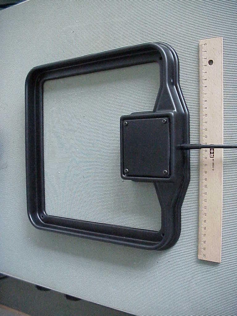
Click to zoom
Application Details
- Equipment Class
- DXX - Part 15 Low Power Communication Device Transmitter
- Date of Grant
- May 09, 2001
- Application Purpose
- Original Equipment
- Date of Application
- Apr 10, 2001
- Equipment Note
- Tag Reader System for industrial applications
- Frequency Range
- 13.56000000 - 13.56000000
- Company
- Feig Electronic GmbH
- Country
- Germany
Documents & Files
Document Text
Text extracted from the exhibit documents filed with the FCC. Open a document above to read the original.
Users Manual
M00602-1e-ID-B.DOC OBID i-scan Installation Instructions ID ISC.LRM200-A/B Identification System OBID i-scan Page 2 of 20FEIG ELECTRONIC GmbH Copyright 2000 byFEIG ELECTRONIC GmbH Lange Straße 4 D-35781 Weilburg-Waldhausen Germany http://www.feig.de Edition: er/01/01/04 - m00602-1e-id-b.doc With the edition of this manual, all previous editions become void. Indications made in this manual may be changed without previous notice. The reproduction of this document as well as the utilization and communication of its contents are strictly forbidden, as far as not expressly conceded. Any contravention will lead to a liability for damages. All rights reserved for the case of patent grant respectively the registration of a utility or design. Composition of the information in this manual has been done to the best of our knowledge. FEIG ELECTRONIC GmbH does not guarantee the correctness and completeness of the details given in this manual and may not be held liable for damages ensuing from incorrect or incomplete information. Since, despite all our efforts, errors may not be completely avoided, we are always grateful for your useful tips. The installation instructions given in this manual are based on advantageous boundary conditions. FEIG ELECTRONIC GmbH does not give any guarantee promise for perfect function of an OBID ® -system in cross surroundings. FEIG ELECTRONIC GmbH assumes no responsibility for the use of any information contained in this manual and makes no representation that they free of patent infringement. FEIG ELECTRONIC GmbH does not convey any license under its patent rights nor the rights of others. OBID ® and i- scan ® are registered trademarks of FEIG ELECTRONIC GmbH. Installation Instructions ID ISC.LRM200-A/B FEIG ELECTRONIC GmbHPage 3 of 20 Contents: 1. Safety Instructions / Warning ......................................................................................4 2. Features of the ID ISC.LRM200-A/B Reader Module ..................................................5 2.1. Features ............................................................................................................................. 5 2.2. Available modules ............................................................................................................. 5 3. Installation and wiring ..................................................................................................6 3.1. Terminals, sockets and switches ..................................................................................... 7 3.2. Antenna connection .......................................................................................................... 8 3.3. Supply voltage ................................................................................................................... 9 3.4. X7: Inputs (optocoupler isolated) ................................................................................... 10 3.5. X6: Output (optocoupler isolated) .................................................................................. 11 3.6. X11: Relay ........................................................................................................................ 12 3.7. X9: RS485 interface ......................................................................................................... 13 3.8. X10: RS232 interface ....................................................................................................... 14 4. Control and display elements ....................................................................................15 4.1. LED ́s ................................................................................................................................ 15 4.2. Buttons / switches........................................................................................................... 16 5. Startup .........................................................................................................................17 5.1. Interface configuration using jumpers........................................................................... 17 5.2. Setting addresses for bus operation.............................................................................. 18 6. Technical Data for ID ISC.LRM200-A/B .....................................................................19 Identification System OBID i-scan Page 4 of 20FEIG ELECTRONIC GmbH 1. Safety Instructions / Warning Read before startup ! • The device may be used only for the purpose intended by the manufacturer. • The Installation Instruction should be kept in an accessible location and handed out to every user and maintenance person. • Non-approved modifications and the use of replacement parts and accessories which have not been purchased or recommended by the manufacturer of the device may cause fires, electrical shocks and injury. This will furthermore result in exclusion of liability and loss of warranty on the part of the manufacturer. • The warranty conditions in effect at the time of purchase shall be considered valid. No liability is assumed for inappropriate, improper manual or automatic setting of parameters for a device or for improper use of a device. • Repairs are to be performed only by the manufacturer. • Hookup, startup, maintenance, measuring and calibration work on the device must be per- formed only by electrical specialists who have received the relevant accident prevention train- ing. • When operating devices with probably live wires, respect the valid security regulations. • Before opening the device always turn off the supply voltage and use a test instrument to verify that the device is unpowered. • The fact that the indicator lamp is off does not necessarily mean that the device has been dis- connected from the power supply or that it is without power. • All work on the device including installation must be in conformance with national electrical regulations as well as with local cod…
Text truncated - open the document above for the full version.
Cover Letter(s)
April 11, 2001 CONFIDENTIALITY REQUEST Federal Communications Commission Authorization and Evaluation Division 7435 Oakland Mills Road Columbia, MD 21046 Re:Feig Electronic application for certification of a Low Power Communications Device; FCC ID: PJMLRM200A Gentlemen: Feig Electronic herein submits an Application for Equipment Authorization to be followed by submission of a fee for $1130.00 along with Form 159 for certification of a low power communications transmitter under FCC Rules Part 15 as required by the FCC Rules. Feig Electronic requests, pursuant to 47CFR 0.459, post grant confidentiality for portions of the material contained in this application such that the identified material will be withheld from public inspection following the grant of this authorization. This material, as indicated by request for confidentiality of the item during the electronic submission process and further identified below, includes: 1. Circuit diagrams submitted as Equipment Authorization Electronic Filing attachment: "schematics" numbering four separate attachments to the application file. 2. Block Diagram 3. Parts List 4. Operational Description Specifically, these exhibits contain information relating to circuit function and complexity that could be of benefit to competitors. The material contains trade secrets and confidential information that Feig Electronic does not customarily release to the public and which is otherwise not generally available to the public. Please contact the undersigned by phone at 410-531-3439, by fax at 410-531-0807, by email at [email protected], or by correspondence at the address below if there are any further questions or additional information needed concerning this filing. Regards, (signed) Phillip Inglis, TRP/Cetecom b.v.b.a. 14085 Howard Rd. Dayton, MD. 21036
External Photos
CETECOM ICT Services GmbH Test report no.: 2_2468-A/01Issue Date: 21.03.2001Page 14 (27) PHOTOGRAPHS OF THE EQUIPMENT ID ISC.ANT300/300A Photograph no.: 1 CETECOM ICT Services GmbH Test report no.: 2_2468-A/01Issue Date: 21.03.2001Page 16 (27) PHOTOGRAPHS OF THE EQUIPMENT ID ISC.ANT300/300A Photograph no.: 3 CETECOM ICT Services GmbH Test report no.: 2_2468-A/01Issue Date: 21.03.2001Page 17 (27) PHOTOGRAPHS OF THE EQUIPMENT ID ISC.ANT1400/700A Photograph no.: 4
ID Label/Location Info
The following label will be affixed to the bottom of the reader module. In addition a separate label will be provided to attach to the enclosure that the reader module is installed in. Equipment Identification Label location on bottom of module: FCC ID: PJMLRM200A
Test Report
CETECOM ICT Services GmbH Radio Satellite Communication Untertürkheimer Straße 6-10 . D-66117 SaarbrückenTelefon: +49 (0)681 598-9100Telefax: -9075 RSC11issue test report consist of27 PagesPage 1 (27) Test report no.: 2_2468-A/01 Additional test report to: 2_2356-B/00 FCC Rule 15.225 ID ISC.ANT300/300A,ID ISC.ANT1400/700A ID ISC.ANT800/600A Akkreditiertes Prüflaboratorium DAR-Registriernummer: TTI-P-G 166/98 CETECOM ICT Services GmbH Test report no.: 2_2468-A/01Issue Date: 21.03.2001Page 2 (27) Table of Contents 1 General information 1.1 Notes 1.2 Testing laboratory 1.3 Details of applicant 1.4 Application details 1.5 Test item 1.6 Test standards 2 Technical test 2.1 Summary of test results 2.2 Test report 1 General information 1.1 Notes The test results of this test report relate exclusively to the test item specified in 1.5. The CETECOM ICT Services GmbH does not assume responsibility for any conclusions and generalisations drawn from the test results with regard to other specimens or samples of the type of the equipment represented by the test item. The test report may only be reproduced or published in full. Reproduction or publication of extracts from the report requires the prior written approval of the CETECOM ICT Services GmbH. CETECOM ICT Services GmbH Test report no.: 2_2468-A/01Issue Date: 21.03.2001Page 3 (27) 1.2Testing laboratory CETECOM ICT Services GmbH Untertürkheimer Straße 6 - 10 66117 Saarbrücken Deutschland Telefone: + 49 681 598 - 8411 Telefax : + 49 681 598 - 9075 E-mail: [email protected] Internet: www.cetecom.de Accredited testing laboratory DAR-registration number : TTI-P-G-166/98 1.3Details of applicant Name : FEIG ELECTRONIC GmbH Street : Lange Straße 4 City : D-35781 Weilburg-Waldhausen Country : Germany Telephone: +49 (0)6471 / 3109-0 Telefax : +49 (0)6471 / 3109-99 Contact : Mr. Elmar Reichwein Telephone: +49 (0)6471 / 3109-38 1.4Application details Date of receipt of application : 08.12.00 Date of receipt of test item : 12.12.00 Date of test: 12.12.00 1.5Test item Type of equipment : Antennas for transponder reader system ID ISC.LRM200 Type designation: ID ISC.ANT300/300A; ID ISC.ANT1400/700A,ID ISC.ANT800/600A with power splitter ID ISC.ANT PS Manufacturer: Street: City: Country: Serial number: Additional informations:: Frequency : 13,56 MHz Number of channels : 1 Antenna: Inductive loop antenna Power supply: 24V DC / 1,4 A ext. Type of equipment : Carrier power: 1,78 mW ERP / 2,85 mW EIRP 1.6Test standards: FCC Rule Part 15.225 CETECOM ICT Services GmbH Test report no.: 2_2468-A/01Issue Date: 21.03.2001Page 4 (27) 2 Technical test 2.1Summary of test results No deviations from the technical specification(s) were ascertained in the course of the tests performed. Technical responsibility for area of testing : 23.12.99RSC8411Berg M. DateSectionNameSignature 23.12.99RSC8414Ames H. DateSectionNameSignature CETECOM ICT Services GmbH Test report no.: 2_2468-A/01Issue Date: 21.03.2001Page 5 (27) 2.2Test report TEST REPORT FCC Rule Part 15.225 Test report no. : 2_2468-A/01 CETECOM ICT Services GmbH Test report no.: 2_2468-A/01Issue Date: 21.03.2001Page 6 (27) TEST REPORT REFERENCE LIST OF MEASUREMENTS SUBCLAUSEPARAMETER TO BE MEASUREDPAGE Transmitter parameters § 15.225 (a)Field strength of fundamental7 § 15.209Emissions radiated outside of the specified frequency bands8 Band edge compliancesee test report 2_2356-B/00 § 15.225 (c)Frequency tolerancesee test report 2_2356-B/00 Test equipment listing12 Photographs of the equipment14 CETECOM ICT Services GmbH Test report no.: 2_2468-A/01Issue Date: 21.03.2001Page 7 (27) Equipment under test : ID ISC.ANT300/300A; ID ISC.ANT1400/700A, ID ISC.ANT800/600A with power splitter ID ISC.ANT PS Ambient temperature: 23°C Relative humidity : 32% REFERENCE NUMBER(S) OF TEST EQUIPMENT USED (for reference numbers see test equipment listing) 42 , 65 FIELD STRENGTH OF FUNDAMENTIAL SUBCLAUSE § 15.225 (a) Polarisation of the measurements for the larger power level .: vertical Measurement distance 30 m TEST CONDITIONSFIELD STRENGTH (μV/m ) Frequency (MHz) ID ISC.ANT300/300AID ISC.ANT1400/700AID ISC.ANT800/600A with power splitter ID ISC.ANT PS T nom ( 23 )°C V nom ( 24.0 )V QP:10,000μV/m 80.00 dBμV/m QP:5623.4μV/m 75.00 dBμV/m QP:10,000μV/m 80.00 dBμV/m Maximum deviation from output power under extreme test conditions (dBc) -0,18-0,18-0,18 Measurement uncertainty±3dB Limits SUBCLAUSE § 15.225 (a) Frequency (MHz)Field strength (μV/m)Measurement distance (m) 13,5610,000 80 dBμV/m 30 CETECOM ICT Services GmbH Test report no.: 2_2468-A/01Issue Date: 21.03.2001Page 8 (27) Equipment under test : ID ISC.ANT300/300A; ID ISC.ANT1400/700A, ID ISC.ANT800/600A with power splitter ID ISC.ANT PS Ambient temperature: 23°C Relative humidity : 32% REFERENCE NUMBER(S) OF TEST EQUIPMENT USED (for reference numbers see test equipment listing) 17 - 24 EMISSIONS RADIATEDSUBCLAUSE §15.209 Transmitter operatingModulated/Unmodulated* *(Delete whichever is inappropriate) Measurement distance see table SPURIOUS EMISSIONS LEVEL (μV/m) ID ISC.ANT300/300AID ISC.ANT1400/700AID ISC.ANT800/600A with power splitter ID ISC.ANT PS f (MHz) DetectorLevel (μV/m) f (MHz) DetectorLevel (μV/m) f (MHz) DetectorLevel (μV/m) 27.12QP28.1827.12QP18.8427.12QP29,85 150.54QP14.9640.68QP53.09150.54QP26.61 265.40QP23.44150.54QP35.48250.28QP56.23 350.67QP63.10250.28QP40.27265.40QP46.24 400.14QP30.20265.40QP41.21285.59QP29.51 350.67QP74.13350.67QP46.24 400.14QP14.29 Measurement uncertainty± 3dB Limits SUBCLAUSE § 15.209 Frequency (MHz)Field strength (μV/m)Measurement distance (m) 0.009 - 0.4902400/F(kHz)300 0.490 - 1.70524000/F(kHz)30 1.705 - 30.03030 30 - 881003 88 - 2161503 216 - 9602003 above 9605003 CETECOM ICT Services GmbH Test report no.: 2_2468-A/01Issue Date: 21.03.2001Page 9 (27) Equipment under test : ID ISC.ANT300/300A Ambient temperature: 23°C Relative humidity : 32% REFERENCE NUMBER(S) OF TEST EQUIPMENT USED (for reference numbers see test equipment listing) 17 - 24…
Text truncated - open the document above for the full version.
Test Report
CETECOM ICT Services GmbH Radio Satellite Communication Untertürkheimer Straße 6-10 . D-66117 SaarbrückenTelefon: +49 (0)681 598-9100Telefax: -9075 RSC11issue test report consist of24 PagesPage 1 (24) Test report no.: 2_2356-B/00 FCC Rule 15.225 ID ISC.LRM200 Akkreditiertes Prüflaboratorium DAR-Registriernummer: TTI-P-G 166/98 CETECOM ICT Services GmbH Test report no.: 2_2356-B/00Issue Date: 14.12.2000Page 2 (24) Table of Contents 1 General information 1.1 Notes 1.2 Testing laboratory 1.3 Details of applicant 1.4 Application details 1.5 Test item 1.6 Test standards 2 Technical test 2.1 Summary of test results 2.2 Test report 1 General information 1.1 Notes The test results of this test report relate exclusively to the test item specified in 1.5. The CETECOM ICT Services GmbH does not assume responsibility for any conclusions and generalisations drawn from the test results with regard to other specimens or samples of the type of the equipment represented by the test item. The test report may only be reproduced or published in full. Reproduction or publication of extracts from the report requires the prior written approval of the CETECOM ICT Services GmbH. CETECOM ICT Services GmbH Test report no.: 2_2356-B/00Issue Date: 14.12.2000Page 3 (24) 1.2Testing laboratory CETECOM ICT Services GmbH 66117 Saarbrücken Untertürkheimer Straße 6 - 10 Deutschland Telefone: + 49 681 598 - 8411 Telefax : + 49 681 598 - 9075 E-mail: [email protected] Internet: www.cetecom.de Accredited testing laboratory DAR-registration number : TTI-P-G-166/98 1.3Details of applicant Name : FEIG ELECTRONIC GmbH Street : Lange Straße 4 City : D-35781 Weilburg-Waldhausen Country : Germany Telephone: +49 (0)6471 / 3109-0 Telefax : +49 (0)6471 / 3109-99 Contact : Mr. Elmar Reichwein Telephone: +49 (0)6471 / 3109-38 1.4Application details Date of receipt of application : 08.12.00 Date of receipt of test item : 12.12.00 Date of test: 12.12.00 1.5Test item Type of equipment : Transponder system Type designation: ID ISC.LRM200 Manufacturer: Street: City: Country: Serial number: Additional informations:: Frequency : 13,56 MHz / 00H0NON Number of channels : 1 Antenna: Inductive loop antenna Power supply: 24V DC / 1,4 A ext. Type of equipment : Carrier power: 0,62 mW ERP / 0,90 mW EIRP 1.6Test standards: FCC Rule Part 15.225 CETECOM ICT Services GmbH Test report no.: 2_2356-B/00Issue Date: 14.12.2000Page 4 (24) 2 Technical test 2.1Summary of test results No deviations from the technical specification(s) were ascertained in the course of the tests performed. Technical responsibility for area of testing : 23.12.99RSC8411Berg M. DateSectionNameSignature 23.12.99RSC8414Ames H. DateSectionNameSignature CETECOM ICT Services GmbH Test report no.: 2_2356-B/00Issue Date: 14.12.2000Page 5 (24) 2.2Test report TEST REPORT FCC Rule Part 15.225 Test report no. : 2_2356-B/00 CETECOM ICT Services GmbH Test report no.: 2_2356-B/00Issue Date: 14.12.2000Page 6 (24) TEST REPORT REFERENCE LIST OF MEASUREMENTS SUBCLAUSEPARAMETER TO BE MEASUREDPAGE Transmitter parameters § 15.225 (a)Field strength of fundamental7 § 15.209Emissions radiated outside of the specified frequency bands8 Band edge compliance § 15.225 (c)Frequency tolerance11 § 15.207 Conducted limits 13 Test equipment listing 14 Photographs of the equipment 16 CETECOM ICT Services GmbH Test report no.: 2_2356-B/00Issue Date: 14.12.2000Page 7 (24) Equipment under test : ID ISC.LRM200 Ambient temperature: 23°C Relative humidity : 37% REFERENCE NUMBER(S) OF TEST EQUIPMENT USED (for reference numbers see test equipment listing) 42 , 65 FIELD STRENGTH OF FUNDAMENTIAL SUBCLAUSE § 15.225 (a) Polarisation of the measurements for the larger power level .: vertical Measurement distance 30 m TEST CONDITIONSFIELD STRENGTH (μV/m ) Frequency (MHz)13,56 T nom ( 23 )°C V nom ( 24.0 )V QP: 5902 μV/m 75.42 dBμV/m Maximum deviation from output power under extreme test conditions (dBc) -0,18 Measurement uncertainty±3dB Limits SUBCLAUSE § 15.225 (a) Frequency (MHz)Field strength (μV/m)Measurement distance (m) 13,5610,000 80 dBμV/m 30 CETECOM ICT Services GmbH Test report no.: 2_2356-B/00Issue Date: 14.12.2000Page 8 (24) Equipment under test : ID ISC.LRM200 Ambient temperature: 23°C Relative humidity : 37% REFERENCE NUMBER(S) OF TEST EQUIPMENT USED (for reference numbers see test equipment listing) 17 - 24 EMISSIONS RADIATEDSUBCLAUSE §15.209 Transmitter operatingModulated/Unmodulated* *(Delete whichever is inappropriate) Measurement distance see table SPURIOUS EMISSIONS LEVEL (μV/m) 13,56 MHz f (MHz) DetectorLevel (μV/m) f (MHz) DetectorLevel (μV/m) f (MHz) DetectorLevel (μV/m) 33,9QP79,43250,28QP41,21 54,46QP37,58950,2QP94,41 95,08QP41,21 108,5QP78,52 122,0QP75,86 129,37QP48,42 149,08QP34,67 176,89QP33,50 190,35QP43,65 196,97QP36,73 Measurement uncertainty± 3dB Limits SUBCLAUSE § 15.209 Frequency (MHz)Field strength (μV/m)Measurement distance (m) 0.009 - 0.4902400/F(kHz)300 0.490 - 1.70524000/F(kHz)30 1.705 - 30.03030 30 - 881003 88 - 2161503 216 - 9602003 above 9605003 CETECOM ICT Services GmbH Test report no.: 2_2356-B/00Issue Date: 14.12.2000Page 9 (24) Equipment under test : ID ISC.LRM200 Ambient temperature: 23°C Relative humidity : 37% REFERENCE NUMBER(S) OF TEST EQUIPMENT USED (for reference numbers see test equipment listing) 17 - 24 EMISSIONS RADIATEDSUBCLAUSE §15.209 PEAK QUASI-PEAK FREQUENCY [MHz] EMISSION LEVEL[dBuV/m] 3010010004000 20 40 60 80 100 FCC Part 15 FEIG ID ISC.LR200 7 Dec 2000 14:21:21CETECOM ICT SERVICES GMBH FCC Part 15.209 hp hp CETECOM ICT Services GmbH Test report no.: 2_2356-B/00Issue Date: 14.12.2000Page 10 (24) Equipment under test : ID ISC.LRM200 Ambient temperature: 23°C Relative humidity : 37% REFERENCE NUMBER(S) OF TEST EQUIPMENT USED (for reference numbers see test equipment listing) 64 Band-edge complianceSUBCLAUSE §15.209 SWT 20 s A RF Att 30 dB -41 dB Offset-41 dB Offset Ref Lvl 78 dB Ê V Ref Lvl 78 dB Ê VUnitdB Ê V 6.25 kHz/Center13.56 MHzSpan62.5 kHz RBW 1 kHz VBW 3…
Text truncated - open the document above for the full version.
Test Setup Photos
CETECOM ICT Services GmbH Test report no.: 2_2356-B/00Issue Date: 14.12.2000Page 16 (24) Test site CETECOM ICT Services GmbH Test report no.: 2_2356-B/00Issue Date: 14.12.2000Page 17 (24) Test site
Contact Information
Applicant
Elmar Reichwein(Manager)
Technical Contact
TRP/CETECOM BVBAPHILLIP INGLIS
[email protected]410 531 3439
14085 Howard rd · DAYTON, Maryland · United States
Non-Technical Contact
TRP/CETECOM BVBAPHILLIP INGLIS
[email protected]410 531 3439
Test Firm
Cetecom ICT Services GmbHRalf Hoehn
Technical Specifications
| # | Rule Parts | Frequency Range | Power Output | Tolerance |
|---|---|---|---|---|
| 1 | 15C | 13.56 MHz - 13.56 MHz | - | % |
Other Applications from Feig Electronic GmbH

PJMPRM103
Feb 25, 2026RFID Reader
Equipment Class
DXX - Part 15 Low Power Communication Device Transmitter
PJMMRM103
Jan 19, 2026RFID Reader
Equipment Class
DXX - Part 15 Low Power Communication Device TransmitterPJMTSTFSAMC
Dec 01, 2024Wireless Safety System for industrial doors - Mobile Unit
Equipment Class
DXX - Part 15 Low Power Communication Device Transmitter
PJMLRM5400
Jun 27, 2023RFID Reader
Equipment Class
DXX - Part 15 Low Power Communication Device Transmitter
PJMMRU102A
Jul 07, 2021RFID Reader
Equipment Class
DSS - Part 15 Spread Spectrum Transmitter