PJMLRU3000RFID Reader
Feig Electronic GmbH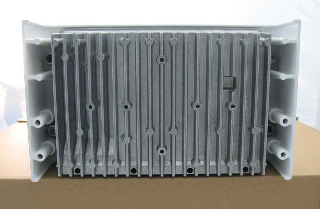
Click to zoom
Application Details
- Equipment Class
- DSS - Part 15 Spread Spectrum Transmitter
- Date of Grant
- Mar 02, 2010
- Application Purpose
- Original Equipment
- Date of Application
- Mar 02, 2010
- Equipment Note
- RFID Reader
- Frequency Range
- 902.70000000 - 927.20000000
- Company
- Feig Electronic GmbH
- Country
- Germany
Documents & Files
Document Text
Text extracted from the exhibit documents filed with the FCC. Open a document above to read the original.
Users Manual
MONTAGE INSTALLATION preliminary public (B) 2010-03-01 M91001-0ed-ID-E.doc OBID i-scan ® ID ISC.LRU3500 ID ISC.LRU3000 (deutsch / english) OBID i-scan ® MontageID ISC.LRU3000 FEIG ELECTRONIC GmbHSeite 2 von 52LRU3000 - Manual.doc D E U T S C H deutsche Version ab Seite 3 english version from page 30 E N G L I S H OBID i-scan ® MontageID ISC.LRU3000 FEIG ELECTRONIC GmbHSeite 3 von 52LRU3000 - Manual.doc D E U T S C H Hinweis © Copyright 2009 by FEIG ELECTRONIC GmbH Lange Strasse 4 D-35781 Weilburg-Waldhausen Tel.: +49 6471 3109-0 http://www.feig.de Alle früheren Ausgaben verlieren mit dieser Ausgabe ihre Gültigkeit. Die Angaben in diesem Dokument können ohne vorherige Ankündigung geändert werden. Weitergabe sowie Vervielfältigung dieses Dokuments, Verwertung und Mitteilung ihres Inhalts sind nicht gestattet, soweit nicht ausdrücklich zugestanden. Zuwiderhandlung verpflichtet zu Schadenersatz. Alle Rechte für den Fall der Patenterteilung oder Gebrauchsmuster-Eintragung vorbehalten. Die Zusammenstellung der Informationen in diesem Dokument erfolgt nach bestem Wissen und Gewissen. FEIG ELECTRONIC GmbH übernimmt keine Gewährleistung für die Richtigkeit und Vollständigkeit der An- gaben in diesem Dokument. Insbesondere kann FEIG ELECTRONIC GmbH nicht für Folgeschäden auf Grund fehlerhafter oder unvollständiger Angaben haftbar gemacht werden. Da sich Fehler trotz aller Bemü- hungen nie vollständig vermeiden lassen, sind wir für Hinweise jederzeit dankbar. Die in diesem Dokument gemachten Installationsempfehlungen gehen von günstigsten Rahmenbedingun- gen aus. FEIG ELECTRONIC GmbH übernimmt weder Gewähr für die einwandfreie Funktion in system- fremden Umgebungen, noch für die Funktion eines Gesamtsystems, welches die in diesem Dokument be- schriebenen Geräte enthält. FEIG ELECTRONIC GmbH weist ausdrücklich darauf hin, dass die in diesem Dokument beschriebenen Geräte nicht für den Einsatz mit oder in medizinischen Geräten oder für Geräte für lebenserhaltende Maß- nahmen konzipiert sind, bei denen ein Fehler eine Gefahr für menschliches Leben oder für die gesundheitli- che Unversehrtheit zur Folge haben kann. Der Applikationsdesigner ist dafür verantwortlich geeignete Maß- nahmen zu ergreifen um Gefahren, Schäden oder Verletzungen zu vermeiden. Geräte, die in diesem Dokument beschrieben werden, dürfen nicht im "Transport Markt" verkauft, benutz, geleast, angeboten oder anderweitig übertragen, exportiert und importiert werden. Als "Transport Markt" sind folgende Anwendungen definiert: (I) Elektronische Maut und Verkehrs Management (ETTM), (II) öffentliche Kraftfahrzeugzulassung, -Registrierung und -Kontrolle (III), Verfolgung von schienengebundenen Lokomoti- ven und Wagons (IV), erdgebundene Managementsysteme für Flughafen Transporte (GTMS) und Taxi Ab- fertigung (V), kostenpflichtige Parksysteme und (VI) Fahrzeug initiierte mobile Bezahlsysteme, bei denen der RFID Transponder bereits bei Auslieferung montiert ist, aber nicht beim Fahrzeughersteller in das Fahrzeug integriert wurde. FEIG ELECTRONIC GmbH übernimmt keine Gewährleistung dafür, dass die in diesem Dokument enthal- tenden Informationen frei von fremden Schutzrechten sind. FEIG ELECTRONIC GmbH erteilt mit diesem Dokument keine Lizenzen auf eigene oder fremde Patente oder andere Schutzrechte. OBID ® und OBID i-scan ® ist ein eingetragenes Warenzeichen der FEIG ELECTRONIC GmbH OBID i-scan ® MontageID ISC.LRU3000 FEIG ELECTRONIC GmbHSeite 4 von 52LRU3000 - Manual.doc D E U T S C H Inhalt 1Leistungsmerkmale der Readerfamilie ID ISC.LRU30006 1.1Leistungsmerkmale.......................................................................................................6 1.2Verfügbare Readertypen...............................................................................................6 1.3Verfügbares Zubehör ....................................................................................................6 2Montage7 3Anschlüsse8 3.1Antennenanschluss ......................................................................................................9 3.1.1 Versorgungsspannung über X1.......................................................................................9 3.2Schnittstellen ...............................................................................................................10 3.2.1 X2 Versorgungsspannung über PoE (Power over Ethernet) an X2 ..............................10 3.2.2 Ethernet-Schnittstelle an X2 (10/100Tbase)..................................................................11 3.2.3 USB – Schnittstelle X3 (Host Kommunikation)..............................................................12 3.2.4 USB – Schnittstelle X4 (WLAN).....................................................................................12 3.2.5 RS232-Schnittstelle X6 .................................................................................................13 3.2.6 RS485-Schnittstelle X6 .................................................................................................14 3.3Digitale Eingänge X5 ...................................................................................................15 3.4Ausgänge .....................................................................................................................17 3.4.1 Digitale Ausgänge X5 ....................................................................................................17 3.4.2 Relais X5 .......................................................................................................................18 4Bedien- und Anzeigeelemente19 4.1Status LEDs .................................................................................................................19 4.2Reset-Taster.................................................................................................................20 4.3Reader Leistungseinstellung .....................................................................................21 4.3.1 EU-Reader (EN 302 20…
Text truncated - open the document above for the full version.
Users Manual
Annex No.5 Page 1 of 53 User manual MONTAGE INSTALLATION preliminary public (B) 2010-02-10 M91001-0ed-ID-E.doc OBID i-scan ® ID ISC.LRU3500 ID ISC.LRU3000 (deutsch / english) OBID i-scan ® MontageID ISC.LRU3000 FEIG ELECTRONIC GmbHSeite 2 von 52LRU3000 - Manual.doc D E U T S C H deutsche Version ab Seite 3 english version from page 30 E N G L I S H OBID i-scan ® MontageID ISC.LRU3000 FEIG ELECTRONIC GmbHSeite 3 von 52LRU3000 - Manual.doc D E U T S C H Hinweis © Copyright 2009 by FEIG ELECTRONIC GmbH Lange Strasse 4 D-35781 Weilburg-Waldhausen Tel.: +49 6471 3109-0 http://www.feig.de Alle früheren Ausgaben verlieren mit dieser Ausgabe ihre Gültigkeit. Die Angaben in diesem Dokument können ohne vorherige Ankündigung geändert werden. Weitergabe sowie Vervielfältigung dieses Dokuments, Verwertung und Mitteilung ihres Inhalts sind nicht gestattet, soweit nicht ausdrücklich zugestanden. Zuwiderhandlung verpflichtet zu Schadenersatz. Alle Rechte für den Fall der Patenterteilung oder Gebrauchsmuster-Eintragung vorbehalten. Die Zusammenstellung der Informationen in diesem Dokument erfolgt nach bestem Wissen und Gewissen. FEIG ELECTRONIC GmbH übernimmt keine Gewährleistung für die Richtigkeit und Vollständigkeit der An- gaben in diesem Dokument. Insbesondere kann FEIG ELECTRONIC GmbH nicht für Folgeschäden auf Grund fehlerhafter oder unvollständiger Angaben haftbar gemacht werden. Da sich Fehler trotz aller Bemü- hungen nie vollständig vermeiden lassen, sind wir für Hinweise jederzeit dankbar. Die in diesem Dokument gemachten Installationsempfehlungen gehen von günstigsten Rahmenbedingun- gen aus. FEIG ELECTRONIC GmbH übernimmt weder Gewähr für die einwandfreie Funktion in system- fremden Umgebungen, noch für die Funktion eines Gesamtsystems, welches die in diesem Dokument be- schriebenen Geräte enthält. FEIG ELECTRONIC GmbH weist ausdrücklich darauf hin, dass die in diesem Dokument beschriebenen Geräte nicht für den Einsatz mit oder in medizinischen Geräten oder für Geräte für lebenserhaltende Maß- nahmen konzipiert sind, bei denen ein Fehler eine Gefahr für menschliches Leben oder für die gesundheitli- che Unversehrtheit zur Folge haben kann. Der Applikationsdesigner ist dafür verantwortlich geeignete Maß- nahmen zu ergreifen um Gefahren, Schäden oder Verletzungen zu vermeiden. Geräte, die in diesem Dokument beschrieben werden, dürfen nicht im "Transport Markt" verkauft, benutz, geleast, angeboten oder anderweitig übertragen, exportiert und importiert werden. Als "Transport Markt" sind folgende Anwendungen definiert: (I) Elektronische Maut und Verkehrs Management (ETTM), (II) öffentliche Kraftfahrzeugzulassung, -Registrierung und -Kontrolle (III), Verfolgung von schienengebundenen Lokomoti- ven und Wagons (IV), erdgebundene Managementsysteme für Flughafen Transporte (GTMS) und Taxi Ab- fertigung (V), kostenpflichtige Parksysteme und (VI) Fahrzeug initiierte mobile Bezahlsysteme, bei denen der RFID Transponder bereits bei Auslieferung montiert ist, aber nicht beim Fahrzeughersteller in das Fahrzeug integriert wurde. FEIG ELECTRONIC GmbH übernimmt keine Gewährleistung dafür, dass die in diesem Dokument enthal- tenden Informationen frei von fremden Schutzrechten sind. FEIG ELECTRONIC GmbH erteilt mit diesem Dokument keine Lizenzen auf eigene oder fremde Patente oder andere Schutzrechte. OBID ® und OBID i-scan ® ist ein eingetragenes Warenzeichen der FEIG ELECTRONIC GmbH OBID i-scan ® MontageID ISC.LRU3000 FEIG ELECTRONIC GmbHSeite 4 von 52LRU3000 - Manual.doc D E U T S C H Inhalt 1Leistungsmerkmale der Readerfamilie ID ISC.LRU30006 1.1Leistungsmerkmale.......................................................................................................6 1.2Verfügbare Readertypen...............................................................................................6 1.3Verfügbares Zubehör ....................................................................................................6 2Montage7 3Anschlüsse8 3.1Antennenanschluss ......................................................................................................9 3.1.1 Versorgungsspannung über X1.......................................................................................9 3.2Schnittstellen ...............................................................................................................10 3.2.1 X2 Versorgungsspannung über PoE (Power over Ethernet) an X2 ..............................10 3.2.2 Ethernet-Schnittstelle an X2 (10/100Tbase)..................................................................11 3.2.3 USB – Schnittstelle X3 (Host Kommunikation)..............................................................12 3.2.4 USB – Schnittstelle X4 (WLAN).....................................................................................12 3.2.5 RS232-Schnittstelle X6 .................................................................................................13 3.2.6 RS485-Schnittstelle X6 .................................................................................................14 3.3Digitale Eingänge X5 ...................................................................................................15 3.4Ausgänge .....................................................................................................................17 3.4.1 Digitale Ausgänge X5 ....................................................................................................17 3.4.2 Relais X5 .......................................................................................................................18 4Bedien- und Anzeigeelemente19 4.1Status LEDs .................................................................................................................19 4.2Reset-Taster.................................................................................................................20 4.3Reader Leistungseinstellung ..............................................................................…
Text truncated - open the document above for the full version.
Cover Letter(s)
m. dudde hochfrequenz-technik Rottland 5a, D-51429 Bergisch-Gladbach DIN EN ISO/IEC 17025 zertifiziert Akkreditiertes Testhaus- Reg.-Nr.: DAT-P-225/96-02 Tel. : +49 22 07 - 96 89 - 0 Fax : +49 22 07 - 96 89 - 20 email: [email protected] www.dudde.com PHOENIX TEST-LAB GmbH Product Certification Königswinkel 10 D 32825 Blomberg Date: 2010-03-01 FCC ID: PJMLRU3000 Subject: Attestation Letter “Declaration of Conformity” Dear Sirs, The products with the above FCC ID are defined as composite device. The transmitter is authorized under the “Certification” procedure. The device is also defined as “PC Periphery” acc to §15.101 Equipment authorization of unintentional radiators, where we hereby declare on behalf of our customer FEIG ELECTRONIC GmbH, that we apply and follow the “Declaration of Conformity” procedure. If you have any questions, please feel free to contact me at the address shown below. Yours sincerely, Andreas Morsbach Assistant Manager m. dudde hochfrequenz-technik Rottland 5a 51429 Bergisch Gladbach Tel.: +49 (0) 2207/9689-18 Fax: +49 (0) 2207/9689-20 E-Mail: [email protected]
Cover Letter(s)
FEIG ELECTRONIC GmbH Lange Straße 4 D-35781 Weilburg-Waldhausen Subject: Request for confidentiality FCC ID: PJMLRU3000 Reference number: Dear FCC TCB, Persuant to 47 CFR Section 0.459(a) & (b), <name applicant> hereby requests non-disclosure and confidential treatment of the following materials submitted in support of FCC certification application for FCC ID: PJM LRU3000 1. Electrical Schematic LRU3000 – Schematic.pdf (25 pages) 2. Block Diagram LRU3000 – Block Diagram.pdf (2 pages) 3. Bill of Material LRU3000 – BOM.pdf (13 pages) 4. Operational Description LRU3000 – Description (2 pages) Above materials contain secrets, proprietary and technical information, which would customarily be quarded from competitors under 47 CFR, section 0.457(d)(2). Disclosure or publication or any portion of this company confidential material to other parties could cause substantial competitive harm and provide unjustified benefits for competitors. <Name applicant> understands that pursuant to 47 CFR section 0.457(d)(1)(ii) disclosure of the applicant and all accompanying documentation will not be made before the date of the grant. Date: 2009-10-27 City: Weilburg-Waldhausen Name of applicant: Dipl.-Ing. Andreas Wennrich Signature: _____________________________
Cover Letter(s)
FEIG ELECTRONIC GmbH - Lange Straße 4 - D-35781 Weilburg-Waldhausen account details: Kreissparkasse Weilburg (Bank sorting code No. 511 519 19) Account-No. 100 451 012 IBAN: DE 38511519190100451012 Dresdner Bank Limburg (Bank sorting code No. 513 800 40) Account-No. 9 367 354 00 IBAN: DE 60 5138 0040 0936 7354 00 Managing Director: Dipl.-Ing. Wolfgang Feig Place of Jurisdiction: Limburg HRB 3178 Sales tax-IdNo. DE 811 460 661 VEK Traffic Detectors TST Control technology OBID ® Object identification your signdate of your messageour signyour correspondency partner / phone directdate AWWennrich / -4682009-10-27 Power of Attorney To: Phoenix Testlab GmbH Name or model type of the Specified Radio Equipment:ID ISC.LRU3500-FCC ID ISC.LRU3000-FCC Applicant’s company name:FEIG ELECTRONIC GmbH Applicant’s company address:Lange Starße 4 D- Weilburg-Waldhausen Applicant’s name:Andreas Wennrich Date and Applicant’s Signature:2010-01-11 __________________ Job Title and Department:Hardware Engineer It is necessary, that the person registered with FCC, signs this form. I hereby authorize the following person as a representative and all rights regarding the application to obtain Type Certification for the Specified Radio Equipment (mentioned above) are delegated. Attorney’s Company name:m. dudde hochfrequenz-technik Attorney’s Company address:Rottland 5 a 51429 Bergisch Gladbach Attorney’s Name:Mr. Andreas Morsbach Mrs. Anja Hittig-Rademacher Date and Attorney’s Signature:_____________________________ Job Title and Department:homologation department
External Photos
Annex No.1 Page 1 of 9 External photographs of the Equipment Under Test Annex No.1 Page 2 of 9 Annex No.1 Page 3 of 9 Annex No.1 Page 4 of 9 Annex No.1 Page 5 of 9 Annex No.1 Page 6 of 9 Annex No.1 Page 7 of 9 Photographs of antennas Annex No.1 Page 8 of 9 Annex No.1 Page 9 of 9
ID Label/Location Info
Annex No.4 Page 1 of 2 Label sample & sketch of label location ID ISC.LRU3500 / ID ISC.LRU3000 FCC ID: PJMLRU3000 FEIG ELECTRONIC GmbH1/1 Label ID ISC.LRU3500-FCC (70 x 32 mm 2 ) Label ID ISC.LRU3000-FCC (70 x 32 mm 2 ) Position of the Label on the case:
Internal Photos
Annex No.2 Page 1 of 8 Internal photographs of the Equipment Under Test Annex No.2 Page 2 of 8 Annex No.2 Page 3 of 8 Annex No.2 Page 4 of 8 Annex No.2 Page 5 of 8 Annex No.2 Page 6 of 8 Annex No.2 Page 7 of 8 Annex No.2 Page 8 of 8
RF Exposure Info
MPE calculation Page 1 of 1 EUT: UHF Long Range Reader ID ISC.LRU 3500 Date of issue: 2010-01-19 m. dudde hochfrequenz-technik Rottland 5a Vers. no. 1.10 D-51429 Bergisch Gladbach Tel.: +49 2207-9689-0 Fax: +49 2207 9689-20 e-mail: [email protected] http://www.dudde.com MPE calculation to the FCC ID: PJMLRU3000 UHF Long Range Reader ID ISC.LRU 3500 These equations are generally accurate in the far field of an antenna but will over predict power density in the near field, where they could be used for making a “worst case” prediction. S = PG/4πR 2 where S = power density ( in appropriate units, e.g. mW/cm2) P = power input to the antenna (in appropriate units e.g. mW) G = power gain of the antenna in the direction of interest relative to the isotropic radiator R = distance to the center of radiation of the antenna (appropriate units e.g. cm) Or S = EIRP/4πR 2 where EIRP = equivalent isotropically radiated power 1 st . Calculation: (Calculated for max. EIRP) EIRP: 35.9 dBm = 3890.5 mW calculated at distance of 20 cm: power density = 3890.5 /4*π*20 2 = 0.774 mW/ cm 2 2 nd . Calculation for estimated safe separation: (Calculated for max. EIRP) EIRP: 35.9 dBm = 3890.5 mW R = √(PG/S4л) = √(3890.5[mW]/0.774 [mW/cm 2 ]4л) minimum estimated safe separation = 22.7 cm Limit: Signature (Technical engineer) Ralf Trepper 0.6 mW/cm 2 is the reference level for general public exposure according to the OET Bulletin 65, Edition 97-01 Table 1.
Test Report
Test report no. 10005914 Page 1 of 52 EUT: UHF Long Range Reader ID ISC.LRU 3500 FCC ID: PJMLRU3000 Date of issue: 2010-01-19 m. dudde hochfrequenz-technik Rottland 5a Vers. no. 1.07 D-51429 Bergisch Gladbach Tel.: +49 2207-9689-0 Fax: +49 2207 9689-20 e-mail: [email protected] http://www.dudde.com DAT-P-225/96-02 Test Report acc. to the relevant standard 47 CFR Part 15 C – Intentional Radiators 47 CFR Part 15 B – Unintentional Radiators Measurement Procedure: ANSI C63.4 - 2003 relating to Feig Electronic GmbH UHF Long Range Reader ID ISC.LRU 3500 Variant: UHF Long Range Reader ID ISC.LRU 3000 Measurement of Radio- Noise Emissions from Low- Voltage Electrical and Electronic Equipment Technical characteristics and test methods for radio equipment in the frequency range 9 kHz to 40 GHz Test report no. 10005914 Page 2 of 52 EUT: UHF Long Range Reader ID ISC.LRU 3500 FCC ID: PJMLRU3000 Date of issue: 2010-01-19 m. dudde hochfrequenz-technik Rottland 5a Vers. no. 1.07 D-51429 Bergisch Gladbach Tel.: +49 2207-9689-0 Fax: +49 2207 9689-20 e-mail: [email protected] http://www.dudde.com Manufacturer’s details Manufacturer FEIG ELECTRONIC GmbH Manufacturer’s grantee code PJM Manufacturer’s address FEIG ELECTRONIC GmbH Lange Str. 4 35781 Weilburg Tel.: +49 (0) 6471 31 09 968 Fax :+49 (0) 6471 31 09 99 Contact person: Andreas Wennrich Email: [email protected] Relevant standard used 47 CFR Part 15C - Intentional Radiators ANSI C63.4-2003 Test Report prepared by Technical engineer Ralf Trepper m.dudde hochfrequenz-technik (laboratory) Rottland 5a 51429 Bergisch Gladbach Germany Phone: +49 2207 96890 Fax: +49 2207 968920 E-mail: [email protected] Equipment Under Test (EUT) Equipment category FHSS Transceiver Trade name FEIG Type designation UHF Long Range Reader ID ISC.LRU3500 Serial no. --- Variants UHF Long Range Reader ID ISC.LRU3000 Test report no. 10005914 Page 3 of 52 EUT: UHF Long Range Reader ID ISC.LRU 3500 FCC ID: PJMLRU3000 Date of issue: 2010-01-19 m. dudde hochfrequenz-technik Rottland 5a Vers. no. 1.07 D-51429 Bergisch Gladbach Tel.: +49 2207-9689-0 Fax: +49 2207 9689-20 e-mail: [email protected] http://www.dudde.com 1. Test results CFR Section Report Chapter Requirements Headline Test result 15.203 11.1 Antenna requirement pass fail n.t. 15.205(a) 11.2 Operation in the restricted bands pass fail n.t. 15.209(a) 11.3 Radiated emissions pass fail n.t. 15.247(a)(1)(i) 11.4 Channel occupancy / bandwidth pass fail n.t. 15.247(b)(2) 11.5 Peak output power pass fail n.t. 15.247(d) 11.6 Out of band emissions pass fail n.t. 15.247(i) 11.7 Radio frequency hazard pass fail n.t. 15.207 11.8 Conducted limits pass fail n.t. Test requirements kept yes no Signature (Technical engineer) Ralf Trepper Signature (Manager) Manfried Dudde Test report no. 10005914 Page 4 of 52 EUT: UHF Long Range Reader ID ISC.LRU 3500 FCC ID: PJMLRU3000 Date of issue: 2010-01-19 m. dudde hochfrequenz-technik Rottland 5a Vers. no. 1.07 D-51429 Bergisch Gladbach Tel.: +49 2207-9689-0 Fax: +49 2207 9689-20 e-mail: [email protected] http://www.dudde.com List of contents Page 1. Test results ................................................................................................................................................... 3 2. Test laboratory ............................................................................................................................................. 6 3. Introduction .................................................................................................................................................. 6 4. Product ......................................................................................................................................................... 7 5. Test schedule ................................................................................................................................................ 7 6. Product and measurement documentation .................................................................................................... 8 7. Observations and comments ......................................................................................................................... 8 8. Summary ...................................................................................................................................................... 8 9. Conclusions ................................................................................................................................................. 9 10. Operation description ................................................................................................................................. 10 11.1 Antenna requirement ................................................................................................................................ 11 11.1.1 Regulation ....................................................................................................................................... 11 11.1.2 Result ............................................................................................................................................... 11 11.2 Operation in the restricted bands ............................................................................................................. 12 11.2.1 Regulation ....................................................................................................................................... 12 11.2.2 Result ............................................................................................................................................... 14 11.3 Radiated emissions .................................................................................................................................. 15 11.3.1 Regulation ....................................................................................................................................... 15 …
Text truncated - open the document above for the full version.
Test Report
Annex No.3 Page 1 of 1 Occupied bandwidth plot
Test Report
Annex No.11 Page 1 of 7 Channel occupancy 50 hopping channels between 902.7 MHz and 927.2 MHz with a channel spacing of 500 kHz Annex No.11 Page 2 of 7 Behavior of the Lowest Channel 902.700 MHz There is one transmit packed every 15 seconds Annex No.11 Page 3 of 7 shortest single hop measured longest single hop measured Annex No.11 Page 4 of 7 Behavior of the Middle Channel 914.700 MHz There is one transmit packed every 15 seconds Annex No.11 Page 5 of 7 shortest single hop measured longest single hop measured Annex No.11 Page 6 of 7 Behavior of the Middle Channel 927.200 MHz There is one transmit packed every 15 seconds Annex No.11 Page 7 of 7 shortest single hop measured longest single hop measured There is one transmit packed every 15 seconds, with a maximum time of occupancy from 292 msec. Therefore the maximum average time of occupancy is: 292 msec * 4/3 time = 389.3 msec.
Test Report
Annex No. 12 Page 1 of 2 Antenna description ID ISC.LRU3500 / ID ISC.LRU3000 FEATURES ¼ ID ISC.ANT.U600/270-FCC: 30° Beam width ¼ ID ISC.ANT.U170/170-FCC: very small and light shape ¼ New design ¼ Circular polarization for optimal reading performance ¼ Optimized for operation in North America ¼ IP 65 for outdoor use UHF RFID Antennas ID ISC.ANT.U170/170-FCC ID ISC.ANT.U270/270-FCC ID ISC.ANT.U600/270-FCC ¼ UHF RFID Antennas FEIG ELECTRONIC reserves the right to change specification without notice at any time. State of information: July 2009. ¼ Order description: ID ISC.ANT.U170/170-FCC ID ISC.ANT.U270/270-FCC ID ISC.ANT.U600/270-FCC ID ISC.ANT.U170/170-FCC ID ISC.ANT.U270/270-FCC ID ISC.ANT.U600/270-FCC Dimensions 170 x 170 x 25 mm 270 x 270 x 57 mm 590 x 270 x 57 mm Housing ASA-ABS ASA-ABS ASA-ABS Color White White White Weight 270 g 1.210 g 2.200 g Protection class IP65 IP65 IP65 Operating frequency 902-928 MHz 900-930 MHz 900-930 MHz Gain 3.5 dBic 8.7 dBic 10.5 dBic 3 dB beam width 85° x 85° 65° x 65° 30° x 65° Polarization circular circular circular Antenna connection SMA socket (50 Ohm) SMA socket (50 Ohm) SMA socket (50 Ohm) Temperature range Operation - 25°C up to 55° C - 25°C up to 55° C - 25°C up to 55° C Storage - 25°C up to 80° C - 25°C up to 80° C - 25°C up to 80° C Available accessories: Antenna cables ID ISC.ANT.C2-A Mounting sets ID ISC.ANT.U170/170-MS ID ISC.ANT.C6-A ID ISC.ANT.U270/270-MS ID ISC.ANT.U600/270-MS Antennas are compatible with any current UHF Reader system. FEATURES ¼ Best performances in each frequency range by specifically optimized EU- and FCC antenna ¼ Two antenna cables available (2m and 6m) ¼ Mounting set for easy installation available UHF RFID Antenna ID ISC.ANT.U250/250-EU/-FCC ¼ SHORT DESCRIPTION TECHNICAL DATA Dimensions (W x H x D) 260 x 260 x 56 mm 10.24 x 10.24 x 2.2 inch Housing Plastic Color Papyrus white (similar RAL9018) Weight approx. 1.050 g Protection class IP 54 Operating frequency EU Antenna 865-868 MHz FCC Antenna 902-928 MHz Gain EU Antenna 9,0 dBic FCC Antenna 8,7 dBic 3 dB beam width 65° x 65° Polarization circular VSWR < 1,5 : 1 Antenna connection SWA socket (50 Ohm) Temperature range Operation –25 °C up to 55 °C Storage –25 °C up to 85 °C Information about the mounting set ID ISC.MS.ANT.U250/250 Maximum clamping range 30 – 60 mm Material Aluminium, steel-galvanized Weight 380 g Orientation Changeable in three directions UHF RFID Antenna ID ISC.ANT.U250/250-EU/-FCC FEIG ELECTRONIC reserves the right to change specification without notice at any time. Last update: August 2009 Applikation mit einem Multiplexer ¼ Order descriptions: ID ISC.ANT.U250/250-EU Antenna UHF ID ISC.ANT.U250/250-FCC Antenna UHF The UHF antennas ID ISC.ANT.U250/250-EU/-FCC are circular polarized antennas for operating frequencies in the UHF ranges 865-868 MHz (EU antenna) and 902-928 MHz (FCC antenna). So the antennas can be used for applications within both released UHF ranges in Europe (865-868 MHz) as well as in North America (902-928 MHz). Due to an integrated multiplexer, the long range readers of the OBID i-scan ® UHF family can be connected with up to four UHF antennas. Due to the antennas ́ circular polarization, transponders can be identified in two different orientations . Available accessories: ID ISC.ANT.C2-A, 2m Antenna cable ID ISC.ANT.C6-A, 6m Antenna cable ID ISC.MS.ANT.U250/250 Mounting set
Test Setup Photos
Annex No.6 Page 1 of 10 Test setup photos Annex No.6 Page 2 of 10 Annex No.6 Page 3 of 10 Annex No.6 Page 4 of 10 Annex No.6 Page 5 of 10 Annex No.6 Page 6 of 10 Annex No.6 Page 7 of 10 Annex No.6 Page 8 of 10 Annex No.6 Page 9 of 10 Annex No.6 Page 10 of 10
Contact Information
Applicant
Elmar Reichwein(Manager)
Test Firm
m. dudde hochfrequenz-technikManfred Dudde
Technical Specifications
| # | Rule Parts | Frequency Range | Power Output |
|---|---|---|---|
| 1 | 15C | 902.7 MHz - 927.2 MHz | 1 W |
Other Applications from Feig Electronic GmbH

PJMPRM103
Feb 25, 2026RFID Reader
Equipment Class
DXX - Part 15 Low Power Communication Device Transmitter
PJMMRM103
Jan 19, 2026RFID Reader
Equipment Class
DXX - Part 15 Low Power Communication Device TransmitterPJMTSTFSAMC
Dec 01, 2024Wireless Safety System for industrial doors - Mobile Unit
Equipment Class
DXX - Part 15 Low Power Communication Device Transmitter
PJMLRM5400
Jun 27, 2023RFID Reader
Equipment Class
DXX - Part 15 Low Power Communication Device Transmitter
PJMMRU102A
Jul 07, 2021RFID Reader
Equipment Class
DSS - Part 15 Spread Spectrum Transmitter