PJMM02M8RFID Reader
Feig Electronic GmbH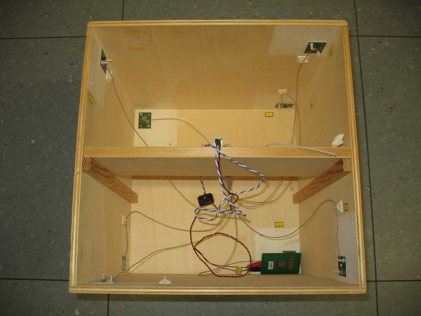
Click to zoom
Application Details
- Equipment Class
- DXX - Part 15 Low Power Communication Device Transmitter
- Date of Grant
- Jun 08, 2020
- Application Purpose
- Original Equipment
- Date of Application
- Jun 08, 2020
- Equipment Note
- RFID Reader
- Frequency Range
- 13.56000000 - 13.56000000
- Company
- Feig Electronic GmbH
- Country
- Germany
Documents & Files
Document Text
Text extracted from the exhibit documents filed with the FCC. Open a document above to read the original.
Users Manual
INSTALLATION MANUAL final – public (B) 2020-06-03 – M02M8-IM-e _02.doc ID ISC.M02.M8 IDENTIFICATION Installation ID ISC.M02.M8 FEIG ELECTRONIC GmbH Page 2 of 16 M02M8-IM-e_02.doc Note Copyright by FEIG ELECTRONIC GmbH Lange Strasse 4 D-35781 Weilburg Tel.: +49 6471 3109-0 http://www.feig.de With the edition of this document, all previous editions become void. Indications made in this manual may be changed without previous notice. The reproduction, distribution and utilization of this document as well as the communication of its contents to others without express authorization is prohibited. Offenders will be held liable for the payment of damages. All rights reserved in the event of the grant of a patent, utility model or design. Composition of the information in this document has been done to the best of our knowledge. FEIG ELECTRONIC GmbH does not guarantee the correctness and completeness of the details given in this manual and may not be held liable for damages ensuing from incorrect or incomplete information. Since, despite all our efforts, errors may not be completely avoided, we are always grateful for your useful tips. The instructions given in this manual are based on advantageous boundary conditions. FEIG ELECTRONIC GmbH does not give any guarantee promise for perfect function in cross environments and does not give any guaranty for the functionality of the complete system which incorporates the subject of this document. FEIG ELECTRONIC call explicit attention that devices which are subject of this document are not designed with components and testing methods for a level of reliability suitable for use in or in connection with surgical implants or as critical components in any life support systems whose failure to perform can reasonably be expected to cause significant injury to a human. To avoid damage, injury, or death, the user or application designer must take reasonably prudent steps to protect against system failures. FEIG ELECTRONIC GmbH assumes no responsibility for the use of any information contained in this document and makes no representation that they free of patent infringement. FEIG ELECTRONIC GmbH does not convey any license under its patent rights nor the rights of others. All brand names, trademarks or logos are property of their respective owners. IDENTIFICATION Installation ID ISC.M02.M8 FEIG ELECTRONIC GmbH Page 3 of 16 M02M8-IM-e_02.doc Content ID ISC.M02.M8 1 1 Safety Instructions / Warning - Read before start-up ! 4 2 Performance Characteristics of the ID ISC.M02.M8 Reader Module 5 2.1 Performance Characteristics ................................................................................... 5 2.2 Available module ...................................................................................................... 5 2.3 Available Accessories .............................................................................................. 5 3 Installation and wiring 6 3.1 Dimensions ............................................................................................................... 6 3.2 Wiring ......................................................................................................................... 7 3.2.1 Supply voltage ............................................................................................................ 7 3.2.2 RS232-LVTTL-Interface (3,3V) ................................................................................... 8 3.2.3 Connection of the external antennas .......................................................................... 9 3.3 Installation notes .................................................................................................... 10 3.3.1 Mounting ................................................................................................................... 10 3.3.2 Influence ................................................................................................................... 10 3.3.3 EMC effects on cables .............................................................................................. 11 3.3.4 EMC effects from magnetic fields ............................................................................. 11 4 Technical Data 12 51. Approvals 14 5.11.1. Europa (CE) ............................................................................................................ 14 5.21.2. USA (FCC) and Canada (IC) .................................................................................. 15 IDENTIFICATION Installation ID ISC.M02.M8 FEIG ELECTRONIC GmbH Page 4 of 16 M02M8-IM-e_02.doc 1 Safety Instructions / Warning - Read before start-up ! The device may only be used for the intended purpose designed by for the manufacturer. The operation manual should be conveniently kept available at all times for each user. Unauthorised changes and the use of spare parts and additional devices which have not been sold or recommended by the manufacturer may cause fire, electric shocks or injuries. Such unauthorised measures shall exclude any liability by the manufacturer. The liability-prescriptions of the manufacturer in the issue valid at the time of purchase are valid for the device. The manufacturer shall not be held legally responsible for inaccuracies, errors, or omissions in the manual or automatically set parameters for a device or for an incorrect application of a device. Repairs may only be executed by the manufacturer. Installation, operation, and maintenance procedures should only be carried out by qualified personnel. Use of the device and its installation must be in accordance with national legal requirements and local electrical codes . When working on devices the valid safety regulations must be observed. The reader module is a limited module. The HF Reader IC has no internal shielding. The module is designed for installation in electronic devices. (e.g. printers, terminals, hand scanners, etc.) Care must be taken to en…
Text truncated - open the document above for the full version.
Cover Letter(s)
CONFIDENTIALITY REQUEST for Certification Service in the USA Federal Communication Commission Equipment Authorization Division, Application Processing Branch 7435 Oakland Mills Road Columbia, MD 21048 TO WHOM IT MAY CONCERN Pursuant to Paragraphs §0.457 and 0.459 of the Commission’s Rules (47 C.F.R.) and Section §552(b)(4) of the Freedom of Information Act, we request short term confidentiality for the following product: FCC ID: PJMM02M8 Check your GC here . Click "Grantee Search" For the product stated above, we request that the following information be held confidential: External and Internal Photographs, Test Setup Photos, User Manual. We request this confidentiality on the basis of ensuring that business sensitive information remains confidential until the actual marketing of our new device, which is planned for: 31.08.2020 If you have any questions, please feel free to contact me at the address shown below. Sincerely, Company Name: FEIG ELECTRONIC GmbH Phone: +49 6471 / 31 09 435 Company Address: Lange Straße 4 Fax: +49 6471 / 31 09 99 35781 Weilburg (Germany) E-mail: [email protected] Contact Name: Bernhard Schüßler Signature: Signature Date: 29.05.2020 Document Version 1.0 2019-07-01
Cover Letter(s)
CONFIDENTIALITY REQUEST for Certification Service in the USA Federal Communication Commission Equipment Authorization Division, Application Processing Branch 7435 Oakland Mills Road Columbia, MD 21048 TO WHOM IT MAY CONCERN Pursuant to Paragraphs §0.457 and 0.459 of the Commission’s Rules (47 C.F.R.) and Section §552(b)(4) of the Freedom of Information Act, we request confidentiality for the following product: FCC ID: PJMM02M8 For the product stated above, we request permanent confidentiality for exhibits which contain Operational Description, Block Diagram, Schematics, Parts Lists or Tune Up Information. The above exhibits contain our trade secrets and proprietary information that could be of benefit to our competitors. If you have any questions, please feel free to contact me at the address shown below. Sincerely, Company Name: FEIG ELECTRONIC GmbH Phone: +49 6471 / 31 09 435 Company Address: Lange Straße 4 Fax: +49 6471 / 31 09 99 35781 Weilburg (Germany) E-mail: [email protected] Contact Name: Bernhard Schüßler Signature: Signature Date: 13.05.2020 Document Version 1.0 2019-07-01
Cover Letter(s)
RSP‐100, Issue 11, Annex D Modular Approval Attestation Federal Communication Commission Equipment Authorization Division, Application Processing Branch 7435 Oakland Mills Road Columbia, MD 21048 Certification and Engineering Bureau Innovation, Science and Economic Development Canada Spectrum Engineering Branch 3701 Carling Avenue, Building 94 Ottawa, Ontario K2H 8S2 Subject: FCC / ISED Modular Approval Statement Only applicable for ISED certification: TO WHOM IT MAY CONCERN Pursuant to Paragraphs RSP‐100, Issue 11 and CFR § 15.212, we herewith declare for our module. If you have any questions, please feel free to contact us at the address shown below Best regards, INFO for applicant: Limited Modolar Approval (LMA) may be granted when one or more of the requirements in the table above cannot be demonstrated. LMA will also be issued in those instances where applicants can demonstrate that they will retain control over the final installation of the device, such that compliance of the end product is assured. In such cases, an operating condition on the LMA for the module must state that the module is only approved for use when installed in devices produced by a specific manufacturer. When LMA is sought, the application for equipment certification must specifically state how control of the end product, into which the module will be installed, will be maintained, such that full compliance of the end product is always ensured.
External Photos
Photo ID ISC.M02.M8 1 / 2 FCC ID: PJMM02M8 IC: 6633A-M02M8 Date: 15.04.2020 Reader ID ISC.M02.M8 Top side Bottom side Photo ID ISC.M02.M8 2 / 2 FCC ID: PJMM02M8 IC: 6633A-M02M8 Date: 15.04.2020 Antenna ID ISC.ANT40/30 HF Cable Top side Bottom side
External Photos
Annex A 1-0188/20-01-01_AnnexA External photos of the Equipment Under Test This addendum is electronically signed and valid without handwritten signature. For verification of the electronic signatures, the public keys can be requested at the testing laboratory. Document authorized: Tobias Wittenmeier Testing Manager Radio Communications & EMC CTC advanced GmbHUntertuerkheimer Str. 6-10 66117 Saarbruecken / Germany Phone: +49 681 5 98 - 0 Fax: +49 681 5 98 - 9075 web: ctcadvanced.com e-mail: [email protected] Photos Photo 1 Photo 2 2020-04-02Document No. 1-0188/20-01-01_AnnexA2/5 Photo 3 Photo 4 2020-04-02Document No. 1-0188/20-01-01_AnnexA3/5 Photo 5 2020-04-02Document No. 1-0188/20-01-01_AnnexA4/5 Document history VersionApplied changesDate of release initial release2020-04-02 - END OF DOCUMENT - 2020-04-02Document No. 1-0188/20-01-01_AnnexA5/5
ID Label/Location Info
Label ID ISC.M02.M8 1 / 1 FCC ID: PJMM02M8 IC: 6633A-M02M8 Date : 29.05.2020 ID ISC.M02.M8
Internal Photos
Annex B 1-0188/20-01-01_AnnexB Internal photos of the Equipment Under Test This addendum is electronically signed and valid without handwritten signature. For verification of the electronic signatures, the public keys can be requested at the testing laboratory. Document authorized: Tobias Wittenmeier Testing Manager Radio Communications & EMC CTC advanced GmbHUntertuerkheimer Str. 6-10 66117 Saarbruecken / Germany Phone: +49 681 5 98 - 0 Fax: +49 681 5 98 - 9075 web: ctcadvanced.com e-mail: [email protected] Photos Photo 1 Photo 2 2020-04-02Document No. 1-0188/20-01-01_AnnexB2/4 Photo 3 Photo 4 2020-04-02Document No. 1-0188/20-01-01_AnnexB3/4 Document history VersionApplied changesDate of release initial release2020-04-02 - END OF DOCUMENT - 2020-04-02Document No. 1-0188/20-01-01_AnnexB4/4
Internal Photos
Photo ID ISC.M02.M8 1 / 2 FCC ID: PJMM02M8 IC: 6633A-M02M8 Date: 29.05.2020 Reader ID ISC.M02.M8 Top side Bottom side Top side no shielding Photo ID ISC.M02.M8 2 / 2 FCC ID: PJMM02M8 IC: 6633A-M02M8 Date: 29.05.2020 Antenna ID ISC.ANT40/30 HF Cable Top side Bottom side
Test Report
BNetzA-CAB-02/21-102 TEST REPORT Test report no.: 1-0188/20-01-02 Testing laboratory Applicant CTC advanced GmbH Untertuerkheimer Strasse 6 – 10 66117 Saarbruecken / Germany Phone: + 49 681 5 98 - 0 Fax: + 49 681 5 98 - 9075 Internet: http://www.ctcadvanced.com e-mail: [email protected] Accredited Testing Laboratory: The testing laboratory (area of testing) is accredited according to DIN EN ISO/IEC 17025 (2005) by the Deutsche Akkreditierungsstelle GmbH (DAkkS) The accreditation is valid for the scope of testing procedures as stated in the accreditation certificate starting with the registration number: D-PL-12076-01. FEIG ELECTRONIC GmbH Lange Str. 4 35781 Weilburg / GERMANY Phone: +49 6471 31 09-0 Contact: Bernhard Schüßler e-mail: [email protected] Phone: +49 6471 310-9435 Manufacturer FEIG ELECTRONIC GmbH Lange Str. 4 35781 Weilburg / GERMANY Test standard/s FCC - Title 47 CFR Part 15 FCC - Title 47 of the Code of Federal Regulations; Chapter I; Part 15 - Radio frequency devices RSS - 210 Issue 10 Spectrum Management and Telecommunications Radio Standards Specification - Licence-Exempt Radio Apparatus: Category I Equipment For further applied test standards please refer to section 3 of this test report. Test Item Kind of test item: RFID Reader Model name: ID ISC.M02.M8 FCC ID: PJMM02M8 IC: 6633A-M02M8 Frequency: 13.56 MHz Technology tested: RFID Antenna: 8 external PBC loop coil antennas Power supply: 20.4 V to 27.6 V DC by external power supply Temperature range: -20°C to +70°C This test report is electronically signed and valid without handwritten signature. For verification of the electronic signatures, the public keys can be requested at the testing laboratory. Test report authorized: Test performed: Christoph Schneider Tobias Wittenmeier Lab Manager Testing Manager Radio Communications Radio Communications Test report no.: 1-0188/20-01-02 © CTC advanced GmbH Page 2 of 28 1 Table of contents 1 Table of contents ............................................................................................................................................ 2 2 General information ....................................................................................................................................... 3 2.1 Notes and disclaimer .......................................................................................................................... 3 2.2 Application details ............................................................................................................................... 3 2.3 Test laboratories sub-contracted ...................................................................................................... 3 3 Test standard/s, references and accreditations .......................................................................................... 4 4 Test environment ............................................................................................................................................ 5 5 Test item .......................................................................................................................................................... 5 5.1 General description ............................................................................................................................. 5 5.2 Additional information ........................................................................................................................ 5 6 Description of the test setup ......................................................................................................................... 6 6.1 Shielded semi anechoic chamber ...................................................................................................... 7 6.2 Shielded fully anechoic chamber ...................................................................................................... 8 6.3 AC conducted ...................................................................................................................................... 9 6.4 RF measurements normal and extreme conditions ....................................................................... 10 7 Sequence of testing ..................................................................................................................................... 11 7.1 Sequence of testing radiated spurious 9 kHz to 30 MHz ............................................................... 11 7.2 Sequence of testing radiated spurious 30 MHz to 1 GHz .............................................................. 12 8 Measurement uncertainty ............................................................................................................................ 13 9 Summary of measurement results ............................................................................................................. 14 10 Additional comments ............................................................................................................................... 14 11 Measurement results ................................................................................................................................ 15 11.1 Occupied bandwidth ...................................................................................................................... 15 11.2 Field strength of the fundamental ................................................................................................ 17 11.3 Field strength of the harmonics and spurious ........................................................................... 18 11.4 Conducted limits ............................................................................................................................ 21 11.5 Frequency error ............................................................................................................................. 24 12 Observations ...............................................…
Text truncated - open the document above for the full version.
Test Setup Photos
Annex D 1-0188/20-01-01_AnnexD Setup photos of the Equipment Under Test This addendum is electronically signed and valid without handwritten signature. For verification of the electronic signatures, the public keys can be requested at the testing laboratory. Document authorized: Christoph Schneider Lab Manager Radio Communications & EMC CTC advanced GmbHUntertuerkheimer Str. 6-10 66117 Saarbruecken / Germany Phone: +49 681 5 98 - 0 Fax: +49 681 5 98 - 9075 web: ctcadvanced.com e-mail: [email protected] Photos Photo 1 Photo 2 2020-04-03Document No. 1-0188/20-01-01_AnnexD2/7 Photo 3 Photo 4 2020-04-03Document No. 1-0188/20-01-01_AnnexD3/7 Photo 5 Photo 6 2020-04-03Document No. 1-0188/20-01-01_AnnexD4/7 Photo 7 Photo 8 2020-04-03Document No. 1-0188/20-01-01_AnnexD5/7 Photo 9 2020-04-03Document No. 1-0188/20-01-01_AnnexD6/7 Document history VersionApplied changesDate of release initial release2020-04-03 - END OF DOCUMENT - 2020-04-03Document No. 1-0188/20-01-01_AnnexD7/7
Contact Information
Applicant
Elmar Reichwein(Manager)
Test Firm
cetecom advanced GmbHGerald Schmidt
Technical Specifications
| # | Rule Parts | Frequency Range | Power Output |
|---|---|---|---|
| 1 | 15C | 13.56 MHz - 13.56 MHz | - |
Other Applications from Feig Electronic GmbH

PJMPRM103
Feb 25, 2026RFID Reader
Equipment Class
DXX - Part 15 Low Power Communication Device Transmitter
PJMMRM103
Jan 19, 2026RFID Reader
Equipment Class
DXX - Part 15 Low Power Communication Device TransmitterPJMTSTFSAMC
Dec 01, 2024Wireless Safety System for industrial doors - Mobile Unit
Equipment Class
DXX - Part 15 Low Power Communication Device Transmitter
PJMLRM5400
Jun 27, 2023RFID Reader
Equipment Class
DXX - Part 15 Low Power Communication Device Transmitter
PJMMRU102A
Jul 07, 2021RFID Reader
Equipment Class
DSS - Part 15 Spread Spectrum Transmitter