PJMMLL02Inductive Tag Reader
Feig Electronic GmbH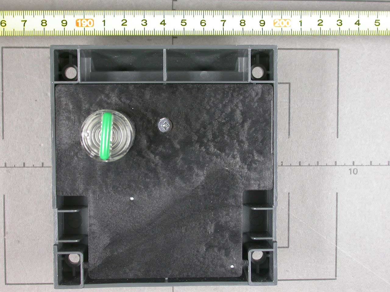
Click to zoom
Application Details
- Equipment Class
- DXT - Part 15 Low Power Transceiver, Rx Verified
- Date of Grant
- Nov 16, 2004
- Application Purpose
- Original Equipment
- Date of Application
- Nov 16, 2004
- Equipment Note
- Inductive Tag Reader
- Frequency Range
- 0.12500000 - 0.12500000
- Company
- Feig Electronic GmbH
- Country
- Germany
Documents & Files
Document Text
Text extracted from the exhibit documents filed with the FCC. Open a document above to read the original.
Users Manual
INSTALLATION final public 2004-10-06 megalock-l-manual.DOC OBID ® Cabinet Lock megalock-l up from Firmware 4.00 (with real time clock) (1) (2) Fig. 1: megalock-l layout right (layout left = mirror image) (1) Recommended door hole diameter 23 mm (2) max. door thickness 21.5 mm OBID ® megalock-lInstallation FEIG ELECTRONIC GmbHPage 2 of 14megalock-l-manual.DOC Note Copyright 1998 - 2004 by FEIG ELECTRONIC GmbH Lange Strasse 4 D-35781 Weilburg-Waldhausen Tel.: +49 6471 3109-0 http://www.feig.de With the edition of this document, all previous editions become void. Indications made in this manual may be changed without previous notice. Copying of this document, and giving it to others and the use or communication of the contents thereof are forbidden without express authority. Offenders are liable to the payment of damages. All rights are reserved in the event of the grant of a patent or the registration of a utility model or design. Composition of the information in this document has been done to the best of our knowledge. FEIG ELECTRONIC GmbH does not guarantee the correctness and completeness of the details given in this manual and may not be held liable for damages ensuing from incorrect or incomplete information. Since, despite all our efforts, errors may not be completely avoided, we are always grateful for your useful tips. The instructions given in this manual are based on advantageous boundary conditions. FEIG ELECTRONIC GmbH does not give any guarantee promise for perfect function in cross environments. FEIG ELECTRONIC GmbH assumes no responsibility for the use of any information contained in this document and makes no representation that they free of patent infringement. FEIG ELECTRONIC GmbH does not convey any license under its patent rights nor the rights of others. OBID ® is a registered trademark of FEIG ELECTRONIC GmbH. OBID ® megalock-lInstallation FEIG ELECTRONIC GmbHPage 3 of 14megalock-l-manual.DOC Contents 1. Safety and warning notices – read before commissioning............................................4 2. Basic functions of the megalock-l..........................................................................................5 2.1. Locking the megalock-l.........................................................................................................5 2.2. Unlocking the megalock-l......................................................................................................5 3. Installation....................................................................................................................................6 4. Start-up procedure....................................................................................................................6 4.1. Function testing with the "TestKey"......................................................................................6 4.2. Configuring the megalock-l with the "SetupKey"...............................................................7 4.3. Configuring for standard/daylight saving time "DSTKey"..................................................8 4.4. . Setting time of day and date "ClockSetKey".....................................................................8 5. Resetting a megalock-l with the "ResetKey"....................................................................10 6. Replacing a megalock-l...........................................................................................................10 7. Battery.........................................................................................................................................11 7.1. Battery replacement.............................................................................................................11 8. Service / Maintenance.............................................................................................................11 ANNEX A Technical Data............................................................................................................12 ANNEX B:........................................................................................................................................13 Europe (CE)..................................................................................................................................13 USA (FCC)....................................................................................................................................13 ANHANG C: LED Blink-Codes...................................................................................................14 OBID ® megalock-lInstallation FEIG ELECTRONIC GmbHPage 4 of 14megalock-l-manual.DOC 1. Safety and warning notices – read before commissioning • The device may only be used for the purpose intended by the manufacturer. • The operating instructions have to be handed out to every user and kept in an easily accessible place. • Unacceptable changes as well as the use of spare parts and special features which are not sold or recommended by the manufacturer, may cause fire, electric shocks and injuries. Therefore, such measures lead to nonliability of the manufacturer and a lapse of all warranty claims. • The appliance is subject to the manufacturer’s guarantee regulations in the version valid at the time of purchase. We cannot be held liable for improper or faulty manual or automatic adjust- ment of parameters resp. improper use of the appliance. • Repair work may only be carried out by the manufacturer. • The user has to make sure that the appliance is installed and operated according to the techni- cal rules of the country of installation as well as other regional regulations. OBID ® megalock-lInstallation FEIG ELECTRONIC GmbHPage 5 of 14megalock-l-manual.DOC 2. Basic functions of the megalock-l (1) Rotary knob: With integrated LED display (red / green) and antenna for exchange between megalock-l and megaKey. (2) Battery compartment: Use special screwdriver to open (Type: ID MS.SSD-A). 2.1. Loc…
Text truncated - open the document above for the full version.
Cover Letter(s)
Request for Confidentiality 15 November 2004 PHOENIX TEST-LAB GmbH Kˆnigswinkel 10 D32825 Blomberg Germany RE: Certification Application FCC ID: PJMMLL02 Please be advised that the following information is to be held confidential on behalf of FEIG ELECTRONIC GmbH • Schematics • Parts Lists • Block Diagram • Technical Description The application contains technical information which FEIG ELECTRONIC GmbH deems to be trade secrets and proprietary. If made public, the information might be used to the disadvantage of the applicant in the market place. Thank you for your attention to this matter. Signatory
External Photos
EMV-Pr ̧fzentrum EMI/EMC-Testcenter FCC ID PJMMLL02 EMV-Pr ̧fzentrum EMI/EMC-Testcenter FCC ID PJMMLL02 FCC ID PJMMLL02 FCC ID PJMMLL02 FCC ID PJMMLL02 FCC ID PJMMLL02
ID Label/Location Info
EMV-Pr ̧fzentrum EMI/EMC-Testcenter FCC ID PJMMLL02 Photo No. 1 Front of unit
Internal Photos
EMV-Pr ̧fzentrum EMI/EMC-Testcenter FCC ID PJMMLL02 EMV-Pr ̧fzentrum EMI/EMC-Testcenter FCC ID PJMMLL02 EMV-Pr ̧fzentrum EMI/EMC-Testcenter FCC ID PJMMLL02 EMV-Pr ̧fzentrum EMI/EMC-Testcenter FCC ID PJMMLL02 EMV-Pr ̧fzentrum EMI/EMC-Testcenter FCC ID PJMMLL02
Test Report
Senton GmbH Aeussere Fruehlingstrasse 45 D-94315 Straubing Note: The test data of this report is related only to the individual item which has been tested. This report shall not be reproduced except in full extent without the written approval of the testing laboratory. Test Report No. 50602-40686-3 (Edition 1) Page 1 of 26 Pages Straubing, October 28, 2004 T E S T - R E P O R T No. 50602-40686-3 for megalock-I Electronic Locking Lock Applicant: FEIG ELECTRONIC GmbH Test Specifications: FCC Code of Federal Regulations, CFR 47, Part 15, Sections 15.205, 15.207 and 15.209 Industry Canada Radio Standards Specification RSS-210 Issue 5, Sections 6.2.1, 6.3 and 6.6 (Category I Equipment) Senton GmbH Aeussere Fruehlingstrasse 45 D-94315 Straubing Test Report No. 50602-40686-3 (Edition 1) Page 2 of 26 Pages Table of Contents 1 Description of the Equipment Under Test (EUT) ........................................................ 3 2 Administrative Data..................................................................................................... 4 3 Identification of the Test Laboratory ........................................................................... 5 4 Summary .................................................................................................................... 6 5 Operation Mode and Configuration of EUT................................................................. 7 6 Measuring Methods .................................................................................................... 8 6.1 Conducted AC powerline emission....................................................................... 8 6.2 Radiated Emission Measurement 9 kHz ñ 30 MHz .............................................. 9 6.3 Radiated emission in Fully Anechoic Room ....................................................... 11 6.4 Radiated emission at Open Field Test Site ........................................................ 13 7 Photographs Taken During Testing .......................................................................... 14 8 List of Measurements ............................................................................................... 18 9 Referenced Regulations ........................................................................................... 25 10 Charts taken during testing ....................................................................................... 26 Senton GmbH Aeussere Fruehlingstrasse 45 D-94315 Straubing Test Report No. 50602-40686-3 (Edition 1) Page 3 of 26 Pages 1 Description of the Equipment Under Test (EUT) General data of EUT Type designation 1 : megalock-I Parts 2 : --- Serial number(s): 01 Manufacturer: FEIG ELECTRONIC GmbH Type of equipment: Electronic Locking Lock Version: As delivered FCC ID: PJMMLL02 Additional parts/accessories: Tag 04FEBOH47 Technical data of EUT Application frequency range: Not applicable 3 Frequency range: 125 kHz Operating frequency: 125 kHz Type of modulation: ASK Pulse train: 373 ms Pulse width: 65.4 ms Number of RF-channels: 1 Channel spacing: Not applicable Class of emission: 5k00A1D Type of antenna: Coil antenna Size/length of antenna: Dimensions of coil: 15 x 17 x 7 mm Number of loops: 280 Type of power supply: Battery supply Specifications for power supply: nominal voltage: 6.0 V minimum voltage: 5.5 V maximum voltage: 6.0 V nominal frequency: --- Hz 1 Type designation of the system if EUT consists of more than one part. 2 Type designations of the parts of the system, if applicable. 3 General requirements according to CFR 47 Part 15 section 15.209 apply. Senton GmbH Aeussere Fruehlingstrasse 45 D-94315 Straubing Test Report No. 50602-40686-3 (Edition 1) Page 4 of 26 Pages 2 Administrative Data Application details Applicant (full address): FEIG ELECTRONIC GmbH Lange Strafle 4 D-35781 Weilburg-Waldhausen Germany Contact person: Mr. Bernhard Sch ̧fller Contract identification: --- Receipt of EUT: October 4, 2004 Date(s) of test: October 2004 Note(s): --- Report details Report number: 50602-40686-3 Edition: 1 Issue date: October 28, 2004 Senton GmbH Aeussere Fruehlingstrasse 45 D-94315 Straubing Test Report No. 50602-40686-3 (Edition 1) Page 5 of 26 Pages 3 Identification of the Test Laboratory Details of the Test Laboratory Company name: Senton GmbH EMI/EMC Test Center Address: Aeussere Fruehlingstrasse 45 D-94315 Straubing Germany Laboratory Accreditation: DAR-Registration No. DAT-P-171/94-02 FCC Test Site registration number 90926 Industry Canada Test site registration: IC 3050 Contact person: Mr. Johann Roidt Phone: (+49) (0)9421 5522-0 Fax: (+49) (0)9421 5522-99 Senton GmbH Aeussere Fruehlingstrasse 45 D-94315 Straubing Test Report No. 50602-40686-3 (Edition 1) Page 6 of 26 Pages 4 Summary Summary of test results The tested sample complies with the requirements set forth in the Code of Federal Regulations CFR 47, Part 15, Sections 15.205, 15.207 and 15.209 of the Federal Communication Commission (FCC) and the Radio Standards Specification RSS-210 Issue 5, Sections 6.2.1, 6.3 and 6.6 (Category I Equipment) of Industry Canada (IC). Personnel involved in this report Laboratory Manager: Mr. Johann Roidt Responsible for testing: Mr. Martin Steindl Responsible for test report: Mr. Martin Steindl Senton GmbH Aeussere Fruehlingstrasse 45 D-94315 Straubing Test Report No. 50602-40686-3 (Edition 1) Page 7 of 26 Pages 5 Operation Mode and Configuration of EUT Operation Mode Reading transponder continuously. Configuration of EUT EUT is configured to transmit continuously, when a transponder is found within 5 seconds after activation. List of ports and cables Port Description Classification 4 Cable type Cable length Not Applicable List of devices connected to EUT Item Description Type Designation Serial no. or ID Manufacturer Not Applicable 4 Ports shall be classified as ac power, dc power or signal/control port Senton GmbH Aeussere Fruehlingstrasse 45 D-94315 Straubing Test Report No. 50602-40686-3 (Edition 1) Page …
Text truncated - open the document above for the full version.
Test Setup Photos
Senton GmbH Aeussere Fruehlingstrasse 45 D-94315 Straubing Test Report No. 50602-40686-3 (Edition 1) Page 15 of 26 Pages Test setup for radiated emission test (fully anechoic room) Senton GmbH Aeussere Fruehlingstrasse 45 D-94315 Straubing Test Report No. 50602-40686-3 (Edition 1) Page 16 of 26 Pages Test setup for radiated emission test (open field test site) Senton GmbH Aeussere Fruehlingstrasse 45 D-94315 Straubing Test Report No. 50602-40686-3 (Edition 1) Page 17 of 26 Pages
Contact Information
Applicant
Elmar Reichwein(Manager)
Technical Contact
Senton GmbHJohann Roidt
[email protected]+49 9421 55 22 13
Aeussere Fruehlingstrasse 45 · Straubing · Germany
Non-Technical Contact
Senton GmbHJohann Roidt
[email protected]+49 9421 55 22 13
Test Firm
TUV SUD Product Service GmbH PS-EMC-STRRainer Heller
Technical Specifications
| # | Rule Parts | Frequency Range | Power Output |
|---|---|---|---|
| 1 | 15C | 0.125 MHz - 0.125 MHz | - |
Other Applications from Feig Electronic GmbH

PJMPRM103
Feb 25, 2026RFID Reader
Equipment Class
DXX - Part 15 Low Power Communication Device Transmitter
PJMMRM103
Jan 19, 2026RFID Reader
Equipment Class
DXX - Part 15 Low Power Communication Device TransmitterPJMTSTFSAMC
Dec 01, 2024Wireless Safety System for industrial doors - Mobile Unit
Equipment Class
DXX - Part 15 Low Power Communication Device Transmitter
PJMLRM5400
Jun 27, 2023RFID Reader
Equipment Class
DXX - Part 15 Low Power Communication Device Transmitter
PJMMRU102A
Jul 07, 2021RFID Reader
Equipment Class
DSS - Part 15 Spread Spectrum Transmitter