PJMMR102RFID Reader
Feig Electronic GmbH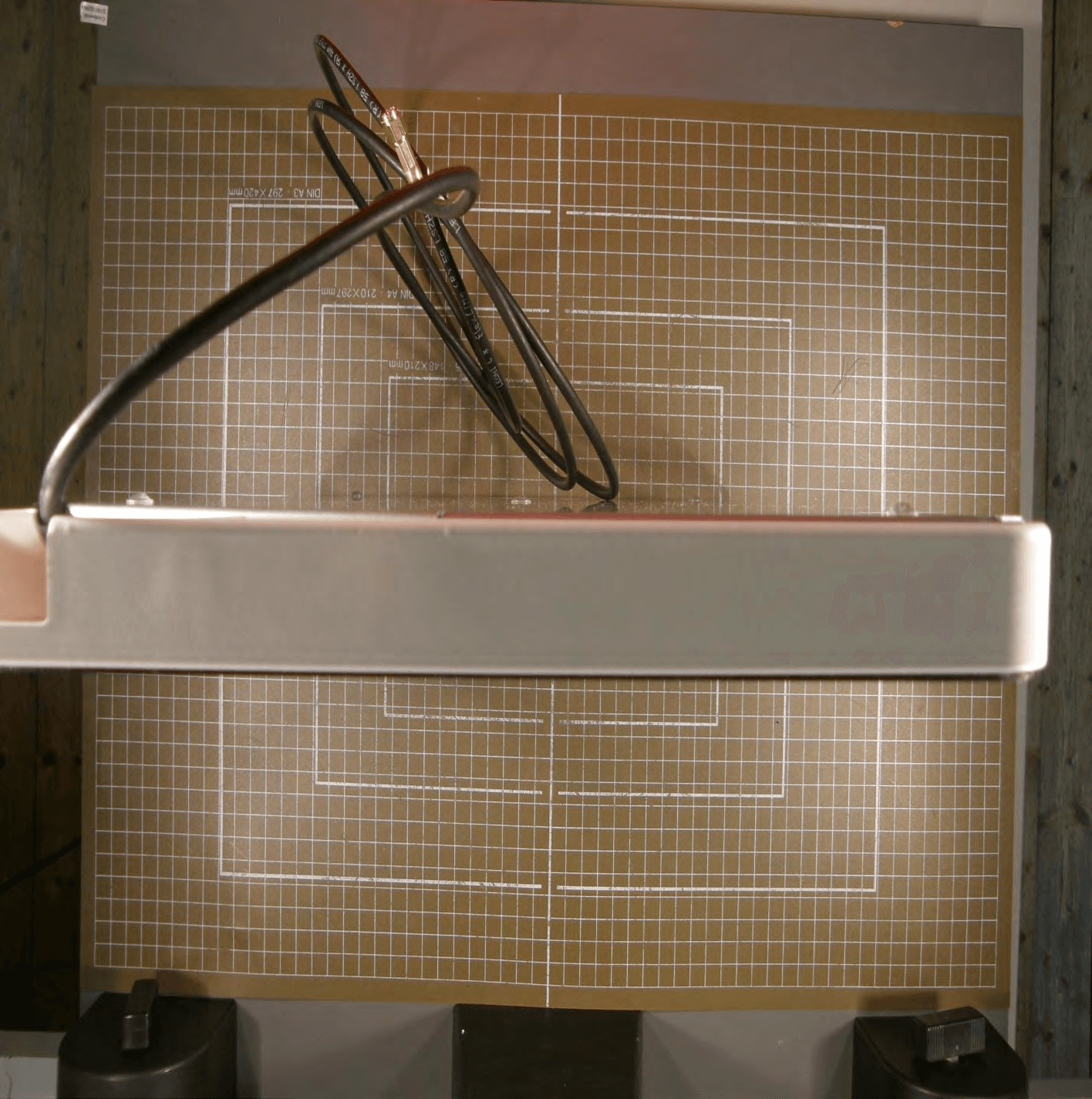
Click to zoom
Application Details
- Equipment Class
- DXX - Part 15 Low Power Communication Device Transmitter
- Date of Grant
- Sep 14, 2011
- Application Purpose
- Original Equipment
- Date of Application
- Sep 13, 2011
- Equipment Note
- RFID Reader
- Frequency Range
- 13.56000000 - 13.56000000
- Company
- Feig Electronic GmbH
- Country
- Germany
Documents & Files
Document Text
Text extracted from the exhibit documents filed with the FCC. Open a document above to read the original.
Users Manual
State: 2010-03-01 Vers. no.: 1.10 m. dudde hochfrequenz-technik Rottland 5a D-51429 Bergisch Gladbach/ Germany Tel. +49 2207-96890 Fax +49 2207 968920 Annex no. 5 Functional Description / User Manual MONTAGE INSTALLATION M01211-0de-ID.doc / 2011-07-05 ID ISC.MR102-A/-B Anschluss und Inbetriebnahme Installation and starting up Vielen Dank, dass Sie sich für den Kauf des ID ISC.MR102 entschieden haben. Der ID ISC.MR102 ist ein Gerät zum berührungslo- sen Datenaustausch mit gängigen Transpondern nach ISO 15693. Dazu benötigt er eine externe An- tenne. Der Anschluss an einem Computer oder sons- tiges Gerät erfolgt über die serielle RS232/485 Schnittstelle. Der Mid Range Reader für unterschiedlichste An- wendungen in den Bereichen Handel, Logistik und Industrie geeignet und lässt sich problemlos in be- stehende Systeme integrieren. Thank you for deciding to purchase the ID ISC.MR102 The ID ISC.MR102 is a device for contactless data exchange with common Transponder according ISO 15693. To this it requires an external Antenna. The connection to a computer or other equipment is car- ried out via the serial RS232/485 interface. The HF Mid Range Reader ID ISC.MR102 is suitable to be used in fields of applications like library, retail, logistics and industry and is easy to integrate in exist- ing systems. X2 - Serial / VCC 2 - Serial TxD / B- 3 - Serial RxD / A+ 5 - Serial GND 7 - VCC GND 9 - VCC 12-24 V DC ANT 1: Antenna (50 ± 15 <15°) RFID by FEIG ELECTRONIC LED Weiterführende Informationen, Treiber und Soft- ware können unter www.feig.de heruntergeladen werden. Benutzername: MR102 Passwort: 698reader Further information’s, driver and software can be downloaded from www.feig.de. Username: MR102 Password: 698reader OBID i-scan ® MONTAGE / INSTALLATION ID ISC.MR102-A/-B FEIG ELECTRONIC GmbH M01211-0de-ID.doc Sicherheits- und Warnhinweise Safety Instructions Das Gerät darf nur für den vom Hersteller vorgesehenen Zweck verwendet werden. Die Bedienungsanleitung ist zugriffsfähig aufzubewahren und jedem Benutzer aus- zuhändigen. Unzulässige Veränderungen und die Ver- wendung von Ersatzteilen und Zusatzein- richtungen, die nicht vom Hersteller des Gerätes verkauft oder empfohlen werden, können Brände, elektrische Schläge und Verletzungen verursachen. Solche Maß- nahmen führen daher zu einem Ausschluss der Haftung und der Hersteller übernimmt keine Gewährleistung. Für das Gerät gelten die Gewährleistungs- bestimmungen des Herstellers in der zum Zeitpunkt des Kaufs gültigen Fassung. Für eine ungeeignete, falsche manuelle oder automatische Einstellung von Parametern für ein Gerät bzw. ungeeignete Verwendung eines Gerätes wird keine Haftung übernommen. Reparaturen dürfen nur vom Hersteller durch- geführt werden. Anschluss-, Inbetriebnahme-, Wartungs-, und sonstige Arbeiten am Gerät dürfen nur von Fachkräften mit einschlägiger Ausbildung erfolgen. Alle Arbeiten am Gerät und dessen Aufstellung müssen in Übereinstimmung mit den nationalen elektrischen Bestimmungen und den örtlichen Vorschriften durchgeführt werden. Bei Arbeiten an dem Gerät müssen die jeweils gültigen Sicherheitsvorschriften beachtet werden. Besonderer Hinweis für Träger von Herzschrittmachern: Obwohl dieses Gerät die zulässigen Grenz- werte für elektromagnetische Felder nicht überschreitet, sollten Sie einen Mindestab- stand von 25 cm zwischen dem Gerät und Ihrem Herzschrittmacher einhalten und sich nicht für längere Zeit in unmittelbarer Nähe des Geräts bzw. der Antenne aufhalten. The device may only be used for the intended purpose designed by for the manufacturer. The operation manual should be conveniently kept available at all times for each user. Unauthorized changes and the use of spare parts and additional devices which have not been sold or recommended by the manufacturer may cause fire, electric shocks or injuries. Such unauthorized measures shall exclude any liability by the manufacturer. The liability-prescriptions of the manufacturer in the issue valid at the time of purchase are valid for the device. The manufacturer shall not be held legally responsible for inaccuracies, errors, or omissions in the manual or automatically set parameters for a device or for an incorrect application of a device. Repairs may only be executed by the manufacturer. Installation, operation, and maintenance procedures should only be carried out by qualified personnel. Use of the device and its installation must be in accordance with national legal requirements and local electrical codes . When working on devices the valid safety regulations must be observed. Special advice for carriers of cardiac pacemakers: Although this device doesn't exceed the valid limits for electromagnetic fields you should keep a minimum distance of 25 cm between the device and your cardiac pacemaker and not stay in an immediate proximity of the de- vice respective the antenna for some time. OBID i-scan ® MONTAGE / INSTALLATION ID ISC.MR102-A/-B FEIG ELECTRONIC GmbH M01211-0de-ID.doc Technische Daten Technical Data Gehäuse / housing ABS plastic Gewicht / weight 200 g / 0,44 lbs Schutzart / protection class IP 30 Spannungsversorgung / supply voltage 12 – 24 V DC/ Leistungsaufnahme / power consumption max. 6 W Schnittstelle / Interface -A: RS232, -B: RS485 Temperaturbereich / temperature range Betrieb / operation Lagerung / storage -25°C to +55°C / -13°F to +131°F -25°C to +85°C / -13°F to +185°F relative Luftfeuchte / relative air humidity 5-95 % (non-condensing) Antenne / antenna External (50 ± 15 < 15°) Betriebsfrequenz / operating frequency 13,56 MHz RF-Sendeleistung / RF- transmitting power 1,2 W 1 dB ! Wichtiger Hinweis: Nichtbeachtung der nachfolgenden Hinwei- se kann irreparable Schäden am Gerät zur Folge haben. Der Gerät darf nur mit einer angeschlossenen und abgestimmten 50 Ω ± 15 Ω <15° Antenne betrieben werden! Beachten Sie, dass Metallteile in der Nähe der Antenne zu einer Verstimmung der Antenne führen! Bei der…
Text truncated - open the document above for the full version.
Cover Letter(s)
m. dudde hochfrequenz-technik Rottland 5a, D-51429 Bergisch-Gladbach DIN EN ISO/IEC 17025 certified DAkkS accreditation number: D-PL-12053-01 Tel. : +49 22 07 - 96 89 - 0 Fax : +49 22 07 - 96 89 - 20 email: [email protected] www.dudde.com Attn: Reviewing Engineer RE: FCC Part 15C LIMITED MODULAR TRANSMITTER APPROVAL To Whom It May Concern: Our customer, FEIG ELECTRONIC GmbH, hereby requests limited modular approval acc. to FCC Part 15 (Modular Approval) Brand/Trade name: OBID i-scan Model name: ID ISC.MR102 FCC certification number: PJMMR102 Transmitters designed as modules for the installation in a host device may obtain equipment certification as a modular device provided that the applicable FCC part is met and the following conditions in this section are met. Items to be covered Answer from applicant 1. The modular transmitter must have its own RF shielding. YES, see internal photographs "Annex No. 2" 2. The modular transmitter must have buffered modulation/data inputs (if such inputs are provided) to ensure that the module will comply with Part 15 requirements under conditions of excessive data rates or over-modulation. YES 3. The modular transmitter must have its own power supply regulation. YES 4. The modular transmitter must comply with the antenna requirements of Section 15.203 and 15.204(c). The antenna must either be permanently attached or employ a “unique” antenna coupler (at all connections between the module and the antenna, including the cable).. YES, the RF module will be integrated into host devices subject to professional installation 5. The modular transmitter must be tested in a stand-alone configuration, i.e., the module must not be inside another device during testing. This is intended to demonstrate that the module is capable of complying with Part 15 emission limits regardless of the device into which it is eventually installed. YES, see test setup photographs "Annex No. 6" m. dudde hochfrequenz-technik Rottland 5a, D-51429 Bergisch-Gladbach DIN EN ISO/IEC 17025 certified DAkkS accreditation number: D-PL-12053-01 Tel. : +49 22 07 - 96 89 - 0 Fax : +49 22 07 - 96 89 - 20 email: [email protected] www.dudde.com 6. The modular transmitter must be labeled with its own FCC ID number, and, if the FCC ID is not visible when the module is installed inside another device, then the outside of the device into which the module is installed must also display a label referring to the enclosed module. This exterior label can use wording such as the following: “Contains Transmitter Module FCC ID: XYZMODEL1” or “Contains FCC ID: XYZMODEL1.” Any similar wording that expresses the same meaning may be used. The Grantee may either provide such a label, an example of which must be included in the application for equipment authorization, or, must provide adequate instructions along with the module which explain this requirement. In the latter case, a copy of these instructions must be included in the application for equipment authorization. YES, see label sample "Annex No. 4" and the labeling instructions can be found in the Installation Manual which is included with the device 7. The modular transmitter must comply with any specific rule or operating requirements applicable to the transmitter and the manufacturer must provide adequate instructions along with the module to explain any such requirements. A copy of these instructions must be included in the application for equipment authorization. For example, there are very strict operational and timing requirements that must be met before a transmitter is authorized for operation under Section 15.231. For instance, data transmission is prohibited, except for operation under Section 15.231(e), in which case there are separate field strength level and timing requirements. Compliance with these requirements must be assured. YES 8. The modular transmitter must comply with any applicable RF exposure requirements. For example, FCC Rules in Sections 2.1091, 2.1093 and specific Sections of Part 15, including 15.319(i), 15.407(f), 15.253(f) and 15.255(g), require that Unlicensed PCS, UNII and millimeter wave devices perform routine environmental evaluation for RF Exposure to demonstrate compliance. In addition, spread spectrum transmitters operating under Section 15.247 are required to address RF Exposure compliance in accordance with Section 15.247(b)(4). Modular transmitters approved under other Sections of Part 15, when necessary, may also need to address certain RF Exposure concerns, typically by providing specific installation and operating instructions for users, installers and other interested parties to ensure compliance. N/A, this RF module is subject to §15.225 and therefore exempted Note: If compliance with one or more of the numbered requirements, listed above, cannot be demonstrated, it may be possible to obtain a “Limited Modular Approval” (LMA). m. dudde hochfrequenz-technik Andreas Morsbach Management Assistant
Cover Letter(s)
State: 2010-03-01 Vers. no.: 1.10 m. dudde hochfrequenz-technik Rottland 5a D-51429 Bergisch Gladbach/ Germany Tel. +49 2207-96890 Fax +49 2207 968920 Annex no. 12 Antenna Description MONTAGE INSTALLATION M60600-0de-ID-B.doc / 2006-08-10 OBID i-scan ® ID ISC.ANTH200/200-A ID ISC.ANTH200/200-TJS Allgemeine LeistungsmerkmaleGeneral Deskription Vielen Dank, dass Sie sich für den Kauf der Antenne ID ISC.ANTH200/200 entschieden haben. ID ISC.ANTH200/200 ist eine Single Loop Antenne und wurde als eine Sende- und Empfangsantenne für die iscan Midrange Reader mit externen Antennenanschluss optimiert. Mit der vom Reader abgegebenen Sendeleistung von 2 W (max. Sendeleistung der Antenne) und einem Label (45 x 76 mm 2 Größe; Labelempfindlichkeit 75 mA/m) ist eine Lesereichweite von 30 - 40cm bei paralleler Labelorientierung zur Antenne möglich. Der Betrieb an anderen Readern mit 13,56 MHz Sendefrequenz und 50 Ω Ausgangsimpedanz ist ebenfalls möglich. Die maximale Reichweite wird über der Mitte der Antennenfläche erreicht. Die Vorzugsrichtung eines Smart Label ist parallel zur Antennenfläche. Die Antenne wird im Werk auf die Impedanz von 50 Ω abgestimmt. Der Betrieb in einer metallenen Umgebung ist ebenso möglich! Die Antenne kann sowohl für die Güter- als auch zur Personenerkennung verwendet werden. Thank you for choosing the ID ISC.ANTH200/200 antenna. ID ISC.ANTH200/200 is a single loop antenna and has been optimized as a sending and receiver antenna for the iscan midrange Readers with external antenna connection. Using the transmitting power of the Reader of 2 W (max. transmission power of the antenna) and a label (45 x 76 mm 2 in size; label sensitivity 75 mA/m) a read range of 30-40 cm is possible with the label oriented parallel to the antenna. Operation with other Readers having a transmission frequency of 13.56 MHz and 50 Ω output impedance is also possible. The maximum range is achieved over the middle of the antenna area. The preferred orientation of a smart label is parallel to the antenna area. The antenna is factory tuned to an impedance of 50 Ω. Operation in metallic surroundings is also possible! The antenna can be used for either product or per- son detection. OBID i-scan ® MONTAGE / INSTALLATIONID ISC.ANTH200/200 FEIG ELECTRONIC GmbHM60600-0de-ID-B.doc Technische DatenTechnical Data Gehäuse / housingABS / UL 94 HB Abmessungen (B x H x T ) / dimensions ( W x H x D ) 25° ID ISC.ANTH200/200-A ID ISC.ANTH200/200-TJS approx. 460 x 200 x 120 mm 3 approx. 460 x 200 x 25 mm 3 Gewicht / weightapprox. 0.35 kg Schutzart / protection classIP 20 Temperaturbereich / temperature range •Betrieb / operation •Lagerung / storage -0 °C to +55 °C -25 °C to +85 °C relative Luftfeuchte / relative air humidity95 % (non-condensing) Betriebsfrequenz / operating frequency 13.56 MHz Anschlusskabel / connecting cable RG58; 50 Ω; 3.6 m Antennenanschluss / connection SMA – plug (50 Ω) max. Sendeleistung / max. transmitting power2 W Das Gerät entspricht bei bestimmungsgemäßer Ver- wendung den Anforderungen der EU-Richtline 89/336/EEC (Electromagnetic Compatibility (EMC). When properly used this radio equipment conforms to the essential requirements of Article 3 and the other relevant provisions of the R&TTE Directive 1999/5/EC of March 99. Electromagnetic compatibility (EMC) – Generic emission standard; Part 6-3: Generic standards – Emission standard for residential residential, commercial and light industry EN 61000-6-3:2001 Electromagnetic compatibility (EMC) – Part 6-2: Generic standards – Immunity of industrial environments EN 61000-6-2:2001 OBID i-scan ® MONTAGE / INSTALLATIONID ISC.ANTH200/200 FEIG ELECTRONIC GmbHM60600-0de-ID-B.doc Sicherheits- und WarnhinweiseSafety Instructions • Das Gerät darf nur für den vom Hersteller vorgesehenen Zweck verwendet werden. • Die Bedienungsanleitung ist zugriffsfähig aufzubewahren und jedem Benutzer aus- zuhändigen. • Unzulässige Veränderungen und die Ver- wendung von Ersatzteilen und Zusatzein- richtungen, die nicht vom Hersteller des Gerätes verkauft oder empfohlen werden, können Brände, elektrische Schläge und Verletzungen verursachen. Solche Maß- nahmen führen daher zu einem Ausschluss der Haftung und der Hersteller übernimmt keine Gewährleistung. • Für das Gerät gelten die Gewährleistungs- bestimmungen des Herstellers in der zum Zeitpunkt des Kaufs gültigen Fassung. Für eine ungeeignete, falsche manuelle oder automatische Einstellung von Parametern für ein Gerät bzw. ungeeignete Verwendung eines Gerätes wird keine Haftung übernommen. • Reparaturen dürfen nur vom Hersteller durch- geführt werden. • Anschluss-, Inbetriebnahme-, Wartungs-, und sonstige Arbeiten am Gerät dürfen nur von Fachkräften mit einschlägiger Ausbildung erfolgen. • Alle Arbeiten am Gerät und dessen Aufstellung müssen in Übereinstimmung mit den nationalen elektrischen Bestimmungen und den örtlichen Vorschriften durchgeführt werden. • Bei Arbeiten an dem Gerät müssen die jeweils gültigen Sicherheitsvorschriften beachtet werden. • Besonderer Hinweis für Träger von Herzschrittmachern: Obwohl dieses Gerät die zulässigen Grenz- werte für elektromagnetische Felder nicht überschreitet, sollten Sie einen Mindestab- stand von 25 cm zwischen dem Gerät und Ihrem Herzschrittmacher einhalten und sich nicht für längere Zeit in unmittelbarer Nähe des Geräts bzw. der Antenne aufhalten. • The device may only be used for the intended purpose designed by for the manufacturer. • The operation manual should be conveniently kept available at all times for each user. • Unauthorized changes and the use of spare parts and additional devices which have not been sold or recommended by the manufacturer may cause fire, electric shocks or injuries. Such unauthorized measures shall exclude any liability by the manufacturer. • The liability-prescriptions of the manufacturer in the issue valid at the time of purchase are valid for the device. The manufacturer shall not be held legally responsible for inaccuracies, errors, or omissi…
Text truncated - open the document above for the full version.
Cover Letter(s)
State: 2010-03-01 Vers. no.: 1.10 m. dudde hochfrequenz-technik Rottland 5a D-51429 Bergisch Gladbach/ Germany Tel. +49 2207-96890 Fax +49 2207 968920 Annex no. 12 Antenna Description MONTAGE INSTALLATION M60600-0de-ID-B.doc / 2006-08-10 OBID i-scan ® ID ISC.ANTH200/200-A ID ISC.ANTH200/200-TJS Allgemeine LeistungsmerkmaleGeneral Deskription Vielen Dank, dass Sie sich für den Kauf der Antenne ID ISC.ANTH200/200 entschieden haben. ID ISC.ANTH200/200 ist eine Single Loop Antenne und wurde als eine Sende- und Empfangsantenne für die iscan Midrange Reader mit externen Antennenanschluss optimiert. Mit der vom Reader abgegebenen Sendeleistung von 2 W (max. Sendeleistung der Antenne) und einem Label (45 x 76 mm 2 Größe; Labelempfindlichkeit 75 mA/m) ist eine Lesereichweite von 30 - 40cm bei paralleler Labelorientierung zur Antenne möglich. Der Betrieb an anderen Readern mit 13,56 MHz Sendefrequenz und 50 Ω Ausgangsimpedanz ist ebenfalls möglich. Die maximale Reichweite wird über der Mitte der Antennenfläche erreicht. Die Vorzugsrichtung eines Smart Label ist parallel zur Antennenfläche. Die Antenne wird im Werk auf die Impedanz von 50 Ω abgestimmt. Der Betrieb in einer metallenen Umgebung ist ebenso möglich! Die Antenne kann sowohl für die Güter- als auch zur Personenerkennung verwendet werden. Thank you for choosing the ID ISC.ANTH200/200 antenna. ID ISC.ANTH200/200 is a single loop antenna and has been optimized as a sending and receiver antenna for the iscan midrange Readers with external antenna connection. Using the transmitting power of the Reader of 2 W (max. transmission power of the antenna) and a label (45 x 76 mm 2 in size; label sensitivity 75 mA/m) a read range of 30-40 cm is possible with the label oriented parallel to the antenna. Operation with other Readers having a transmission frequency of 13.56 MHz and 50 Ω output impedance is also possible. The maximum range is achieved over the middle of the antenna area. The preferred orientation of a smart label is parallel to the antenna area. The antenna is factory tuned to an impedance of 50 Ω. Operation in metallic surroundings is also possible! The antenna can be used for either product or per- son detection. OBID i-scan ® MONTAGE / INSTALLATIONID ISC.ANTH200/200 FEIG ELECTRONIC GmbHM60600-0de-ID-B.doc Technische DatenTechnical Data Gehäuse / housingABS / UL 94 HB Abmessungen (B x H x T ) / dimensions ( W x H x D ) 25° ID ISC.ANTH200/200-A ID ISC.ANTH200/200-TJS approx. 460 x 200 x 120 mm 3 approx. 460 x 200 x 25 mm 3 Gewicht / weightapprox. 0.35 kg Schutzart / protection classIP 20 Temperaturbereich / temperature range •Betrieb / operation •Lagerung / storage -0 °C to +55 °C -25 °C to +85 °C relative Luftfeuchte / relative air humidity95 % (non-condensing) Betriebsfrequenz / operating frequency 13.56 MHz Anschlusskabel / connecting cable RG58; 50 Ω; 3.6 m Antennenanschluss / connection SMA – plug (50 Ω) max. Sendeleistung / max. transmitting power2 W Das Gerät entspricht bei bestimmungsgemäßer Ver- wendung den Anforderungen der EU-Richtline 89/336/EEC (Electromagnetic Compatibility (EMC). When properly used this radio equipment conforms to the essential requirements of Article 3 and the other relevant provisions of the R&TTE Directive 1999/5/EC of March 99. Electromagnetic compatibility (EMC) – Generic emission standard; Part 6-3: Generic standards – Emission standard for residential residential, commercial and light industry EN 61000-6-3:2001 Electromagnetic compatibility (EMC) – Part 6-2: Generic standards – Immunity of industrial environments EN 61000-6-2:2001 OBID i-scan ® MONTAGE / INSTALLATIONID ISC.ANTH200/200 FEIG ELECTRONIC GmbHM60600-0de-ID-B.doc Sicherheits- und WarnhinweiseSafety Instructions • Das Gerät darf nur für den vom Hersteller vorgesehenen Zweck verwendet werden. • Die Bedienungsanleitung ist zugriffsfähig aufzubewahren und jedem Benutzer aus- zuhändigen. • Unzulässige Veränderungen und die Ver- wendung von Ersatzteilen und Zusatzein- richtungen, die nicht vom Hersteller des Gerätes verkauft oder empfohlen werden, können Brände, elektrische Schläge und Verletzungen verursachen. Solche Maß- nahmen führen daher zu einem Ausschluss der Haftung und der Hersteller übernimmt keine Gewährleistung. • Für das Gerät gelten die Gewährleistungs- bestimmungen des Herstellers in der zum Zeitpunkt des Kaufs gültigen Fassung. Für eine ungeeignete, falsche manuelle oder automatische Einstellung von Parametern für ein Gerät bzw. ungeeignete Verwendung eines Gerätes wird keine Haftung übernommen. • Reparaturen dürfen nur vom Hersteller durch- geführt werden. • Anschluss-, Inbetriebnahme-, Wartungs-, und sonstige Arbeiten am Gerät dürfen nur von Fachkräften mit einschlägiger Ausbildung erfolgen. • Alle Arbeiten am Gerät und dessen Aufstellung müssen in Übereinstimmung mit den nationalen elektrischen Bestimmungen und den örtlichen Vorschriften durchgeführt werden. • Bei Arbeiten an dem Gerät müssen die jeweils gültigen Sicherheitsvorschriften beachtet werden. • Besonderer Hinweis für Träger von Herzschrittmachern: Obwohl dieses Gerät die zulässigen Grenz- werte für elektromagnetische Felder nicht überschreitet, sollten Sie einen Mindestab- stand von 25 cm zwischen dem Gerät und Ihrem Herzschrittmacher einhalten und sich nicht für längere Zeit in unmittelbarer Nähe des Geräts bzw. der Antenne aufhalten. • The device may only be used for the intended purpose designed by for the manufacturer. • The operation manual should be conveniently kept available at all times for each user. • Unauthorized changes and the use of spare parts and additional devices which have not been sold or recommended by the manufacturer may cause fire, electric shocks or injuries. Such unauthorized measures shall exclude any liability by the manufacturer. • The liability-prescriptions of the manufacturer in the issue valid at the time of purchase are valid for the device. The manufacturer shall not be held legally responsible for inaccuracies, errors, or omissi…
Text truncated - open the document above for the full version.
Cover Letter(s)
m. dudde hochfrequenz-technik Rottland 5a, D-51429 Bergisch-Gladbach DIN EN ISO/IEC 17025 zertifiziert Akkreditiertes Testhaus- Reg.-Nr.: DAT-P-225/96-02 Tel. : +49 22 07 - 96 89 - 0 Fax : +49 22 07 - 96 89 - 20 email: [email protected] www.dudde.com Request for Confidentiality Date: 2011-08-09 RE: Certification Application FCC ID: PJMMR102 Confidentiality Request To whom it may concern: Pursuant to Sections 0.457 (d) (1) (ii) and 0.459 of the Commission’s Rules, our customer hereby requests confidential treatment of information accompanying as outlined below: Block diagram Block diagram description / Operational description Schematics Parts list The above materials contain trade secrets and proprietary information not customarily released to the public. The public disclosure of these matters might be harmful to our customer and provide unjustified benefits to their competitors. Thank you for your attention in this matter. m. dudde hochfrequenz-technik Andreas Morsbach Assistant Manager
External Photos
State: 2010-03-01 Vers. no.: 1.10 m. dudde hochfrequenz-technik Rottland 5a D-51429 Bergisch Gladbach/ Germany Tel. +49 2207-96890 Fax +49 2207 968920 Annex no. 1 External Photographs State: 2010-03-01 Vers. no.: 1.10 m. dudde hochfrequenz-technik Rottland 5a D-51429 Bergisch Gladbach/ Germany Tel. +49 2207-96890 Fax +49 2207 968920 ID ISC.MR102-B State: 2010-03-01 Vers. no.: 1.10 m. dudde hochfrequenz-technik Rottland 5a D-51429 Bergisch Gladbach/ Germany Tel. +49 2207-96890 Fax +49 2207 968920 ID ISC.MR102-B State: 2010-03-01 Vers. no.: 1.10 m. dudde hochfrequenz-technik Rottland 5a D-51429 Bergisch Gladbach/ Germany Tel. +49 2207-96890 Fax +49 2207 968920 ID ISC.MR102-B State: 2010-03-01 Vers. no.: 1.10 m. dudde hochfrequenz-technik Rottland 5a D-51429 Bergisch Gladbach/ Germany Tel. +49 2207-96890 Fax +49 2207 968920 ID ISC.MR102-B State: 2010-03-01 Vers. no.: 1.10 m. dudde hochfrequenz-technik Rottland 5a D-51429 Bergisch Gladbach/ Germany Tel. +49 2207-96890 Fax +49 2207 968920 ID ISC.MR102-B State: 2010-03-01 Vers. no.: 1.10 m. dudde hochfrequenz-technik Rottland 5a D-51429 Bergisch Gladbach/ Germany Tel. +49 2207-96890 Fax +49 2207 968920 ID ISC.MR102-B State: 2010-03-01 Vers. no.: 1.10 m. dudde hochfrequenz-technik Rottland 5a D-51429 Bergisch Gladbach/ Germany Tel. +49 2207-96890 Fax +49 2207 968920 ID ISC.MR102-PoE State: 2010-03-01 Vers. no.: 1.10 m. dudde hochfrequenz-technik Rottland 5a D-51429 Bergisch Gladbach/ Germany Tel. +49 2207-96890 Fax +49 2207 968920 ID ISC.MR102-PoE State: 2010-03-01 Vers. no.: 1.10 m. dudde hochfrequenz-technik Rottland 5a D-51429 Bergisch Gladbach/ Germany Tel. +49 2207-96890 Fax +49 2207 968920 ID ISC.MR102-PoE State: 2010-03-01 Vers. no.: 1.10 m. dudde hochfrequenz-technik Rottland 5a D-51429 Bergisch Gladbach/ Germany Tel. +49 2207-96890 Fax +49 2207 968920 ID ISC.MR102-PoE State: 2010-03-01 Vers. no.: 1.10 m. dudde hochfrequenz-technik Rottland 5a D-51429 Bergisch Gladbach/ Germany Tel. +49 2207-96890 Fax +49 2207 968920 ID ISC.MR102-PoE State: 2010-03-01 Vers. no.: 1.10 m. dudde hochfrequenz-technik Rottland 5a D-51429 Bergisch Gladbach/ Germany Tel. +49 2207-96890 Fax +49 2207 968920 ID ISC.MR102-PoE State: 2010-03-01 Vers. no.: 1.10 m. dudde hochfrequenz-technik Rottland 5a D-51429 Bergisch Gladbach/ Germany Tel. +49 2207-96890 Fax +49 2207 968920 ID ISC.MR102-USB State: 2010-03-01 Vers. no.: 1.10 m. dudde hochfrequenz-technik Rottland 5a D-51429 Bergisch Gladbach/ Germany Tel. +49 2207-96890 Fax +49 2207 968920 ID ISC.MR102-USB State: 2010-03-01 Vers. no.: 1.10 m. dudde hochfrequenz-technik Rottland 5a D-51429 Bergisch Gladbach/ Germany Tel. +49 2207-96890 Fax +49 2207 968920 ID ISC.MR102-USB State: 2010-03-01 Vers. no.: 1.10 m. dudde hochfrequenz-technik Rottland 5a D-51429 Bergisch Gladbach/ Germany Tel. +49 2207-96890 Fax +49 2207 968920 ID ISC.MR102-USB State: 2010-03-01 Vers. no.: 1.10 m. dudde hochfrequenz-technik Rottland 5a D-51429 Bergisch Gladbach/ Germany Tel. +49 2207-96890 Fax +49 2207 968920 ID ISC.MR102-USB State: 2010-03-01 Vers. no.: 1.10 m. dudde hochfrequenz-technik Rottland 5a D-51429 Bergisch Gladbach/ Germany Tel. +49 2207-96890 Fax +49 2207 968920 ID ISC.MR102-USB State: 2010-03-01 Vers. no.: 1.10 m. dudde hochfrequenz-technik Rottland 5a D-51429 Bergisch Gladbach/ Germany Tel. +49 2207-96890 Fax +49 2207 968920 ID ISC.ANT 310-310-A State: 2010-03-01 Vers. no.: 1.10 m. dudde hochfrequenz-technik Rottland 5a D-51429 Bergisch Gladbach/ Germany Tel. +49 2207-96890 Fax +49 2207 968920 ID ISC.ANT 310-310-A State: 2010-03-01 Vers. no.: 1.10 m. dudde hochfrequenz-technik Rottland 5a D-51429 Bergisch Gladbach/ Germany Tel. +49 2207-96890 Fax +49 2207 968920 ID ISC.ANT 310-310-A State: 2010-03-01 Vers. no.: 1.10 m. dudde hochfrequenz-technik Rottland 5a D-51429 Bergisch Gladbach/ Germany Tel. +49 2207-96890 Fax +49 2207 968920 ID ISC.ANT 310-310-A
External Photos
State: 2010-03-01 Vers. no.: 1.10 m. dudde hochfrequenz-technik Rottland 5a D-51429 Bergisch Gladbach/ Germany Tel. +49 2207-96890 Fax +49 2207 968920 ID ISC.ANT 310-310-A State: 2010-03-01 Vers. no.: 1.10 m. dudde hochfrequenz-technik Rottland 5a D-51429 Bergisch Gladbach/ Germany Tel. +49 2207-96890 Fax +49 2207 968920 ID ISC.ANT 310-310-A State: 2010-03-01 Vers. no.: 1.10 m. dudde hochfrequenz-technik Rottland 5a D-51429 Bergisch Gladbach/ Germany Tel. +49 2207-96890 Fax +49 2207 968920 ID ISC.ANT 340-240-A State: 2010-03-01 Vers. no.: 1.10 m. dudde hochfrequenz-technik Rottland 5a D-51429 Bergisch Gladbach/ Germany Tel. +49 2207-96890 Fax +49 2207 968920 ID ISC.ANT 340-240-A State: 2010-03-01 Vers. no.: 1.10 m. dudde hochfrequenz-technik Rottland 5a D-51429 Bergisch Gladbach/ Germany Tel. +49 2207-96890 Fax +49 2207 968920 ID ISC.ANT 340-240-A State: 2010-03-01 Vers. no.: 1.10 m. dudde hochfrequenz-technik Rottland 5a D-51429 Bergisch Gladbach/ Germany Tel. +49 2207-96890 Fax +49 2207 968920 ID ISC.ANT 340-240-A State: 2010-03-01 Vers. no.: 1.10 m. dudde hochfrequenz-technik Rottland 5a D-51429 Bergisch Gladbach/ Germany Tel. +49 2207-96890 Fax +49 2207 968920 ID ISC.ANT 340-240-A State: 2010-03-01 Vers. no.: 1.10 m. dudde hochfrequenz-technik Rottland 5a D-51429 Bergisch Gladbach/ Germany Tel. +49 2207-96890 Fax +49 2207 968920 ID ISC.ANT 340-240-A State: 2010-03-01 Vers. no.: 1.10 m. dudde hochfrequenz-technik Rottland 5a D-51429 Bergisch Gladbach/ Germany Tel. +49 2207-96890 Fax +49 2207 968920 ID ISC.ANTH 200-200-A State: 2010-03-01 Vers. no.: 1.10 m. dudde hochfrequenz-technik Rottland 5a D-51429 Bergisch Gladbach/ Germany Tel. +49 2207-96890 Fax +49 2207 968920 ID ISC.ANTH 200-200-A State: 2010-03-01 Vers. no.: 1.10 m. dudde hochfrequenz-technik Rottland 5a D-51429 Bergisch Gladbach/ Germany Tel. +49 2207-96890 Fax +49 2207 968920 ID ISC.ANTH 200-200-A State: 2010-03-01 Vers. no.: 1.10 m. dudde hochfrequenz-technik Rottland 5a D-51429 Bergisch Gladbach/ Germany Tel. +49 2207-96890 Fax +49 2207 968920 ID ISC.ANTH 200-200-A State: 2010-03-01 Vers. no.: 1.10 m. dudde hochfrequenz-…
Text truncated - open the document above for the full version.
Contact Information
Applicant
Elmar Reichwein(Manager)
Test Firm
m. dudde hochfrequenz-technikManfred Dudde
Technical Specifications
| # | Rule Parts | Frequency Range | Power Output | Tolerance |
|---|---|---|---|---|
| 1 | 15C | 13.56 MHz - 13.56 MHz | - | 0.0100000000 % |
Other Applications from Feig Electronic GmbH

PJMPRM103
Feb 25, 2026RFID Reader
Equipment Class
DXX - Part 15 Low Power Communication Device Transmitter
PJMMRM103
Jan 19, 2026RFID Reader
Equipment Class
DXX - Part 15 Low Power Communication Device TransmitterPJMTSTFSAMC
Dec 01, 2024Wireless Safety System for industrial doors - Mobile Unit
Equipment Class
DXX - Part 15 Low Power Communication Device Transmitter
PJMLRM5400
Jun 27, 2023RFID Reader
Equipment Class
DXX - Part 15 Low Power Communication Device Transmitter
PJMMRU102A
Jul 07, 2021RFID Reader
Equipment Class
DSS - Part 15 Spread Spectrum Transmitter