PJMMWDBFRadar Motion Detector
Feig Electronic GmbH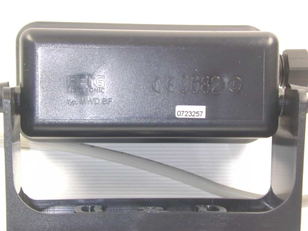
Click to zoom
Application Details
- Equipment Class
- FDS - Part 15 Field Disturbance Sensor
- Date of Grant
- Sep 17, 2002
- Application Purpose
- Original Equipment
- Date of Application
- Sep 17, 2002
- Equipment Note
- Radar Motion Detector
- Frequency Range
- 24120.00000000 - 24120.00000000
- Company
- Feig Electronic GmbH
- Country
- Germany
Documents & Files
Document Text
Text extracted from the exhibit documents filed with the FCC. Open a document above to read the original.
Users Manual
22.08.02 Instruction manual Digital Radar Motion Detector with Infrared Remote Control MWD BF FEIG ELECTRONIC GmbH Lange Straße 4 35781 Weilburg/Lahn MWD BFInstruction manual 208/02FEIG ELECTRONIC GmbH General Copyright2002byFEIG ELECTRONIC GmbH Lange Straße 4 D - 35781 Weilburg The indications made in these operating instructions may be altered without previous notice. With the edition of these instructions, all previous editions become void. Composition of the information given in this manual has been done to the best of our knowledge. FEIG ELECTRONIC does not guarantee the correctness of the details given in these instructions and may not be held liable for damages ensuing from incorrect installation. Since, despite of all our efforts, errors may not be completely avoided, we are always grateful for your useful tips. The installation instructions given in this manual are based on advantageous boundary conditions. FEIG ELECTRONIC does not give any guarantee promise for perfect function of the traffic detector in a cross surrounding. Copy or reproduction of these instructions, even if only partial, as well as translation into other languages is forbidden unless a written consent has been granted by FEIG ELECTRONIC. This also applies to the complete or partial storage of these operating instructions on modern input- and output media for further processing in data processing systems. Please read the operating- and safetyinstructionsthoroughly before putting the motion detector into operation!! BES_BF_eng.DOC, L-16657 Stand:22.08.02 Instruction manualMWD BF FEIG ELECTRONIC GmbH08/023 Contents FUNCTIONAL DESCRIPTION.....................................................................................................4 2INSTALLATION....................................................................................................................5 2.1Place of installation.........................................................................................................5 2.2Mounting of the bracket..................................................................................................5 2.3How to connect the motion detector.............................................................................5 2.4How to screw down the housing...................................................................................5 3ADJUSTMENT AND INITIATION.........................................................................................7 3.1Direction identification....................................................................................................7 3.2Device address................................................................................................................8 3.3LED display......................................................................................................................8 3.4Fall-delay time of relay....................................................................................................8 3.6Adjustment with key buttons..........................................................................................9 3.6.1Selection of sensitivity................................................................................................9 3.6.2Personal suppression.................................................................................................9 3.6.3Factory setting............................................................................................................9 3.7Adjustments with the infrared remote control MWD RC..............................................9 3.7.1How to activate the adjustment mode........................................................................9 3.7.2Selection of sensitivity..............................................................................................10 3.7.3Personal suppression...............................................................................................10 3.7.4How to terminate the adjustment mode....................................................................10 3.8Adjustment of the detection zone................................................................................10 3.9Initiation procedure.......................................................................................................11 3.10Possible reasons of malfunctions............................................................................11 5SAFETY INSTRUCTIONS..................................................................................................13 6TYPE APPROVAL..............................................................................................................14 7ABSTRACT.........................................................................................................................16 MWD BFInstruction manual 408/02FEIG ELECTRONIC GmbH Functional description The MWD BF is a radar motion detector with direction identification, which has been especially designed for applications in the area of industrial gate- and barrier systems. In some cases, the operational parameters may also be adjusted with an infrared remote control. Motion detection is done according to the Doppler’s principle. The sensor sends out 24 GHz microwaves. These microwaves are reflected by objects in motion and thus their frequency changes. The sensor receives these altered frequencies and analyses them. Thus, each motion within the detection range is recorded, analysed by a logic and transmitted to the gate- resp. barrier control by connecting potential-free change-over contacts. Range of application: Entry-/access recognition for the drive of industrial gate- and barrier systems Special features: •Insensitive to fluctuations of temperature and humidity •Distinction vehicles/persons •Reversible and cutoffdirection logic •Adjustablesensitivity •Potential-freerelay exit with change-over contacts •Largesupplyvoltage range - AC or DC •Adjustment ofoperational parameters…
Text truncated - open the document above for the full version.
Users Manual
14.05.03 Instruction manual Digital Radar Motion Detector with Infrared Remote Control MWD BF FEIG ELECTRONIC GmbH Lange Straße 4 35781 Weilburg/Lahn MWD BFInstruction manual 205/03FEIG ELECTRONIC GmbH General Copyright 2003 byFEIG ELECTRONIC GmbH Lange Straße 4 D - 35781 Weilburg The indications made in these operating instructions may be altered without previous notice. With the edition of these instructions, all previous editions become void. Composition of the information given in this manual has been done to the best of our knowledge. FEIG ELECTRONIC does not guarantee the correctness of the details given in these instructions and may not be held liable for damages ensuing from incorrect installation. Since, despite of all our efforts, errors may not be completely avoided, we are always grateful for your useful tips. The installation instructions given in this manual are based on advantageous boundary conditions. FEIG ELECTRONIC does not give any guarantee promise for perfect function of the traffic detector in a cross surrounding. Copy or reproduction of these instructions, even if only partial, as well as translation into other languages is forbidden unless a written consent has been granted by FEIG ELECTRONIC. This also applies to the complete or partial storage of these operating instructions on modern input- and output media for further processing in data processing systems. Please read the operating- and safety instructions thoroughly before putting the motion detector into operation!! BES_BF_eng.DOC, L-16657 Stand: 14.05.03 Instruction manualMWD BF FEIG ELECTRONIC GmbH05/033 Contents FUNCTIONAL DESCRIPTION .................................................................................................... 4 2INSTALLATION.................................................................................................................... 5 2.1 Place of installation......................................................................................................... 5 2.2 Mounting of the bracket.................................................................................................. 5 2.3 How to connect the motion detector ............................................................................. 5 2.4 How to screw down the housing ................................................................................... 5 3ADJUSTMENT AND INITIATION......................................................................................... 7 3.1 Direction identification ................................................................................................... 7 3.2 Device address ................................................................................................................ 8 3.3 LED display...................................................................................................................... 8 3.4 Fall-delay time of relay....................................................................................................8 3.6 Adjustment with key buttons ......................................................................................... 9 3.6.1 Selection of sensitivity ................................................................................................ 9 3.6.2 Personal suppression................................................................................................. 9 3.6.3 Factory setting............................................................................................................9 3.7 Adjustments with the infrared remote control MWD RC.............................................. 9 3.7.1 How to activate the adjustment mode ........................................................................ 9 3.7.2 Selection of sensitivity .............................................................................................. 10 3.7.3 Personal suppression............................................................................................... 10 3.7.4 How to terminate the adjustment mode.................................................................... 10 3.8 Adjustment of the detection zone................................................................................ 10 3.9 Initiation procedure....................................................................................................... 11 3.10 Possible reasons of malfunctions............................................................................ 11 5SAFETY INSTRUCTIONS.................................................................................................. 13 6TYPE APPROVAL.............................................................................................................. 14 7ABSTRACT ........................................................................................................................ 16 MWD BFInstruction manual 405/03FEIG ELECTRONIC GmbH Functional description The MWD BF is a radar motion detector with direction identification, which has been especially designed for applications in the area of industrial gate- and barrier systems. In some cases, the operational parameters may also be adjusted with an infrared remote control. Motion detection is done according to the Doppler’s principle. The sensor sends out 24 GHz microwaves. These microwaves are reflected by objects in motion and thus their frequency changes. The sensor receives these altered frequencies and analyses them. Thus, each motion within the detection range is recorded, analysed by a logic and transmitted to the gate- resp. barrier control by connecting potential-free change-over contacts. Range of application: Entry-/access recognition for the drive of industrial gate- and barrier systems Special features: • Insensitive to fluctuations of temperature and humidity • Distinction vehicles/persons • Reversible and cutoff direction logic • Adjustable sensitivity • Potential-free relay exit with change-over contacts • Large s…
Text truncated - open the document above for the full version.
Cover Letter(s)
Request for Confidentiality 05 September 2002 PHOENIX TEST-LAB GmbH Kˆnigswinkel 10 D32825 Blomberg Germany RE: Certification Application FCC ID: PJMMWDBF Please be advised that the following information is to be held confidential on behalf of FEIG ELECTRONIC GmbH: • Schematics • Block Diagram • Technical Description The application contains technical information which FEIG ELECTRONIC GmbH deems to be trade secrets and proprietary. If made public, the information might be used to the disadvantage of the applicant in the market place. Thank you for your attention to this matter.
External Photos
FCC ID: PJMMWDBF External Photos Page 1 of 8 FCC ID: PJMMWDBF External Photos Page 2 of 8 FCC ID: PJMMWDBF External Photos Page 3 of 8 FCC ID: PJMMWDBF External Photos Page 4 of 8 FCC ID: PJMMWDBF External Photos Page 5 of 8 FCC ID: PJMMWDBF External Photos Page 6 of 8 FCC ID: PJMMWDBF External Photos Page 7 of 8 FCC ID: PJMMWDBF External Photos Page 8 of 8
ID Label/Location Info
FCC-ID: PJMMWDBF This device complies with Part 15 of the FCC Rules, Operation is subject to the following two conditions: (1) this device may not cause harmful interference and (2) this device must accept any interference received, including interference that may cause undesired operation.
Internal Photos
FCC ID: PJMMWDBF Internal Photos Page 1 of 5 FCC ID: PJMMWDBF Internal Photos Page 2 of 5 FCC ID: PJMMWDBF Internal Photos Page 3 of 5 FCC ID: PJMMWDBF Internal Photos Page 4 of 5 FCC ID: PJMMWDBF Internal Photos Page 5 of 5
Test Report
EMV-Prüfzentrum EMI/EMC-Testcenter Page 1 of 23 Pages Straubing, September 17, 2002 T E S T - R E P O R T No. 50602-20351 for MWD BF Field Disturbance Sensor Applicant: FEIG ELECTRONIC GmbH Purpose of testing: To show compliance with FCC Code of Federal Regulations, Part 15 Subpart C, Section 15.245 Industry Canada Radio Standards Specification RSS-210 Issue 4, Section 6.1 (Category I Equipment) Note: The test data of this report relate only to the individual item which has been tested. This report shall not be reproduced except in full extent without the written approval of the testing laboratory. EMV-Prüfzentrum EMI/EMC-Testcenter Test Report No. 50602-20351 Page 2 of 23 Pages Table of Contents 1. Administrative Data.................................................................................... 3 2. Identification of Test Laboratory................................................................. 4 3. Summary of Test Results........................................................................... 5 4. Operation Mode of EUT ............................................................................. 6 5. Configuration of EUT and Peripheral Devices ........................................... 6 5.1 Description of peripheral devices connected to EUT........................... 6 5.2 Description of cables connected to EUT ............................................. 6 6. Measuring Methods ................................................................................... 7 6.1. Radiated Emission 30 MHz - 1 GHz (FCC §15.205.a,b, §15.209, §15.249 (a) / RSS-210 Sections 6.1.1.b, 6.3)....................... 7 6.2. Radiated Emission 1 GHz - 110 GHz (FCC §15.205.a,b, §15.209, §15.249 (a) / RSS-210 Sections 6.1.1.b, 6.3)....................... 8 7. Equipment List ........................................................................................... 9 8. Photographs Taken During Testing ......................................................... 11 9. List of Measurements............................................................................... 13 9.1. List of Measurements According To FCC Part 15 Subpart C .......................................................................................... 13 9.2. List of Measurements According To Industry Canada RSS-210 ............................................................................................ 13 10. Referenced Regulations .......................................................................... 14 11. Test Results ............................................................................................. 15 Charts taken during Testing ............................................................................. 17 EMV-Prüfzentrum EMI/EMC-Testcenter Test Report No. 50602-20351 Page 3 of 23 Pages 1. Administrative Data Test item (EUT) Type designation MWD BF Serial number(s): 0001 Type of equipment: Field Disturbance Sensor Parts/accessories: --- FCC-ID: Technical data Frequency range 24075 – 24175 MHz Operational frequency 24120 MHz Type of modulation 0H00N0N Pulse frequency N/A Pulse width N/A Antenna Integrated (rectangular horn) Power supply 12 – 24 DC or AC Applicant: (full address) FEIG ELECTRONIC GmbH Lange Strasse 4 35781 Weilburg-Waldhausen Contract identification: EB201736 / 16483 Contact person: Mr. Alwin Scheu Manufacturer: FEIG ELECTRONIC GmbH Application details Receipt of EUT: 28 May 2002 Date of test: June 2002 Note: Responsible for testing: Johann Roidt Responsible for test report: Johann Roidt EMV-Prüfzentrum EMI/EMC-Testcenter Test Report No. 50602-20351 Page 4 of 23 Pages 2. Identification of Test Laboratory Test Laboratory: (full address Senton GmbH EMI/EMC Test Center Aeussere Fruehlingstrasse 45 D-94315 Straubing / Germany Contact person Mr. Johann Roidt Communication: Telephone (+49) 0 94 21 / 55 22-0 Fax (+49) 0 94 21 / 55 22-99 eMail: [email protected] Laboratory accreditation: DATECH DAR-Registration No. TTI-P-G 062/94-40 FCC Test site registration File number 90926 Industry Canada File number IC 3050 EMV-Prüfzentrum EMI/EMC-Testcenter Test Report No. 50602-20351 Page 5 of 23 Pages 3. Summary of Test Results The tested sample complies with the requirements set forth in the Code of Federal Regulations CFR 47, Part 15 Subpart C, Section 15.245 Operation within the band 24075 to 24175 MHz and the Radio Standards Specification RSS-210 Issue 4, Section 6.2.2 (n) for Low Power Licence-Exempt Radiocommunication Devices (Field Disturbance Sensors). Johann Roidt Technical Manager EMV-Prüfzentrum EMI/EMC-Testcenter Test Report No. 50602-20351 Page 6 of 23 Pages 4. Operation Mode of EUT Continous operation, RX and TX on 5. Configuration of EUT and Peripheral Devices 5.1 Description of peripheral devices connected to EUT Item Designation Serial, part or ID no. Not applicable 5.2 Description of cables connected to EUT Item Cable length Serial, part or ID no. Unshielded power cable EMV-Prüfzentrum EMI/EMC-Testcenter Test Report No. 50602-20351 Page 7 of 23 Pages 6. Measuring Methods 6.1. Radiated Emission 30 MHz - 1 GHz (FCC §15.205.a,b, §15.209, §15.249 (a) / RSS-210 Sections 6.1.1.b, 6.3) Radiated emissions are measured over the frequency range from 30 MHz to 1 GHz. The bandwidth of the EMI-receiver is set to 120 kHz and the detector-function is set to CISPR quasi-peak. The test setup is made in accordance with ANSI C63.4-1992. Measurements are made in both the horizontal and vertical planes of polarization. Preliminary scans are taken in a fully-anechoic room using a spectrum analyzer with the detector function set to peak. Hand-held or body-worn devices are rotated through three orthogonal axes to determine which attitude and configuration produces the highest emission relative to the limit and therefore shall be used for final testing. All tests are performed at a test-distance of 3 meters. For final testing an open-area test-site is used. During the tests the EUT is rotated all around and the receiving-a…
Text truncated - open the document above for the full version.
Test Report
Conducted Emission Test 150 kHz - 30 MHz according to FCC Part 15 Subpart C Model: MWD BF Serial no.: --- Applicant: Feig Elektronik GmbH Test site: Shielded room, cabin no. 1 Tested on: Linecord 24 V AC Phase A Date of test: 11/25/2002 Operator: R. Heller Test performed: automatically File name: Detector: Peak / Final Results: QP Final results: Selected by hand Mode: - with supply voltage 24 V AC, 60 Hz TX + RX on 0.15 11030 MHz dBμV 100 90 80 70 60 50 40 30 20 10 0 Limit1: FCC C / QP Limit2: FCC C / AV Result: Limit kept Project file: 50602-20351 Page of Pages Senton GmbH / EMI/EMC Laboratories / Aeussere Fruehlingsstrasse 45 / D-94315 Straubing / Tel. +49 9421 55220 Conducted Emission Test 150 kHz - 30 MHz according to FCC Part 15 Subpart C Model: MWD BF Serial no.: --- Applicant: Feig Elektronik GmbH Test site: Shielded room, cabin no. 1 Tested on: Linecord 24 V AC Phase A Date of test: 11/25/2002 Operator: R. Heller Test performed: automatically File name: Detector: Peak / Final Results: QP Final results: Selected by hand Mode: - with supply voltage 24 V AC, 60 Hz TX + RX on Frequency MHz 0.155 0.207 0.260 0.315 0.365 0.520 0.575 0.730 0.885 1.146 1.300 1.354 1.565 Reading dBμV 50.7 42.9 45.6 45.0 42.2 40.7 37.2 38.5 37.8 38.9 38.2 39.5 37.4 Correction factor dB Value dBμV 50.7 42.9 45.6 45.0 42.2 40.7 37.2 38.5 37.8 38.9 38.2 39.5 37.4 Limit dBμV 65.7 63.3 61.4 59.8 58.6 56.0 56.0 56.0 56.0 56.0 56.0 56.0 56.0 Limit exceeded Result: Limit kept Project file: 50602-20351 Page of Pages Senton GmbH / EMI/EMC Laboratories / Aeussere Fruehlingsstrasse 45 / D-94315 Straubing / Tel. +49 9421 55220 Conducted Emission Test 150 kHz - 30 MHz according to FCC Part 15 Subpart C Model: MWD BF Serial no.: --- Applicant: Feig Elektronik GmbH Test site: Shielded room, cabin no. 1 Tested on: Linecord 24 V AC Phase A Date of test: 11/25/2002 Operator: R. Heller Test performed: automatically File name: Detector: Average / Final Results: AV Final results: Selected by hand Mode: - with supply voltage 24 V AC, 60 Hz TX + RX on 0.15 11030 MHz dBμV 100 90 80 70 60 50 40 30 20 10 0 Limit1: FCC C / QP Limit2: FCC C / AV Result: Limit kept Project file: 50602-20351 Page of Pages Senton GmbH / EMI/EMC Laboratories / Aeussere Fruehlingsstrasse 45 / D-94315 Straubing / Tel. +49 9421 55220 Conducted Emission Test 150 kHz - 30 MHz according to FCC Part 15 Subpart C Model: MWD BF Serial no.: --- Applicant: Feig Elektronik GmbH Test site: Shielded room, cabin no. 1 Tested on: Linecord 24 V AC Phase A Date of test: 11/25/2002 Operator: R. Heller Test performed: automatically File name: Detector: Average / Final Results: AV Final results: Selected by hand Mode: - with supply voltage 24 V AC, 60 Hz TX + RX on Frequency MHz 0.155 0.207 0.260 0.310 0.365 0.470 0.625 0.780 0.940 1.145 1.355 1.561 1.770 1.980 2.395 3.020 3.645 Reading dBμV 42.3 30.9 37.1 36.0 32.1 30.6 25.6 26.4 28.7 32.4 34.3 34.0 34.4 33.0 31.5 29.0 26.3 Correction factor dB Value dBμV 42.3 30.9 37.1 36.0 32.1 30.6 25.6 26.4 28.7 32.4 34.3 34.0 34.4 33.0 31.5 29.0 26.3 Limit dBμV 55.7 53.3 51.4 50.0 48.6 46.5 46.0 46.0 46.0 46.0 46.0 46.0 46.0 46.0 46.0 46.0 46.0 Limit exceeded Result: Limit kept Project file: 50602-20351 Page of Pages Senton GmbH / EMI/EMC Laboratories / Aeussere Fruehlingsstrasse 45 / D-94315 Straubing / Tel. +49 9421 55220 Conducted Emission Test 150 kHz - 30 MHz according to FCC Part 15 Subpart C Model: MWD BF Serial no.: --- Applicant: Feig Elektronik GmbH Test site: Shielded room, cabin no. 1 Tested on: Linecord 24 V AC Phase B Date of test: 11/25/2002 Operator: R. Heller Test performed: automatically File name: Detector: Peak / Final Results: QP Final results: Selected by hand Mode: - with supply voltage 24 V AC, 60 Hz TX + RX on 0.15 11030 MHz dBμV 100 90 80 70 60 50 40 30 20 10 0 Limit1: FCC C / QP Limit2: FCC C / AV Result: Limit kept Project file: 50602-20351 Page of Pages Senton GmbH / EMI/EMC Laboratories / Aeussere Fruehlingsstrasse 45 / D-94315 Straubing / Tel. +49 9421 55220 Conducted Emission Test 150 kHz - 30 MHz according to FCC Part 15 Subpart C Model: MWD BF Serial no.: --- Applicant: Feig Elektronik GmbH Test site: Shielded room, cabin no. 1 Tested on: Linecord 24 V AC Phase B Date of test: 11/25/2002 Operator: R. Heller Test performed: automatically File name: Detector: Peak / Final Results: QP Final results: Selected by hand Mode: - with supply voltage 24 V AC, 60 Hz TX + RX on Frequency MHz 0.155 0.208 0.260 0.310 0.365 0.470 0.519 0.675 0.935 1.145 1.355 1.510 1.560 Reading dBμV 50.8 42.5 45.6 45.3 42.4 40.1 40.9 37.2 37.8 38.5 38.5 36.7 37.2 Correction factor dB Value dBμV 50.8 42.5 45.6 45.3 42.4 40.1 40.9 37.2 37.8 38.5 38.5 36.7 37.2 Limit dBμV 65.7 63.3 61.4 60.0 58.6 56.5 56.0 56.0 56.0 56.0 56.0 56.0 56.0 Limit exceeded Result: Limit kept Project file: 50602-20351 Page of Pages Senton GmbH / EMI/EMC Laboratories / Aeussere Fruehlingsstrasse 45 / D-94315 Straubing / Tel. +49 9421 55220 Conducted Emission Test 150 kHz - 30 MHz according to FCC Part 15 Subpart C Model: MWD BF Serial no.: --- Applicant: Feig Elektronik GmbH Test site: Shielded room, cabin no. 1 Tested on: Linecord 24 V AC Phase B Date of test: 11/25/2002 Operator: R. Heller Test performed: automatically File name: Detector: Average / Final Results: AV Final results: Selected by hand Mode: - with supply voltage 24 V AC, 60 Hz TX + RX on 0.15 11030 MHz dBμV 100 90 80 70 60 50 40 30 20 10 0 Limit1: FCC C / QP Limit2: FCC C / AV Result: Limit kept Project file: 50602-20351 Page of Pages Senton GmbH / EMI/EMC Laboratories / Aeussere Fruehlingsstrasse 45 / D-94315 Straubing / Tel. +49 9421 55220 Conducted Emission Test 150 kHz - 30 MHz according to FCC Part 15 Subpart C Model: MWD BF Serial no.: --- Applicant: Feig Elektronik GmbH Test site: Shielded room, cabin no. 1 Tested on: Linecord 24 V AC Phase B Date of test: 11/25/2002 Operator: R. Heller Test performed: automatically File name: Detector: Average / Final Results: AV Final results: Selected …
Text truncated - open the document above for the full version.
Test Setup Photos
EMV-Pr ̧fzentrum EMI/EMC-Testcenter Test Report No. 50602-20351 Page 11 of 23 Pages 8. Photographs Taken During Testing Test setup for radiated emission pre-test 30 MHz - 1 GHz (fully anechoic room) EMV-Pr ̧fzentrum EMI/EMC-Testcenter Test Report No. 50602-20351 Page 12 of 23 Pages Test setup for radiated emission test above 18 GHz
Contact Information
Applicant
Elmar Reichwein(Manager)
Technical Contact
Senton GmbHJohann Roidt
[email protected]+49-9421-55 22 13
Aeussere Fruehlingstrasse 45 · Straubing · Germany
Non-Technical Contact
Senton GmbHJohann Roidt
[email protected]+49-9421-55 22 13
Test Firm
TUV SUD Product Service GmbH PS-EMC-STRRainer Heller
Technical Specifications
| # | Rule Parts | Frequency Range | Power Output |
|---|---|---|---|
| 1 | 15.245 | 24.12 GHz - 24.12 GHz | - |
Other Applications from Feig Electronic GmbH

PJMPRM103
Feb 25, 2026RFID Reader
Equipment Class
DXX - Part 15 Low Power Communication Device Transmitter
PJMMRM103
Jan 19, 2026RFID Reader
Equipment Class
DXX - Part 15 Low Power Communication Device TransmitterPJMTSTFSAMC
Dec 01, 2024Wireless Safety System for industrial doors - Mobile Unit
Equipment Class
DXX - Part 15 Low Power Communication Device Transmitter
PJMLRM5400
Jun 27, 2023RFID Reader
Equipment Class
DXX - Part 15 Low Power Communication Device Transmitter
PJMMRU102A
Jul 07, 2021RFID Reader
Equipment Class
DSS - Part 15 Spread Spectrum Transmitter