PJMMWDBPMotion Detector
Feig Electronic GmbH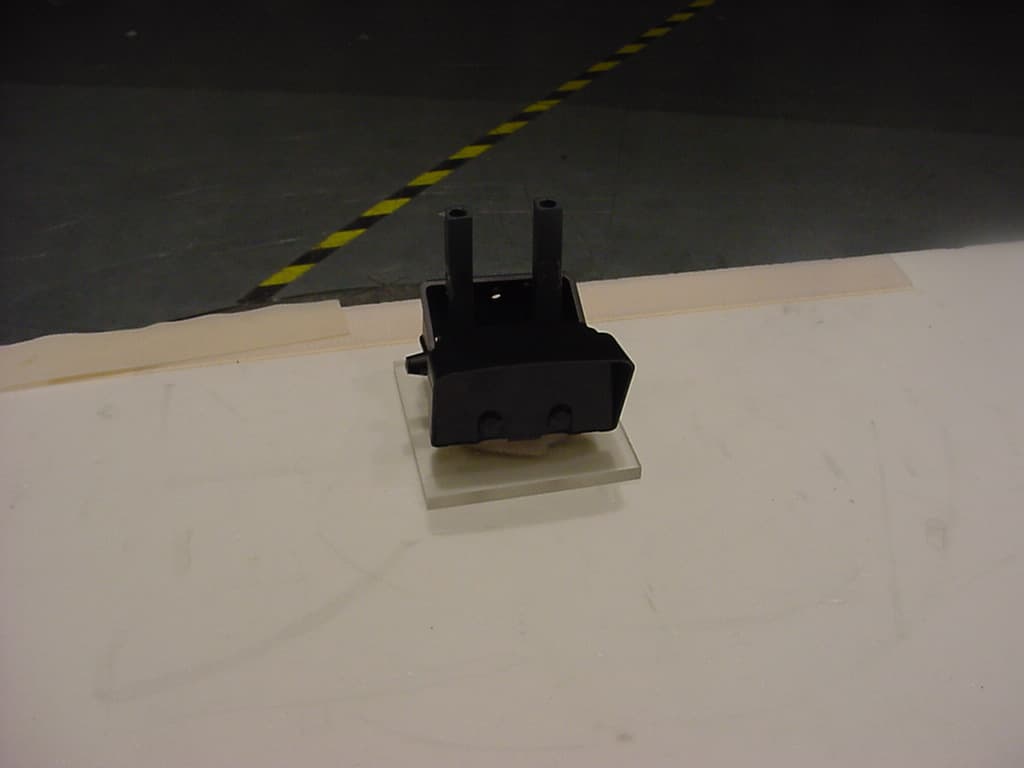
Click to zoom
Application Details
- Equipment Class
- FDS - Part 15 Field Disturbance Sensor
- Date of Grant
- Aug 22, 2006
- Application Purpose
- Original Equipment
- Date of Application
- Aug 22, 2006
- Equipment Note
- Motion Detector
- Frequency Range
- 24075.00000000 - 24175.00000000
- Company
- Feig Electronic GmbH
- Country
- Germany
Documents & Files
Document Text
Text extracted from the exhibit documents filed with the FCC. Open a document above to read the original.
Users Manual
Instruction Manual 07/21/2006 Manual MWD BP.doc Radar Motion Detector – MWD BP Instruction ManualRadar Motion Detector MWD BP2/13 Manual MWD BP.docas 07/21/2006FEIG ELECTRONIC GmbH General © Copyright 2006 byFEIG ELECTRONIC GmbH Lange Straße 4 35781 Weilburg Germany The indications made in these operating instructions may be altered without previous notice. With the edition of these instructions, all previous editions become void. Composition of the information given in this manual has been done to the best of our knowledge. FEIG ELEC- TRONIC does not guarantee the correctness of the details given in these instructions and may not be held liable for damages ensuing from incorrect installation. Since, despite of all our efforts, errors may not be completely avoided, we are always grateful for your useful tips. The installation instructions given in this manual are based on advantageous boundary conditions. FEIG ELEC- TRONIC does not give any guarantee promise for perfect function of the traffic detector in a cross surrounding. Copy or reproduction of these instructions, even if only partial, as well as translation into other languages is for- bidden unless a written consent has been granted by FEIG ELECTRONIC. This also applies to the complete or partial storage of these operating instructions on modern input- and output media for further processing in data processing systems. Please read the operating- and safety instructions thoroughly before putting the motion detector into opera- tion ! Instruction ManualRadar Motion Detector MWD BP3/13 Manual MWD BP.docas 07/21/2006FEIG ELECTRONIC GmbH Contents 1 Functional description____________________________________4 2 Installation _____________________________________________5 2.1Place of installation _________________________________________________________ 5 2.2Hints for planning and installation:____________________________________________ 5 3 Parameter Entry _________________________________________6 3.1Open Parameter Entry ______________________________________________________ 6 3.2Change Parameter__________________________________________________________ 6 3.3Close Parameter Entry ______________________________________________________ 7 3.4Show Service Parameter _____________________________________________________ 7 4 Standard Parameter List __________________________________8 5 Service Parameter List____________________________________9 6 Profiles ________________________________________________9 7 Notes _________________________________________________10 8 Connections___________________________________________10 9 Technical data _________________________________________10 10 Type Approval _________________________________________11 10.1 Europe (CE) ______________________________________________________________ 11 10.2 USA (FCC) / Canada (IC)___________________________________________________ 12 11 Safety instructions ______________________________________13 Instruction ManualRadar Motion Detector MWD BP4/13 Manual MWD BP.docas 07/21/2006FEIG ELECTRONIC GmbH 1 Functional description The MWD BP is a radar motion detector with direction identification, which has been especially designed for applications in the area of industrial gate- and barrier systems. In some cases, the operational parameters may also be adjusted with an infrared remote control. Motion detection is done according to the Doppler’s principle. The sensor sends out 24 GHz microwaves. These microwaves are reflected by objects in motion and thus their frequency changes. The sensor receives these altered frequencies and analyses them. Thus, each motion within the detection range is recorded, analyzed by a logic and transmitted to the gate- resp. barrier control by connecting potential-free change-over contacts. Range of application: Entry-/access recognition for the drive of industrial gate- and barrier systems Special features: • Insensitive to fluctuations of temperature and humidity • Distinction vehicles/persons • Suppression of cross traffic • Object tracking for slow objects • Reversible and cutoff direction logic • Adjustable sensitivity • Application specific parameter profiles • Two channel with individual parameter setting • Two potential-free relay contacts • Large supply voltage range - AC or DC • Adjustment of operational parameters by key buttons or infrared remote control and 7-segment display • Compact plastic housing • IP 65 housing • Easy and fast installation with mounting bracket Instruction ManualRadar Motion Detector MWD BP5/13 Manual MWD BP.docas 07/21/2006FEIG ELECTRONIC GmbH 2 Installation 2.1 Place of installation The device is centrally mounted above the area to be monitored. Both wall- and ceiling mounting are possible. The maximum mounting height is 7m. 2.2 Hints for planning and installation: • The device has to be mounted vibrationless. • In order to avoid incorrect release, there must not be any objects in motion within the radiation field. • There must not be any fluorescent tubes within the radiation field of the detector. • It should be avoided that the radiation fields of two motion detectors overlap, since this may lead to incorrect releases. • Do not install behind objects, building coverings or elements. • If the motion detector is exposed to rain or snow, it should be adjusted to directional recognition. • If conductive floors are used and the radiation direction is almost vertical, incorrect releases may be caused by reflections. Instruction ManualRadar Motion Detector MWD BP6/13 Manual MWD BP.docas 07/21/2006FEIG ELECTRONIC GmbH 3 Parameter Entry 3.1 Open Parameter Entry a) Remote Control MWD RC SymbolKey Key- press DescriptionAction Display Example 1. i i -Button short Channel 1: displayed address Channel 2: displayed address + 1 Actual device address is displayed with blinking digit and decimal point Ñ1.Ò 2a. 1..4 value 1..4short Direct confirmation of device address Display first parameter name L. or Volume + 2. 2b. Volume - short…
Text truncated - open the document above for the full version.
External Photos
CETECOM ICT Services GmbH Test report No.: 2-3820-01-05/04 Date: 2006-06-27Page 25 of 29 Photo no. 2
ID Label/Location Info
MWD BP Alwin Scheu 08/14/2006 Label MWD BP_06_08_14.doc - Label - 24 GHz Motion Detector MWD BP with IR-Receiver bottom side view: Typ: MWD BP FCC ID: PJMMWDBP IC: 6633A-MWDBP Outline removable die plate Logo: Height5.5mm FCC-ID / IC: Frame9x31mm FontArial Font Size 8 WEEE-Sign: CE-Sign: with notified body no. and Class II identifier (alert sign) Model No: FontArial Font Size 8 Label
Internal Photos
CETECOM ICT Services GmbH Test report No.: 2-3820-01-05/04 Date: 2006-06-27Page 26 of 29 Pictures of the sample Photo no. 3 CETECOM ICT Services GmbH Test report No.: 2-3820-01-05/04 Date: 2006-06-27Page 27 of 29 Photo no. 4 CETECOM ICT Services GmbH Test report No.: 2-3820-01-05/04 Date: 2006-06-27Page 28 of 29 Photo no. 5
Test Report
CETECOM ICT Services GmbH Radio Satellite Communication Untertürkheimer Straße 6–10, D-66117 Saarbrücken, Telephone +49 (0) 681 598 - 0, Fax +49 (0) 681 598 - 9075 Test report No.: 2-3820-01-05/04 This test report consists of 29 pages Page 1 of 29 Recognized by the Federal Communications Commission and Industry Canada Anechoic chamber registration No.: 90462 (FCC) Anechoic chamber registration No.: 3463 (IC) TCB ID: DE0001 Accredited by the German Accreditation Council DAR–Registration Number DAT-P-176/94-D1 Independent ETSI compliance test house ETSI Test report No. 2-3820-01-05/04 Feig Electronic GmbH MWD BP FCC ID: PJMMWDBP IC: 6633A-MWDBP Test standard: FCC Part 15 / RSS-210 CETECOM ICT Services GmbH Test report No.: 2-3820-01-05/04 Date: 2006-06-27Page 2 of 29 Table of contents Page 1 General information..........................................................................................................................................................3 1.1 Notes ..........................................................................................................................................................................3 1.2 Testing laboratory.......................................................................................................................................................4 1.3 Details of applicant.....................................................................................................................................................4 1.4 Application details......................................................................................................................................................4 1.5 Test item (EUT)..........................................................................................................................................................5 1.6 Operation conditions ..................................................................................................................................................6 1.7 Test standards .............................................................................................................................................................6 2 Technical test ....................................................................................................................................................................7 2.1 Summary of test results ..............................................................................................................................................7 2.2 Test environment ........................................................................................................................................................7 2.3 Measurement and test set-up ......................................................................................................................................7 2.4 Test equipment utilized and test set-up ......................................................................................................................8 2.4.1 Field strength measurement of fundamental and spurious in the frequency range 0.9 GHz to 33 GHz ...........8 2.4.2 Field strength and spurious radiation in the frequency range 33 GHz to 110 GHz ..........................................9 2.4.3 Field strength and spurious radiation in the frequency range 9 kHz to 12 GHz .............................................10 2.5 Test results................................................................................................................................................................11 2.5.1 Test results overview ......................................................................................................................................11 2.5.2 Remarks on methods of measurements...........................................................................................................11 2.5.3 Test results in details.......................................................................................................................................12 3 Measurement results .......................................................................................................................................................14 4 Photographs ....................................................................................................................................................................24 CETECOM ICT Services GmbH Test report No.: 2-3820-01-05/04 Date: 2006-06-27Page 3 of 29 1 General information 1.1 Notes The test results of this test report relate exclusively to the test item specified in 1.5. CETECOM ICT Services GmbH does not assume responsibility for any conclusions and generalizations drawn from the test results with regard to other specimens or samples of the type of the equipment represented by the test item. The test report may only be reproduced or published in full. Reproduction or publication of extracts from the report requires the prior written approval of the CETECOM ICT Services GmbH. Tester: Date Name Signature 2006-06-27 Harro Ames Technical responsibility for area of testing: Date Name Signature 2006-006-27 Dirk Hausknecht CETECOM ICT Services GmbH Test report No.: 2-3820-01-05/04 Date: 2006-06-27Page 4 of 29 1.2 Testing laboratory CETECOM ICT Services GmbH CETECOM ICT Services GmbH Untertürkheimerstraße 6–10 P.O. Box 10 04 45 D-66117 Saarbrücken D-66004 Saarbrücken Germany Germany Telephone : + 49 (0) 681 598–0 Fax : + 49 (0) 681 598–9075 e-mail : [email protected] Internet : http://www.cetecom-ict.de Accredited testing laboratory Accredited by : Regulierungsbehörde für Telekommunikation und Post (RegTP) Listed by : Federal Communications Commission (FCC) Industry Canada (IC) Authority Identification/Registration No. RegTP DAT-P-176/94-D1 FCC 90462 IC 3463 Testing location, if different from CETECOM ICT Services GmbH: (not applicable) 1.3 Details of applicant Name : Feig El…
Text truncated - open the document above for the full version.
Test Setup Photos
CETECOM ICT Services GmbH Test report No.: 2-3820-01-05/04 Date: 2006-06-27Page 24 of 29 4 Photographs Photo no. 1 radiated emissions CETECOM ICT Services GmbH Test report No.: 2-3820-01-05/04 Date: 2006-06-27Page 25 of 29 Photo no. 2 CETECOM ICT Services GmbH Test report No.: 2-3820-01-05/04 Date: 2006-06-27Page 29 of 29 Photo no. 6 AC conducted
Contact Information
Applicant
Elmar Reichwein(Manager)
Test Firm
cetecom advanced GmbHGerald Schmidt
Technical Specifications
| # | Rule Parts | Frequency Range | Power Output |
|---|---|---|---|
| 1 | 15.245 | 24.07 GHz - 24.18 GHz | - |
Other Applications from Feig Electronic GmbH

PJMPRM103
Feb 25, 2026RFID Reader
Equipment Class
DXX - Part 15 Low Power Communication Device Transmitter
PJMMRM103
Jan 19, 2026RFID Reader
Equipment Class
DXX - Part 15 Low Power Communication Device TransmitterPJMTSTFSAMC
Dec 01, 2024Wireless Safety System for industrial doors - Mobile Unit
Equipment Class
DXX - Part 15 Low Power Communication Device Transmitter
PJMLRM5400
Jun 27, 2023RFID Reader
Equipment Class
DXX - Part 15 Low Power Communication Device Transmitter
PJMMRU102A
Jul 07, 2021RFID Reader
Equipment Class
DSS - Part 15 Spread Spectrum Transmitter