PJMPRH100Inductive Tag Reader
Feig Electronic GmbH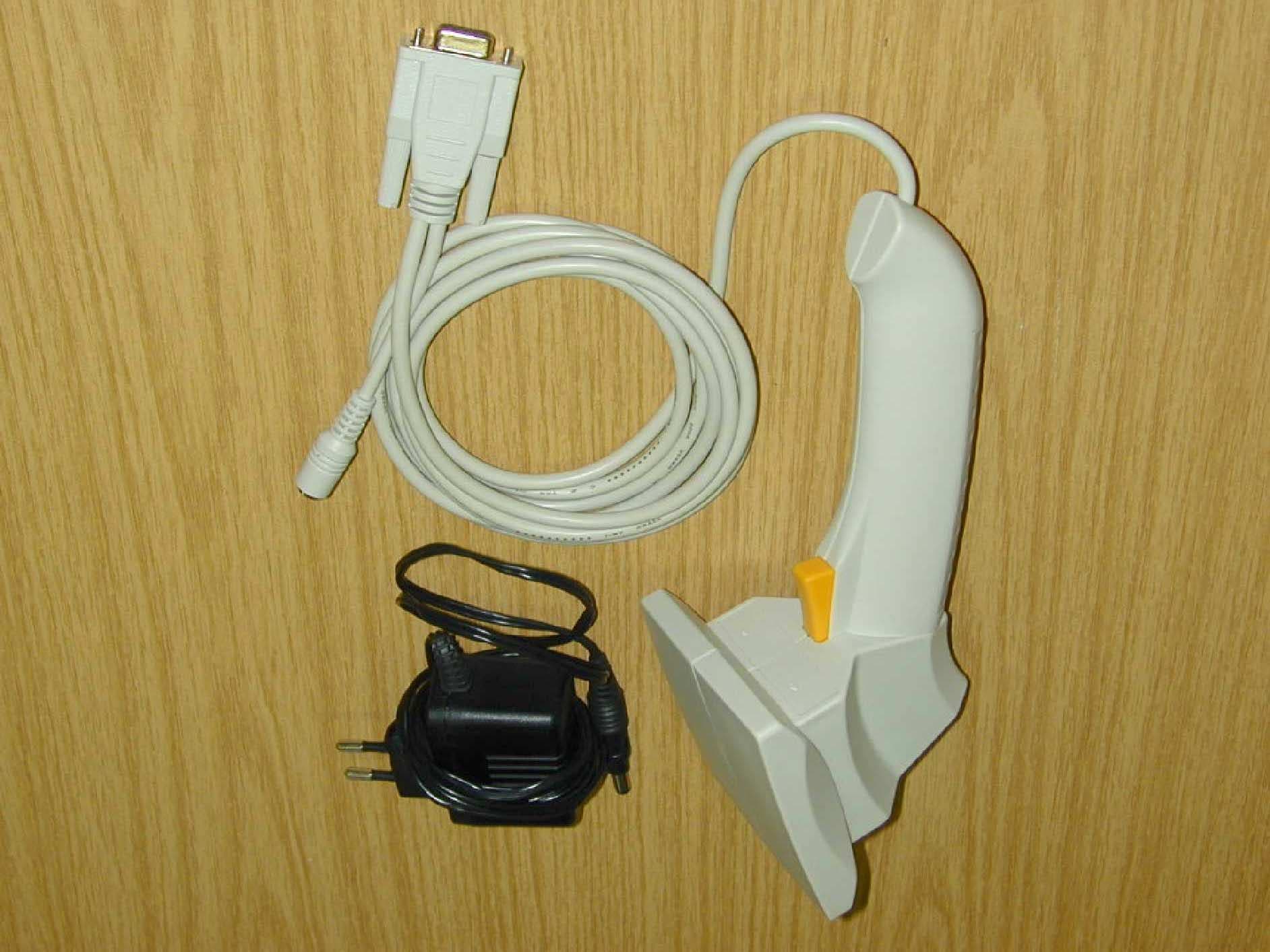
Click to zoom
Application Details
- Equipment Class
- DXX - Part 15 Low Power Communication Device Transmitter
- Date of Grant
- Sep 28, 2001
- Application Purpose
- Original Equipment
- Date of Application
- Sep 28, 2001
- Equipment Note
- Inductive Tag Reader
- Frequency Range
- 13.56000000 - 13.56000000
- Company
- Feig Electronic GmbH
- Country
- Germany
Documents & Files
Document Text
Text extracted from the exhibit documents filed with the FCC. Open a document above to read the original.
Users Manual
M10501-1e-ID-B.DOC OBID i-scan Mounting Instruction ID ISC.PRH100-A (english) MountingInstruction ID ISC.PRH100-A FEIG ELECTRONIC GmbH Type approval Europe (CE) When used according to regulation, this radio equipment conforms with the basic requirements of Article 3 and the other relevant provisions of the R&TTE Guideline 1999/E6 dated March 99. USA (FCC) FCC ID: PJMPRH100 This device complies with Part 15 of the FCC Rules. Operation is subject to the following two conditions: (1) this device may not cause harmful interference, and (2) this device must accept any interference received, including interference that may cause undesired operation. Unauthorized modifications may void the authority granted under Federal communications Commission Rules permitting the operation of this device.
Cover Letter(s)
Request for Confidentiality FCC ID No:PJMPRH100 Applicant:Feig Electronic GmbH Filed:September 25, 2001 Feig Electronic requests, pursuant to 47CFR 0.459, post grant confidentiality for portions of the material contained in this application such that the identified material will be withheld from public inspection following the grant of this authorization. Thi s material, as indicated by request for confidentiality of the item during the electronic submission process and further identified below, includes: 1. Electrical Schematics, Adobe Acrobat file ́PRH100-Schematics.pdf ́ (7 pages) 2. Layout, Adobe Acrobat file ́PRH100-Layout ́ (6 pages) 3. Block Diagram, Adobe Acrobat file ́PRH100-Blockdiagram.pdf ́ (1 page) Specifically, these exhibits contain information relating to the circuit function and complexity that could be benefit to competitors. The material contains trade secrets and confidential information that Feig Electronic does not customarily release to the public and which is otherwise not generally available to the public. Please contact me by phone at +49 6471-3109-95, by fax at +49 6471-3109-99, by email at [email protected], or by correspondence at the address below if there is any further question or additional information needed concerning this filing. Regards, Carsten Fiedler Feig Electronic GmbH Lange Str. 4 35781 Weilburg Germany
Cover Letter(s)
EMV-Pr ̧fzentrum EMI/EMC-Testcenter Hausanschrift:Sparkasse (BLZ 742 500 00) 14 076Handelsregister Straubing ƒussere Fr ̧hlingstrasse 45 ! D-94315 StraubingDeutsche Bank (BLZ 750 700 13) 9 855 255HRB-Nr. 9302 Telefon (0 94 21) 55 22-0Dresdner Bank (BLZ 700 800 00) 0 803 965 300Gesch‰ftsf ̧hrer: Telefax (0 94 21) 55 22-99HypoVereinsbank (BLZ 742 200 75) 2 615 649Johann Roidt, Manfred Amann [email protected] ! http://www.senton.dePostgiro N ̧rnberg (BLZ 760 100 85) 1 778 87 857 Senton GmbH ! ƒussere Fr ̧hlingstrasse 45 ! D-94315 Straubing David A.Case American TCB 09/27/2001 In reference to FCC ID PJMPRH100 Mr. Case 1. A corrected version of the report will be uploaded through American TCB website. 2. The prescans were made in a semianechoic chamber with the detector of the spectrum analyser set to peak. Final measurement at an Open Area Test Site with the CISPR quasi peak detector resulted in marginal pass. The difference in readings from pretest and final measurement is caused by the pulsed emission of the EUT. Johann Roidt Senton GmbH
External Photos
FCC ID: PJMPRH100External Photographs Page 1 of 2 FCC ID PJMPRH100 / Feig Electronic GmbH External Photographs FCC ID: PJMPRH100External Photographs Page 2 of 2
ID Label/Location Info
FCC ID: PJMPRH100Label Information Page 1 of 1 FCC ID PJMPRH100 / Feig Electronic GmbH Label Information
ID Label/Location Info
IDISC.PRH100-A 5V 0682 FCCID:PJMPRH100 MadeinGermany IDISC.PRH100-A 5V 0682 FCCID:PJMPRH100 MadeinGermany M1:1 M4:1
Internal Photos
FCC ID: PJMPRH100Internal Photographs Page 1 of 3 FCC ID PJMPRH100 / Feig Electronic GmbH Internal Photographs FCC ID: PJMPRH100Internal Photographs Page 2 of 3 FCC ID: PJMPRH100Internal Photographs Page 3 of 3
Test Report
FCC-ID: Test Report No. 50602-10395-2 Page 1 of 25 Pages Straubing, August 27, 2001 T E S T - R E P O R T No. 50602-10395-2 for ID ISC.PRH100 Inductive Tag Reader Applicant:FEIG ELECTRONIC GmbH Purpose of testing:To show compliance with FCC Code of Federal Regulations, CFR 47, Part 15, Subpart C, Section 15.225 Note: The test data of this report relate only to the individual item which has been tested. This report shall not be reproduced except in full extent without the written approval of the testing laboratory. FCC-ID: Test Report No. 50602-10395-2 Page 2 of 25 Pages Table of Contents 1. Administrative Data ............................................................................................. 3 2. Identification of Test Laboratory.......................................................................... 4 3. Summary of Test Results .................................................................................... 5 4. Operation Mode of EUT ...................................................................................... 6 5. Configuration of EUT and Peripheral Devices..................................................... 7 6. Measuring Methods............................................................................................. 8 6.1. Field strength of in-band emissions (§15.225 (a)) and unwantewd emissions < 30 MHz (§15.225 (b)) ............................................ 8 6.2. Frequency tolerance (§15.225 (c)) ............................................................... 9 6.3. Unwanted Emission 30 MHz - 1 GHz (§15.225 (b)).................................... 11 7. Photographs of Test Setups.............................................................................. 13 7.1. Radiated Emissions 9 kHz – 30 MHz............................................................. 13 7.2. Radiated Emissions 30 – 1000 MHz .............................................................. 14 8. Equipment List .................................................................................................. 15 9. Referenced Regulations.................................................................................... 17 10. List of Measurements ........................................................................................ 18 11. Test Results ...................................................................................................... 19 12. Chartsd taken during testing ............................................................................. 25 FCC-ID: Test Report No. 50602-10395-2 Page 3 of 25 Pages 1.Administrative Data Equipment Under Test (EUT):ID ISC.PRH100 Serial number(s):Sample no. 1 Type of equipment:Inductive Tag Reader Type of emission:14K0A1D Parts/accessories:--- FCC-ID: PJM Applicant:FEIG ELECTRONIC GmbH (full address)Lange Strasse 4 D-35781 Weilburg-Waldhausen Contract identification:--- Contact person:Mr. Carsten Fiedler Manufacturer:FEIG ELECTRONIC GmbH Receipt of EUT:June 20, 2001 Dates of test:June 22, 2001 Note:--- Responsible for testing:Johann Roidt Responsible for test report:Johann Roidt FCC-ID: Test Report No. 50602-10395-2 Page 4 of 25 Pages 2.Identification of Test Laboratory Test Laboratory:Senton GmbH EMI/EMC Test Center (full address):Aeussere Fruehlingstrasse 45 D-94315 Straubing Germany Contact person:Mr. Johann Roidt Communication:Telephone(+49) 0 94 21 / 55 22-0 Fax (+49) 0 94 21 / 55 22-99 eMail:[email protected] FCC registration number:90926 Industry Canada file number:IC 3050 FCC-ID: Test Report No. 50602-10395-2 Page 5 of 25 Pages 3.Summary of Test Results The tested sample complies with the requirements for set forth in the The Code of Federal Regulations 47, Part 15, Subpart C, Section 15.225 of the Federal Communication Commission (FCC). Johann Roidt Technical Manager FCC-ID: Test Report No. 50602-10395-2 Page 6 of 25 Pages 4.Operation Mode of EUT Continously reading a TAG FCC-ID: Test Report No. 50602-10395-2 Page 7 of 25 Pages 5.Configuration of EUT and Peripheral Devices Configuration of cables of EUT Not applicable Configuration of peripheral devices connected to EUT All tests were performed with the EUT connected to a personal computer via either the RS 232 interface or USB bus. The RS232 version of the EUIT was powered by an external AC adapter. THE USB version received power via the USB bus. FCC-ID: Test Report No. 50602-10395-2 Page 8 of 25 Pages 6.Measuring Methods 6.1. Field strength of in-band emissions (§15.225 (a)) and unwanted emissions < 30 MHz (§15.225 (b)) Radiated emissions in the frequency range 9 kHz – 30 MHz will be measured initially at a distance of 3 meters. A prescan at 3 meter distance will be performed in a shielded room with the detector of the spectrum analyzer or EMI Receiver set to peak. Final measurement is then performed at 30 meter distance. In case the regulation requires testing at other distances, the result will be extrapolated. The extrapolation factor will be determined by making a second measurement at 10 meter distance. The provisions of 15.31 (d) apply. According to section 15.209 (d) final measurementis performed with the detector set to Quasi Peak except for the frequency bands 9 – 90 kHz and 110 – 490 kHz where average detector is employed. FCC-ID: Test Report No. 50602-10395-2 Page 9 of 25 Pages 6.2. Frequency tolerance (§15.225 (c)) 6.2.1. Frequency stability vs. temperature The frequency stability vs. temperature was measured with a spectrum analyzer connected to the output of the transmitter power amplifier (conducted measurement) via dummy load while EUT was operating in transmit mode using the assigned frequency. The trace mode of the spectrum analyzer was set to write with frequency count mode activated: RBW = 100 Hz, VBW = 100 Hz, span = 20 kHz, sweep = 1.5 s (auto mode) See figure 1 for the measurement setup. Test equipment used (see equipment list for details): 02, 18, 51, 54, 69, 70, 71 6 9 4 7 5 8 1 2 3 Figure 1: Measurement setup for testing within temperat…
Text truncated - open the document above for the full version.
Test Report
FCC-ID: PJMPRH100Test Report No. 50602-10395-2 Page 1 of 49 Pages Straubing, September 18, 2001 T E S T - R E P O R T No. 50602-10395-2 for ID ISC.PRH100 Inductive Tag Reader Applicant:FEIG ELECTRONIC GmbH Purpose of testing:To show compliance with FCC Code of Federal Regulations, CFR 47, Part 15, Subpart C, Section 15.225 Note: The test data of this report relate only to the individual item which has been tested. This report shall not be reproduced except in full extent without the written approval of the testing laboratory. FCC-ID: PJMPRH100Test Report No. 50602-10395-2 Page 2 of 49 Pages Table of Contents 1. Administrative Data ..............................................................................................3 2. Identification of Test Laboratory ...........................................................................4 3. Summary of Test Results.....................................................................................5 4. Operation Mode of EUT .......................................................................................6 5. Configuration of EUT and Peripheral Devices ......................................................7 6. Measuring Methods..............................................................................................8 6.1. Field strength of in-band emissions (ß15.225 (a)) and unwantewd emissions < 30 MHz (ß15.225 (b))..............................................8 6.2. Frequency tolerance (ß15.225 (c)) ................................................................9 6.3. Unwanted Emission 30 MHz - 1 GHz (ß15.225 (b)) .....................................11 7. Photographs of Test Setups...............................................................................13 7.1. Radiated Emissions 9 kHz ñ 30 MHz ..............................................................13 7.2. Radiated Emissions 30 ñ 1000 MHz ...............................................................14 8. Equipment List ...................................................................................................15 9. Referenced Regulations.....................................................................................17 10. List of Measurements.........................................................................................18 11. Test Results .......................................................................................................19 12. Chartsd taken during testing ..............................................................................25 FCC-ID: PJMPRH100Test Report No. 50602-10395-2 Page 3 of 49 Pages 1.Administrative Data Equipment Under Test (EUT):ID ISC.PRH100 Serial number(s):Sample no. 1 Type of equipment:Inductive Tag Reader Type of emission:10K0A1D Parts/accessories:--- FCC-ID:PJMPRH100 Applicant:FEIG ELECTRONIC GmbH (full address)Lange Strasse 4 D-35781 Weilburg-Waldhausen Contract identification:--- Contact person:Mr. Carsten Fiedler Manufacturer:FEIG ELECTRONIC GmbH Receipt of EUT:June 20, 2001 Dates of test:June 22, 2001 Note:--- Responsible for testing:Johann Roidt Responsible for test report:Johann Roidt FCC-ID: PJMPRH100Test Report No. 50602-10395-2 Page 4 of 49 Pages 2.Identification of Test Laboratory Test Laboratory:Senton GmbH EMI/EMC Test Center (full address):Aeussere Fruehlingstrasse 45 D-94315 Straubing Germany Contact person:Mr. Johann Roidt Communication:Telephone(+49) 0 94 21 / 55 22-0 Fax (+49) 0 94 21 / 55 22-99 eMail:[email protected] FCC registration number:90926 Industry Canada file number:IC 3050 FCC-ID: PJMPRH100Test Report No. 50602-10395-2 Page 5 of 49 Pages 3.Summary of Test Results The tested sample complies with the requirements for set forth in the The Code of Federal Regulations 47, Part 15, Subpart C, Section 15.225 of the Federal Communication Commission (FCC). Johann Roidt Technical Manager FCC-ID: PJMPRH100Test Report No. 50602-10395-2 Page 6 of 49 Pages 4.Operation Mode of EUT Continously reading a TAG FCC-ID: PJMPRH100Test Report No. 50602-10395-2 Page 7 of 49 Pages 5.Configuration of EUT and Peripheral Devices Configuration of cables of EUT Not applicable Configuration of peripheral devices connected to EUT All tests were performed with the EUT connected to a personal computer via either the RS 232 interface or USB bus. The RS232 version of the EUT was powered by an external AC adapter. THE USB version received power via the USB bus. FCC-ID: PJMPRH100Test Report No. 50602-10395-2 Page 8 of 49 Pages 6.Measuring Methods 6.1. Field strength of in-band emissions (ß15.225 (a)) and unwanted emissions < 30 MHz (ß15.225 (b)) Radiated emissions in the frequency range 9 kHz ñ 30 MHz will be measured initially at a distance of 3 meters. A prescan at 3 meter distance will be performed in a shielded room with the detector of the spectrum analyzer or EMI Receiver set to peak. Final measurement is then performed at 30 meter distance. In case the regulation requires testing at other distances, the result will be extrapolated. The extrapolation factor will be determined by making a second measurement at 10 meter distance. The provisions of 15.31 (d) apply. According to section 15.209 (d) final measurementis performed with the detector set to Quasi Peak except for the frequency bands 9 ñ 90 kHz and 110 ñ 490 kHz where average detector is employed. FCC-ID: PJMPRH100Test Report No. 50602-10395-2 Page 9 of 49 Pages 6.2. Frequency tolerance (ß15.225 (c)) 6.2.1.Frequency stability vs. temperature The frequency stability vs. temperature was measured with a spectrum analyzer connected to the output of the transmitter power amplifier (conducted measurement) via dummy load while EUT was operating in transmit mode using the assigned frequency. The trace mode of the spectrum analyzer was set to write with frequency count mode activated: RBW = 100 Hz, VBW = 100 Hz, span = 20 kHz, sweep = 1.5 s (auto mode) See figure 1 for the measurement setup. Test equipment used (see equipment list for details): 02, 18, 51,…
Text truncated - open the document above for the full version.
Test Setup Photos
FCC-ID: PJMPRH100Test Report No. 50602-10395-2 Page 1 of 2 Pages Photographs of Test Setups 0.1. Radiated Emissions 9 kHz ñ 30 MHz FCC-ID: PJMPRH100Test Report No. 50602-10395-2 Page 2 of 2 Pages 0.2. Radiated Emissions 30 ñ 1000 MHz
Contact Information
Applicant
Elmar Reichwein(Manager)
Technical Contact
Senton GmbHJohann Roidt
[email protected]49 9421 55 22 13
Auusserre Fruehlingstrasse 45 · Straubing · Germany
Test Firm
TUV SUD Product Service GmbH PS-EMC-STRRainer Heller
Technical Specifications
| # | Rule Parts | Frequency Range | Power Output | Emission | Tolerance |
|---|---|---|---|---|---|
| 1 | 15C | 13.56 MHz - 13.56 MHz | - | 14K0A1D | 0.0050000000 % |
Other Applications from Feig Electronic GmbH

PJMPRM103
Feb 25, 2026RFID Reader
Equipment Class
DXX - Part 15 Low Power Communication Device Transmitter
PJMMRM103
Jan 19, 2026RFID Reader
Equipment Class
DXX - Part 15 Low Power Communication Device TransmitterPJMTSTFSAMC
Dec 01, 2024Wireless Safety System for industrial doors - Mobile Unit
Equipment Class
DXX - Part 15 Low Power Communication Device Transmitter
PJMLRM5400
Jun 27, 2023RFID Reader
Equipment Class
DXX - Part 15 Low Power Communication Device Transmitter
PJMMRU102A
Jul 07, 2021RFID Reader
Equipment Class
DSS - Part 15 Spread Spectrum Transmitter