PJMRW02Inductive Reader
Feig Electronic GmbH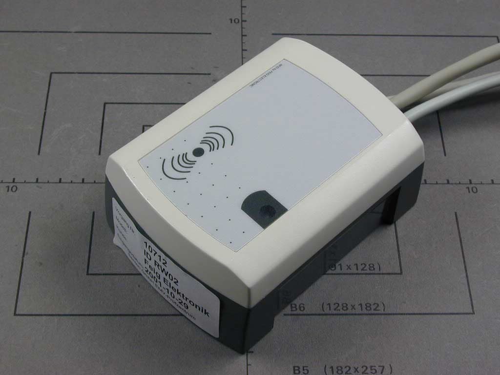
Click to zoom
Application Details
- Equipment Class
- DCD - Part 15 Low Power Transmitter Below 1705 kHz
- Date of Grant
- Dec 09, 2003
- Application Purpose
- Original Equipment
- Date of Application
- Dec 09, 2003
- Equipment Note
- Inductive Reader
- Frequency Range
- 0.12500000 - 0.12500000
- Company
- Feig Electronic GmbH
- Country
- Germany
Documents & Files
Document Text
Text extracted from the exhibit documents filed with the FCC. Open a document above to read the original.
Users Manual
OBID ® InstallationID RW02.ABC FEIG ELECTRONIC GmbHPage1of18 E N G L I S H ID RW02.ABC-A(RS232 Interface) ID RW02.ABC-B(RS485 Interface) (english) OBID ® InstallationID RW02.ABC Page2of18FEIG ELECTRONIC GmbH E N G L I S H Note Copyright1999 - 2002by FEIG ELECTRONIC GmbH LangeStrasse 4 D-35781 Weilburg-Waldhausen Tel.: +49 6471 3109-0 http://www.feig.de With the edition of this document, all previous editions become void. Indications made in this manual may be changed without previous notice. Copying of this document, and giving it to others and the use or communication of the contents thereof are forbidden without express authority. Offenders are liable to the payment of damages. All rights are reserved in the event of the grant of a patent or the registration of a utility model or design. Composition of the information in this document has been done to the best of our knowledge. FEIG ELEC- TRONIC GmbH does not guarantee the correctness and completeness of the details given in this manual and may not be held liable for damages ensuing from incorrect or incomplete information. Since, despite all our efforts, errors may not be completely avoided, we are always grateful for your useful advises. The instructions given in this manual are based on advantageous boundary conditions. FEIG ELECTRONIC GmbH does not give any guarantee promise for perfect function in cross environments. FEIG ELECTRONIC GmbH assumes no responsibility for the use of any information contained in this document and makes no representation that they free of patent infringement. FEIG ELECTRONIC GmbH does not convey any license under its patent rights nor the rights of others. OBID ® is registered trademark of FEIG ELECTRONIC GmbH. General information's regarding this document The sign "F" indicates extensions or changes of this manual compared with the former issue. OBID ® InstallationID RW02.ABC FEIG ELECTRONIC GmbHPage3of18 E N G L I S H Content 1.Safety instructions4 2.Installation5 2.1Installation on flush-mounting box...........................................................................6 2.2Installation with surface frame ID APR-A..................................................................7 3.Reader-connection8 3.1(F) Jumper and Switches..........................................................................................9 3.2Power supply.............................................................................................................10 3.3Relay..........................................................................................................................10 3.4Digital inputs (IN1 / IN2)............................................................................................10 3.5RS232 Interface (ID RW02.ABC-A)...........................................................................10 3.6(F) RS485 Interface (ID RW02.ABC-B)....................................................................11 3.7(F) Data-/Clock interface..........................................................................................12 4.Operation13 4.1Address setting (Bus mode with RS485 interface).................................................13 5.(F) Technical data14 5.1Approval....................................................................................................................15 5.2USA (FCC)..................................................................................................................15 5.3Dimensions for concealed installation....................................................................16 5.4Dimensions for surface installation with ID APR-A................................................17 6.System delivery contents:18 6.1Optional Accessories...............................................................................................18 OBID ® InstallationID RW02.ABC Page4of18FEIG ELECTRONIC GmbH E N G L I S H 1.Safety instructions •The device has to be used only for the purpose designed by the manufacturer. •The operation manual has to be stored available at any time and has to be handed over to each user. •Unauthorized changes and the use of spare parts and additional devices which have not been sold or recommended by the manufacturer may cause fire, electric shocks or injuries. Such measures will lead to exclusion of any liability by the manufacturer. •The liability-prescriptions of the manufacturer in the issue valid at the time of purchase are valid for the device. The manufacturer is not legally responsible for incorrect, unsuitable manual orautomatical setting of parameters for a device or the incorrect application of a device. •Repairs can only be executed by the manufacturer. •Installation-, operation- and maintenance procedures should only be carried out by qualified personnel. •Before opening the device, the power supply must always be interrupted. Make sure that the device is without voltage by measuring. CAUTION! The fading of an operation control (LED) is no indicator for an interrupted power supply or the device being without voltage! •Works at the device and its installation have to be executed according to the national legal requirements and local prescriptions. •When working on devices the valid safety regulations must be observed. OBID ® InstallationID RW02.ABC FEIG ELECTRONIC GmbHPage5of18 E N G L I S H 2.Installation The Reader has been designed for wall installation on 60mm flush-mounting box. For surface installation, the bottom part of the casing can be substituted by the surface frame IDAPR-A, which is available as an attachment. NOTES: •The Reader must not be installed directly upon conductive materials as e.g. metal sur- faces, metal grids (reinforcements) ormetallized surfaces, as these surfaces reduce the detection range of the Reader. The distance between the Reader and such surfaces should be min. 3 cm. If an installation to a metal surface becomes necessary, the surface frame IDAPR-A can be employed in order to keep the minim…
Text truncated - open the document above for the full version.
Cover Letter(s)
Request for Confidentiality 09 December 2003 PHOENIX TEST-LAB GmbH Königswinkel 10 D32825 Blomberg Germany RE: Certification Application FCC ID: PJMRW02 Please be advised that the following information is to be held confidential on behalf of FEIG ELECTRONIC GmbH • Schematics • Parts Lists • Block Diagram • Technical Description The application contains technical information which FEIG ELECTRONIC GmbH deems to be trade secrets and proprietary. If made public, the information might be used to the disadvantage of the applicant in the market place. Thank you for your attention to this matter. Signatory
External Photos
EMV-Pr ̧fzentrum EMI/EMC-Testcenter FCC ID: PJMRW02 Front of Unit EMV-Pr ̧fzentrum EMI/EMC-Testcenter FCC ID: PJMRW02 Rear of Unit
ID Label/Location Info
This device complies with Part 15 of the FCC Rules, Operation is subject to the following two conditions: (1) this device may not cause harmful interference and (2) this device must accept any interference received, including interference that may cause undesired operation.
Internal Photos
EMV-Pr ̧fzentrum EMI/EMC-Testcenter FCC ID: PJMRW02 Unit disassembled EMV-Pr ̧fzentrum EMI/EMC-Testcenter FCC ID: PJMRW02 Top of Printed Board EMV-Pr ̧fzentrum EMI/EMC-Testcenter FCC ID: PJMRW02 Rear of Printed Board
Test Report
EMV-PrüfzentrumEMI/EMC-Testcenter FCC-ID: PJMRW02 Test Report No. 50602-30261 Page 1 of 17 Pages Straubing, 8 December 2003 T E S T - R E P O R T No. 50602-30261 for ID RW02 Inductive Reader Applicant: FEIG ELECTRONIC GmbH Test Specification: FCC Code of Federal Regulations, CFR 47, Part 15, Section 15.209 Note: The test data of this report relate only to the individual item which has been tested. This report shall not be reproduced except in full extent without the written approval of the testing laboratory. EMV-PrüfzentrumEMI/EMC-Testcenter FCC-ID: PJMRW02 Test Report No. 50602-30261 Page 2 of 17 Pages Table of Contents 1. Administrative Data....................................................................................3 2. Identification of Test Laboratory.................................................................4 3. Operation Mode of EUT.............................................................................5 4. Configuration..............................................................................................6 5. Measuring Methods...................................................................................7 5.1. Radiated Emission Measurement 9 kHz – 30 MHz.............................7 5.2. Field Strength of Emissions, Prescans in a fully-anechoic Room...................................................................................................8 5.3. Radiated Emission Measurement at Open Area Test Site..................9 6. Photographs Taken During Testing.........................................................10 7. List of Measurements...............................................................................13 8. Referenced Regulations..........................................................................16 Charts taken during testing...............................................................................17 EMV-PrüfzentrumEMI/EMC-Testcenter FCC-ID: PJMRW02 Test Report No. 50602-30261 Page 3 of 17 Pages 1. Administrative Data Test item (EUT) Type designation ID RW02 Serial number(s): 001 Type of equipment: Inductive Reader Parts/accessories: FCC-ID: PJMRW02 Technical data Frequency range 0.125 MHz Operational frequencies N/A Type of modulation 10K0A1D Pulse frequency N/A Pulse width N/A Antenna Integrated Power supply 12 - 24 V AC / DC Applicant: (full address) FEIG ELECTRONIC GmbH Lange Strasse 4 D-35781 Weilburg-Waldhausen Contract identification: --- Contact person: Bernhard Schuessler Manufacturer: FEIG ELECTRONIC GmbH Application details Receipt of EUT: 22 April 2003 Date of test: December 2003 Note: Responsible for testing: Martin Steindl Responsible for test report: Martin Steindl EMV-PrüfzentrumEMI/EMC-Testcenter FCC-ID: PJMRW02 Test Report No. 50602-30261 Page 4 of 17 Pages 2. Identification of Test Laboratory DETAILS OF THE TEST LABORATORY COMPANY NAME: Senton GmbH EMI/EMC Test Center ADDRESS: Aeussere Fruehlingsstrasse 45 D-94315 Straubing Germany LABORATORY ACCREDITATION: DAR-Registration No. TTI-P-G 062/94-01 FCC TEST SITE LISTING INDUSTRY CANADA TEST SITE REGISTRATION IC 3050 NAME FOR CONTACT PURPOSES: Mr. Johann Roidt TELEPHONE: (+49) (0)9421 5522-0 FAX: (+49) (0)9421 5522-99 PERSONNEL INVOLVED IN THIS TEST REPORT TECHNICAL DIRECTOR: Mr. Johann Roidt RESPONSIBLE FOR TESTING: Mr. Johann Roidt RESPONSIBLE FOR TEST REPORT: Mr. Johann Roidt SUMMARY OF TEST RESULTS The tested sample complies with the requirements set forth in the Code of Regulations CFR 47, Part 15, Section 15.209 EMV-PrüfzentrumEMI/EMC-Testcenter FCC-ID: PJMRW02 Test Report No. 50602-30261 Page 5 of 17 Pages 3. Operation Mode of EUT Continuously reading a transponder card. EMV-PrüfzentrumEMI/EMC-Testcenter FCC-ID: PJMRW02 Test Report No. 50602-30261 Page 6 of 17 Pages 4. Configuration Configuration of the EUT Not applicable Cables connected to the EUT Not applicable Peripheral devices connected to the EUT Not applicable EMV-PrüfzentrumEMI/EMC-Testcenter FCC-ID: PJMRW02 Test Report No. 50602-30261 Page 7 of 17 Pages 5. Measuring Methods 5.1. Radiated Emission Measurement 9 kHz – 30 MHz Rules and Specifications: Sections 15.109 & 15.209 Guide: ANSI C63.4 1997 Measurement Procedure: Radiated emissions in the frequency range 9 kHz – 30 MHz were measured initially at a distance of 3 meters. A prescan at 3 meter distance were performed in a shielded room with the detector of the spectrum analyzer or EMI Receiver set to peak. Hand-held or body-worn devices are rotated through three orthogonal axes to determine which attitude and configuration produces the highest emission relative to the limit and therefore shall be used for final testing. Final measurement is then performed at 30 meter distance. In case the regulation requires testing at other distances, the result will be extrapolated. The extrapolation factor is determined by making a second measurement at 10 meter distance. In cases of very low emissions measurements are performed at shorter distances and results are extrapolated to the required distance. The provisions of 15.31 (d) apply. According to section 15.209 (d) final measurementis performed with the detector set to Quasi Peak except for the frequency bands 9 – 90 kHz and 110 – 490 kHz where average detector is employed. Test instruments used: No. Type Model Serial Number Manufacturer 01 Test receiver ESH 3 880112/032 Rohde & Schwarz 02 Loop antenna HFH2-Z2 882964/1 Rohde & Schwarz 03 Open Field Test Site No. 1 N/A Senton EMI Receiver EUT 30 m test distance EMV-PrüfzentrumEMI/EMC-Testcenter FCC-ID: PJMRW02 Test Report No. 50602-30261 Page 8 of 17 Pages 5.2. Field Strength of Emissions, Prescans in a fully-anechoic Room Rules and Specifications: Sections 15.109 & 15.209 Guide: ANSI C63.4 1997 Measurement Procedure: Radiated emissions are measured over the frequency range from 30 MHz to the 5 th harmonic of the maximum frequency of the EUT. Measurements were made in both the horizontal and vertical planes of polarization in a fully anechoic room usin…
Text truncated - open the document above for the full version.
Test Setup Photos
EMV-PrüfzentrumEMI/EMC-Testcenter FCC-ID: PJMRW02 Test Report No. 50602-30261 Page 11 of 17 Pages Test setup for radiated emission measurement 9 kHz – 30 MHz EMV-PrüfzentrumEMI/EMC-Testcenter FCC-ID: PJMRW02 Test Report No. 50602-30261 Page 12 of 17 Pages Test setup for radiated emission measurement (fully anechoic room)
Contact Information
Applicant
Elmar Reichwein(Manager)
Technical Contact
Senton GmbHJohann Roidt
[email protected]+49 9421 55 22 13
Aeussere Fruehlingsstrasse 45 · Straubing · Germany
Non-Technical Contact
Senton GmbHJohann Roidt
[email protected]+49 9421 55 22 13
Test Firm
TUV SUD Product Service GmbH PS-EMC-STRRainer Heller
Technical Specifications
| # | Rule Parts | Frequency Range | Power Output |
|---|---|---|---|
| 1 | 15C | 0.125 MHz - 0.125 MHz | - |
Other Applications from Feig Electronic GmbH

PJMPRM103
Feb 25, 2026RFID Reader
Equipment Class
DXX - Part 15 Low Power Communication Device Transmitter
PJMMRM103
Jan 19, 2026RFID Reader
Equipment Class
DXX - Part 15 Low Power Communication Device TransmitterPJMTSTFSAMC
Dec 01, 2024Wireless Safety System for industrial doors - Mobile Unit
Equipment Class
DXX - Part 15 Low Power Communication Device Transmitter
PJMLRM5400
Jun 27, 2023RFID Reader
Equipment Class
DXX - Part 15 Low Power Communication Device Transmitter
PJMMRU102A
Jul 07, 2021RFID Reader
Equipment Class
DSS - Part 15 Spread Spectrum Transmitter