PJQ-TRACER-25Wireless Hands Free Windows Pointer System
Boost Technology, LLC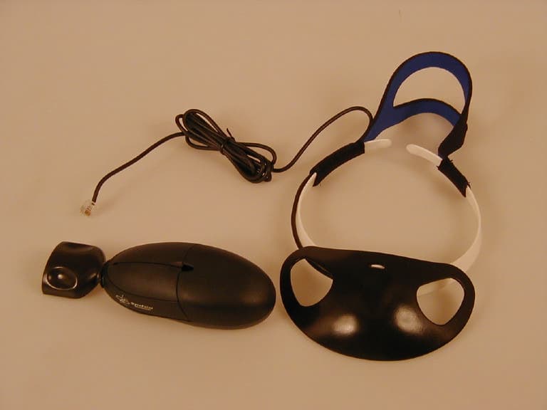
Click to zoom
Application Details
- Equipment Class
- DXX - Part 15 Low Power Communication Device Transmitter
- Date of Grant
- Apr 03, 2001
- Application Purpose
- Original Equipment
- Date of Application
- Apr 03, 2001
- Equipment Note
- Wireless Hands Free Windows Pointer System
- Frequency Range
- 49.82000000 - 49.90000000
- Company
- Boost Technology, LLC
- Country
- United States
Documents & Files

Document Text
Text extracted from the exhibit documents filed with the FCC. Open a document above to read the original.
Users Manual
TRACER User Instructions Boost Technology, LLC 1712 Ocean Avenue San Francisco, California 94112 www.boosttechnology.com 76-000025-19 Rev. 1 Tracer Page 2 of 18Boost Technology Table of Contents About Tracer™..................................................................................................................................3 Using Tracer .....................................................................................................................................5 The Transmitter ............................................................................................................................5 The Visor..................................................................................................................................7 For Hands-Free Mousing .........................................................................................................8 For Desktop Use ......................................................................................................................8 In Use Cradle ...........................................................................................................................9 Care and Maintenance....................................................................................................................11 Installing or Removing the Batteries ...........................................................................................12 Recharging .............................................................................................................................13 Resetting the Tracer ...................................................................................................................13 Transmitter .............................................................................................................................13 Receiver .................................................................................................................................14 Resetting Transmitter ID.............................................................................................................14 On-The-Fly RF Channel Changing .............................................................................................14 Troubleshooting Guide....................................................................................................................15 Regulatory Information....................................................................................................................17 Contacting Boost ........................................................................................................................18 Boost's Guarantee ......................................................................................................................18 Tracer Boost TechnologyPage 3 of 18 About Tracer™ Thank you for purchasing Tracer™, a whole new kind of mouse you control by moving your head. Tracer uses GyroPoint Technology™, based on a solid-state sensor that detects your natural head motions to precisely control the cursor on the screen! Because its patented micro-gyroscope technology is remarkably precise — down to individual pixel resolution — anything that can be done with a mouse, you can do with Tracer. Follow this guide to easily install and use the Tracer. Please refer to the figure below to familiarize yourself with the parts of the Tracer system: Tracer Page 4 of 18Boost Technology Installing Tracer Installing Tracer is quick and simple. Please refer to the illustration on the preceding page: 1. Make sure you have a Microsoft, Logitech or compatible mouse driver installed on your computer. Refer to your operating system's documentation for details about driver verification and installation. 2. Plug the AC adapter into a power outlet and insert power plug into the back of the receiver. Note - The AC adapter is required to charge the NiMH battery in the transmitter. Once the transmitter is charged, the AC adapter may be disconnected, if desired. The AC adapter needs to be connected to the receiver when charging of the battery is required. Disconnecting the AC adapter may also reduce the reception range. 3. Install NiMH battery into Tracer transmitter (see "Installing or Removing Batteries" below) 4. Allow Tracer to charge in cradle for 14 hours. 5. Turn off your computer. 6. Connect theTracer receiver cable to your computer by one of the following methods: a. Directly connect the PS2 plug on the receiver to the PS2 port on the rear of your computer. b. If you use a PC that does not have a PS2 port, connect the receiver to either the RS-232 serial port or a USB port using the appropriate adapter. c. If you are using an Apple Macintosh with an ADB jack, use the appropriate adapter and load the driver software as instructed in the README file on the included diskette. d. If you are using an Apple Macintosh with a USB jack, connect the receiver to the USB jack using the appropriate adapter Refer to your computer's instruction manual to locate the correct port. The adapter you specified when ordering the Tracer will have been included in your shipment. 7. Power on computer Note - Receiver must be at least 12 inches from any significant electromagnetic source (e.g., monitor). Tracer Boost TechnologyPage 5 of 18 Using Tracer The Transmitter Note - The transmitter must be placed on the receiver cradle before initial use. If it was not, place the transmitter in the cradle until the transmitter LED blinks at least once, to allow the system to synchronize properly. Familiarize yourself with the features of the transmitter: The LED indicates the activity of the transmitter. If the LED is lit, the transmitter is on. If the LED is blinking and/or dim, the transmitter battery needs to be recharged soon. If the LED is dark, the transmitter is either in "sleep" mode, or the battery is dead. Press any button to wake up the transmitter. If the LED remains dark, return the…
Text truncated - open the document above for the full version.
Operational Description
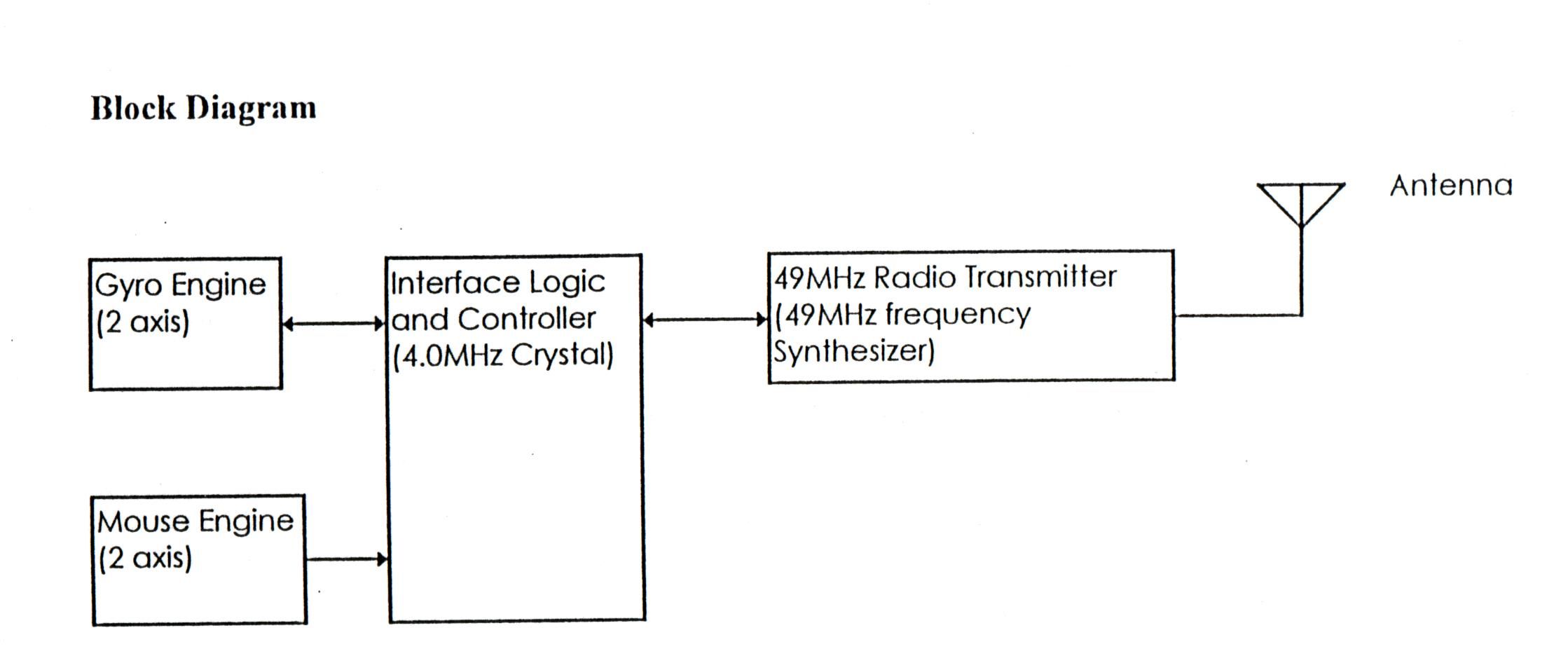
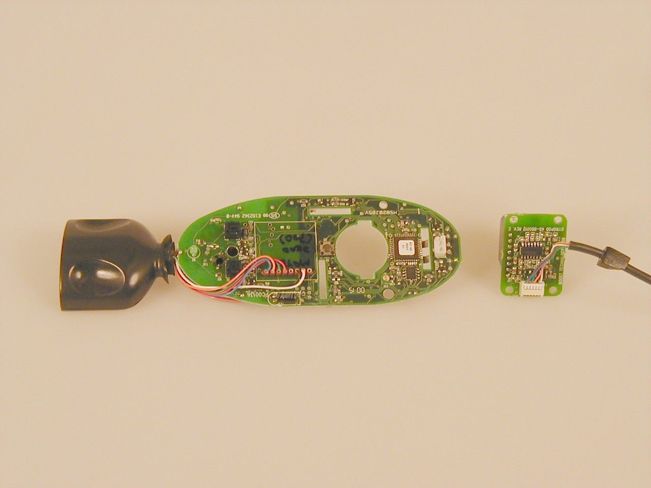
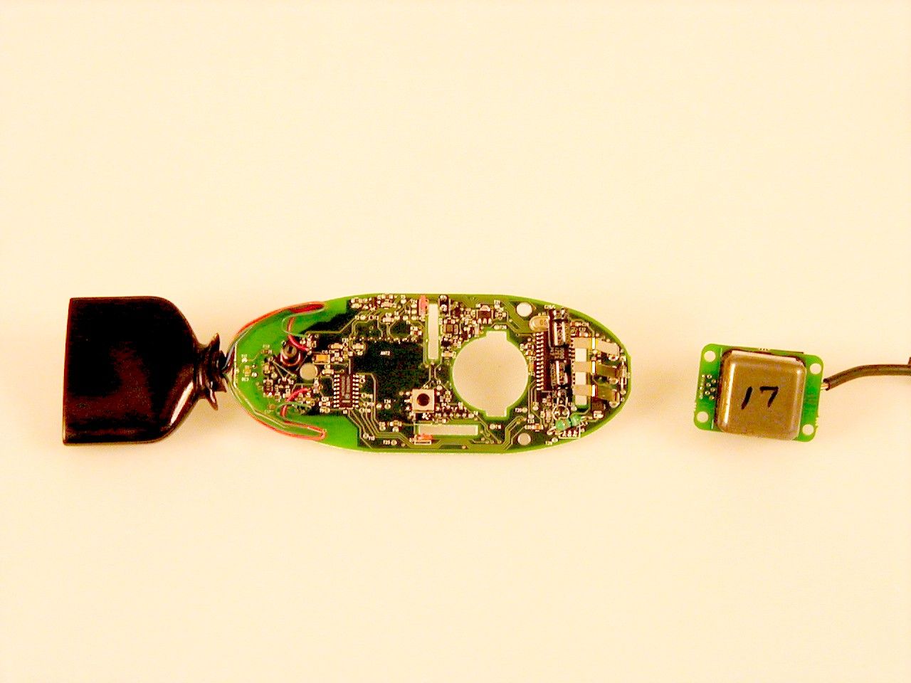
PJQ-TRACER-25 Attachment 2 1 of 6 Product Description for "Tracer" Summary The Boost "Tracer" product consists of an aftermarket modification to a component of the GP9450 system ("Acrobat") manufactured by Gyration, Incorporated. The GP9450 is a wireless computer mouse. Outlined below are the physical charateristics of the "Tracer" system, including an enumeration of the differences between the final Boost product and the previously tested GP9450-H (the "HANDSET", FCC ID JJ4GP9450-H). Physical Specs Tracer Specifications Receiver* Handset Visor Size (inches) 2.6W X 5.5L X 2.7H 2.2W X 6.7L X 1.7H 5.5W X 8.5L X 2H Weight (ounces) 6 6.5 6 Cable Length (feet) 6 - 6 Operating Range - Up to 15 feet (4.57 m) from receiver (not limited to line of sight) - Radio Multi-channel (7) FM (US 49 MHz), 16 addresses - Operating Temperature +10° to 40°C (+50° to 104° F) Storage Temperature -30° to 70°C (-22° to 158° F) Power Supply 120V AC/ 6V DC adapter included Rechargable NiMH battery included (minimum 9 hours continuous use on full charge) Input Jacks - 1. Two 1/8 inch (3mm) mono audio jacks (for external buttons) 2. One RJ11 jack (for Visor input) - Hardware Compatability ♦ IBM PS2, PC/AT, and compatibles • PS/2 Mouse Port • DB-9 Serial Port • USB Port (optional adapter required) ♦ Apple Macintosh • USB Port (optional adapter required) • ADB Port (optional adapter AND software required) OS compatability ♦ MS-DOS 3.x or later ♦ Windows 3.1,95/98,NT, 2000 (with Microsoft, Logitech, or compatible mouse driver) ♦ Macintosh OS 8 or later ♦ Any other OS with HID device support * Previously submitted as JJ4-GP9450-R Theory of Operation Positional data are gathered by one of two means: the default Gyro Engine, which responds to analog voltages induced by Pitch and Yaw of a gyroscopic PJQ-TRACER-25 Attachment 2 2 of 6 sensor; or from a Standard Mouse Engine, detecting counts from ball-driven X / Y encoders on the transmitter. This data is passed to microcontroller-based Interface Logic, which formats the Positional Data as packets and passes it to a 49MHz radio transmitter, which modulates the 49MHz signal as ON-OFF keying to encode and transmit the data. The "Tracer" is designed to be used in two different configurations- 1) Use as a hands-free computer mouse: The transmitter will be attached to the users chair, with the gyro module connected via cable tether and worn on the users head. 2) Use as a "normal" wireless mouse: The handset will be placed upon the table top and used as a regular mouse. This is possible both with and without the cable tether attached. Modifications to GP9450 As previously stated, aftermarket modification of the Gyration GP9450 Acrobat system, FCC ID JJ4GP9450-H yields the Transmitter and Visor devices mentioned above. Details of the modifications are given below: - The original device is shown here with a portion of the housing removed. The gyroscopic sensor, the cubic metal can seen protruding here, is removed and enclosed in a separate housing (see below). PJQ-TRACER-25 Attachment 2 3 of 6 - A connector is attached to the front of the original PVC housing. The connector will be PVC with a PET core. The assembly is seen below with the top half of the original housing removed. The complete unit is shown in the inset. The PET core protects an internal PCB supporting two audio and one RJ-11 jack, as well a six SMT jumpers. Wires will lead from the rear of the connector to the various solder contacts on the orignal PCB. The following picture shows the connector PCB in its uncoated form, as well as in a prototype overmold. Below the 10 connections to the various locations on the PCB are shown. Note the antenna (the curved metal plane) in the right hand image: PJQ-TRACER-25 Attachment 2 4 of 6 The wire connections above as well as details regarding two component changes are shown on the attached schematics. C37 has been added (a shunt capacitor for Switch 2), which has no effect on the antenna system, and inductor L2 (seen above as the copper coil in the right hand picture) has been changed from a variable inductor with 2.56-3.8uH range to one with a 0.9-1.9uH range. - The gyroscope sensor module is mounting in a remote housing made of ABS. This is connected to the handset via a six-foot long cable tether, a six conductor (28AWG, 7/32) cable with a capacitance of <23pF/ linear foot. The assembly is shown here with the cover on and off: PJQ-TRACER-25 Attachment 2 5 of 6 The gyroscope is installed on a PCB board that amplifies the output voltage to overcome line resistance and maintain a clean analog signal at the transmitter. The PCB also supports SMT bead core inductors to filter RF introduced into the cable from the transmitter antenna. Cable is terminated with a molex connection at one end (header shown below), and an RJ-11 plug at the other. PJQ-TRACER-25 Attachment 2 6 of 6
Test Report
File: R42499 March 19, 2001 American Telecommunications Certification Body, Inc. 6731 Whittier Avenue McLean, VA. 22101 Gentlemen: The enclosed documents constitute a formal submittal and application for a Grant of Equipment Authorization pursuant to Subpart C of Part 15 of FCC Rules (CFR 47) regarding intentional radiators. Data within this report demonstrates that the equipment tested complies with the FCC limits for intentional radiators. Elliott Laboratories, as duly authorized agent prepared this submittal. A copy of the letter of our appointment as agent is enclosed. If there are any questions or if further information is needed, please contact Elliott Laboratories for assistance. Sincerely, David W. Bare Chief Technical Officer DWB/dmg Enclosures: Agent Authorization Letter Emissions Test Report with Exhibits File: R42499 Page 1 of 14 Electromagnetic Emissions Test Report and Application for Grant of Equipment Authorization pursuant to FCC Part 15, Subpart C Specifications for an Intentional Radiator on the Boost Technology Model: Tracer FCC ID: PJQ-TRACER-25 GRANTEE: Boost Technology 1712 Ocean Ave. San Francisco, CA. 94112 TEST SITE: Elliott Laboratories, Inc. 684 W. Maude Avenue Sunnyvale, CA 94086 REPORT DATE: March 19, 2001 FINAL TEST DATE: March 8, 2001 AUTHORIZED SIGNATORY: ______________________________ David W. Bare Chief Technical Officer This report shall not be reproduced, except in its entirety, without the written approval of Elliott Laboratories, Inc. Elliott Laboratories, Inc. -- EMC Department Test Report Report Date: March 19, 2001 File: R42499 Page 2 of 14 pages TABLE OF CONTENTS COVER PAGE.....................................................................................................................................................1 TABLE OF CONTENTS...................................................................................................................................2 SCOPE...............................................................................................................................................................4 OBJECTIVE......................................................................................................................................................4 STATEMENT OF COMPLIANCE...................................................................................................................4 EMISSION TEST RESULTS............................................................................................................................5 LIMITS OF CONDUCTED INTERFERENCE VOLTAGE.............................................................................5 LIMITS OF RADIATED INTERFERENCE FIELD STRENGTH...................................................................5 MEASUREMENT UNCERTAINTIES............................................................................................................5 EQUIPMENT UNDER TEST (EUT) DETAILS..............................................................................................6 GENERAL......................................................................................................................................................6 OTHER EUT DETAILS..................................................................................................................................6 ENCLOSURE.................................................................................................................................................6 MODIFICATIONS..........................................................................................................................................6 SUPPORT EQUIPMENT................................................................................................................................6 EUT INTERFACE PORTS..............................................................................................................................7 EUT OPERATION..........................................................................................................................................7 TEST SITE.........................................................................................................................................................8 GENERAL INFORMATION..........................................................................................................................8 CONDUCTED EMISSIONS CONSIDERATIONS.........................................................................................8 RADIATED EMISSIONS CONSIDERATIONS.............................................................................................8 MEASUREMENT INSTRUMENTATION......................................................................................................9 RECEIVER SYSTEM.....................................................................................................................................9 INSTRUMENT CONTROL COMPUTER.......................................................................................................9 LINE IMPEDANCE STABILIZATION NETWORK (LISN)..........................................................................9 FILTERS/ATTENUATORS..........................................................................................................................10 ANTENNAS.................................................................................................................................................10 ANTENNA MAST AND EQUIPMENT TURNTABLE................................................................................10 INSTRUMENT CALIBRATION...................................................................................................................10 TEST PROCEDURES.....................................................................................................................................11 EUT AND CABLE PLACEMENT......................................................…
Text truncated - open the document above for the full version.
Test Setup Photos
Elliott Laboratories, Inc. -- EMC Department Test Report Report Date: March 19, 2001 File: R42499 Page 1 of 2 Pages EXHIBIT 3: Radiated Emissions Test Configuration Photographs Elliott Laboratories, Inc. -- EMC Department Test Report Report Date: March 19, 2001 File: R42499 Page 2 of 2 Pages EXHIBIT 3: Radiated Emissions Test Configuration Photographs
Contact Information
Applicant
Charles E Schmelz(Chief Operations Officer)
Technical Contact
Elliott Laboratories, Inc.David W Bare
[email protected]408 245 7800
684 West Maude Ave · Sunnyvale, California · United States
Test Firm
Elliott Laboratories LLCDavid Bare
Technical Specifications
| # | Rule Parts | Frequency Range | Power Output |
|---|---|---|---|
| 1 | 15C | 49.82 MHz - 49.9 MHz | - |