PLC500AWater Sensor
Custom Assemblies Ltd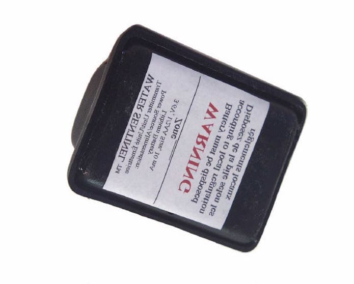
Click to zoom
Application Details
- Equipment Class
- DXX - Part 15 Low Power Communication Device Transmitter
- Date of Grant
- Jul 24, 2001
- Application Purpose
- Original Equipment
- Date of Application
- Apr 10, 2001
- Equipment Note
- Water Sensor
- Frequency Range
- 916.50000000 - 916.50000000
- Company
- Custom Assemblies Ltd
- Country
- Canada
Documents & Files
Document Text
Text extracted from the exhibit documents filed with the FCC. Open a document above to read the original.
Users Manual
Water Sentinel System Operational Description Rev.03 WARNING: Changes or modifications not expressly approved by Custom Assemblies Ltd. could void the user’s authority to operate the equipment. The Water Sentinel is an advanced RF controller designed to control the restriction of water in the home due to water leakage. This unit is based on a small RISC based microcontroller, and a RF receiver, along with control circuit and relay to control a normally closed valve. Each Water Sentinel is capable of handling up to 6 different zones, separately indicated by an LED. Each water sensor transmitter has its own unique electronic identification number, in this way the Water Sentinel can be taught to recognize different zones. The water sensor transmitters are equipped with a RISC based micro controller along with a transmitter, the transmitters are hybrid modules, designed to transmit at particular frequencies, this is to insure reliable transmissions when required. Sensors remain without power, until water is sensed with the probes. Sensor unit now becomes powered, sends 3 consecutive messages, for increased reliability, and then goes into a sleep mode for 2 seconds, (to conserve power) then retransmits again, this cycle continues until water is removed from sensor. Power consumption is extremely small, in the order of 10ma when fully transmitting, and less then 200uA in sleep mode. The Water Sentinel Receiver is equipped with a RF receiver (hybrid), when this receiver detects the proper sensor signal, it removes power from the relay, this relay in turn removes power from the water valve which is always on. The relay will remain off until it no longer receives a signal and for a time delay of thirty seconds or until someone presses PROG/RESET. In addition to its normal function, the water sentinel keeps track of how long it has been energized, when 24 hours is reached the water sentinel removes power from relay for a few seconds, then restores power. This prevents valve from sticking, by the daily cycling of it. This unit is also equipped with an interface for an automatic dialer unit (upcoming option). There is also an interface for an optional temperature sensor that will shut water off in the event of freeze conditions. Water Sentinel System 2 Also incorporated into unit, is the ability to change firmware code without having to replace board or chip, all programming can be done on board, even in the field. This device complies with part 15 of the FCC Rules. Operation is subject to the following two conditions: (1) this device may not cause harmful interference and (2) this device must accept any interference received, including interference that may cause undesired operation. Note: This equipment has been tested and found to comply with the limits for a class B digital devices, pursuant to part 15 of the FCC Rules. These limits are designed to provide reasonable protection against harmful interference in a residential installation. This equipment generates, uses, and can radiate radio frequency energy and, if not installed and used in accordance with the instruction manual, may cause harmful interference to radio communications. However, there is no guarantee that interference will not occur in a particular installation. If this equipment does cause harmful interference to radio or television reception, which can be determined by turning the equipment off and on, the user is encourage to try to correct the interference by one of more of the following measures: - Reorient or relocate the receiving antenna - Increase the separation between the equipment and reveiver - Connect the equipment into an outlet on a circuit different from that to which the receiver is connected. - Consult the dealer or an experienced radio/TV technician for help. Water Sentinel System 3 Water Sentinel System Installation Procedure Rev.03 Initial Setup & Programming of Water Sentinel System: 1) Do not install water sensors until the unit is plugged in, plumbing has been installed, and the programming is complete. 2) To program press the PROG/RESET button once, LED LIGHT 1 should come on, with #1 LED lit, short water sensor probes together with wire or sponge with water. The LED will go out indicating that the receiver got the water sensor signal and position #1 is programmed with the unique code, by pressing the PROG/RESET button again, until next position is lit, you can continue to program remainder of the units in the same manner. 3) Once the water sensors are programmed into the Water Sentinel, install sensors in their proper locations. The LED’s should be labeled to reference these locations. 4) Verify proper operation of each sensor by shorting with a sponge with water, this insures proper sensitivity to water. 5) When Unit is beeping, the PROG/RESET button can be pressed to shut signal off, or after 30 seconds unit will shut off provided that there is no more water detected. Water Sentinel System 4 Electrical Specifications Water Sensor Transmitters Internal battery operated. Voltage 3.6 Volts ½ AA size. Current: Less than 1ua in standby mode, no water detected. Water Detected: 10mA Transmitting for less than 50 milliseconds every 2 seconds. At one test every month, at an average of two seconds run per test, this would be a 10 ma for 24 seconds/year. This is less than the self-discharge rate of the battery. The self-discharge rate of the battery is 2%/year. Based on this, the battery would last at least 12 years. Water Sentinel Receiver Unit Volts: 110/120 Volts A.C. Wattage: 10 WATTS Safety: Electronics, 0.1 Amp slo-blow Fuse. Valve: Direct Connection Operating Frequency: 916.5 MHz OOK Modulation. 8 byte (64 bit) address fields unlimited unique id number, 16 bit CRC checking.
Cover Letter(s)
2 3000 Bristol Circle, Oakville, Ontario, Canada L6H 6G4 Telephone (905) 829-1570 Facsimile (905) 829-8050 Website: www.ultratech-labs.com Email: [email protected] UltraTech Group of Labs March 26, 2001 FEDERAL COMMUNICATIONS COMMISSION 7435 Oakland Mills Road Columbia, MD 21046 USA Subject: Certification Application under FCC Part 15, Subpart C, Para. 15.249, Low Power Transmitters Operating in the Frequency Band 902-928 MHz. Applicant: Custom Assemblies Ltd. Product: Water Sentinel Model: WS500A FCC ID: PLC500A Dear Sir/Madam, As appointed agent for Custom Assemblies Ltd.., we would like to submit the application to the Federal Communications Commission for certification of the above product. Please review all necessary files uploaded to FCC OET site for detailed information. If you have any queries, please do not hesitate to contact us by our TOLL FREE number: OUR TELEPHONE NO.: 1-877-765-4173 Yours truly, Tri Minh Luu, P. Eng., V.P., Engineering TML/MT Encl.
Cover Letter(s)
2001-03-19 FEDERAL COMMUNICATIONS COMMISSION 7435 Oakland Mills Road Columbia, MD 21046 U.S.A. Subject: Authority to Act as an Agent to FCC Applicant: Custom Assemblies Ltd. Product: Water Sentinel Model: WS500A FCC ID: PLC500A Dear Sir/Madam, I hereby appoint UltraTech Engineering Labs Inc. (UltraTech) to act as my agent in preparation of this application to F.C.C. for authorization of equipment under F.C.C. Rules. I also certify that the information provided, properly described the device or system for which authorization is required. Regards Francois Boudreau, EIT Water Sentinel Project Manager Custom Assemblies
Cover Letter(s)
2001-03-28 FEDERAL COMMUNICATIONS COMMISSION 7435 Oakland Mills Road Columbia, MD 21046 U.S.A. Subject: Request for withholding from public disclosure the schematic diagrams and system block diagrams pursuant to an application for certification. Applicant: Custom Assemblies Ltd. Product: Water Sentinel Model: WS500A FCC ID: PLC500A Dear Sir/Madam, We, Custom Assemblies Ltd., would like to request that the system block diagram, schematic diagrams and Parts List, submitted with the application for certification be withheld from public disclosure as per Section 0.459 of FCC Rules. This request is made under the provisions of Section 0.457(d) of the Commission's Rules, and Section 552(b)(4) of the Freedom of Information Act. These sections authorize as a withholding from public inspection materials which would be privileged as a matter of law if retained by the person submitting them, and materials which would not customarily be released to the public by that person. The detailed confidential materials are listed as follows: No. Title Drawing No. Sheet No. 1 Schematics 2 Parts List 3 Block Diagram If you have any queries, please do not hesitate to contact us, our numbers: OUR TELEPHONE NO.: (506) 858-7817 (506) 877-0735 Yours truly, Francois Boudreau, EIT Water Sentinel Project Manager Custom Assemblies.
External Photos
EXHIBIT 10 – EXTERNAL PHOTOGRAPHS TRANSMITTER – FRONT TRANSMITTER - BACK
ID Label/Location Info
To Whom It May Concern: The following is the actual label layout that will be used on all transmitter units. This label shall be located on the rear of the transmitter located just below the existing label. Label dimensions: 1.65” x 2.25” Back of Water Sentinel Transmitter Unit Regards, Francois Boudreau, EIT Project Manager, Water Sentinel Custom Assemblies 506-877-0735 [email protected] LABEL WATER SENTINEL TM CUSTOM ASSEMBLIES LTD Canada, New Brunswick Transmitter Unit/Unite Emetrice Model/Modele: WS500A Serial Number/Numero Serie: 00001 FCCID: ___-500A Made in Canada/Fabriquer au Canada ZONE______ Power Source/Alimentation: Lithium Battery 3.6V, 1/2AA Size, 10mA WARNING Battery must be disposed according to local regulation. Disposez de la pileselon les reglements locaux.
ID Label/Location Info
To Whom It May Concern: The following is the actual label layout that will be used on all transmitter units. This label shall be located on the rear of the transmitter located just below the existing label. Label dimensions: 1.65” x 2.25” Back of Water Sentinel Transmitter Unit Regards, Francois Boudreau, EIT Project Manager, Water Sentinel Custom Assemblies 506-877-0735 [email protected] LABEL WATER SENTINEL TM CUSTOM ASSEMBLIES LTD Canada, New Brunswick Transmitter Unit/Unite Emetrice Model/Modele: WS500A Serial Number/Numero Serie: 00001 FCCID: PLC500A Made in Canada/Fabriquer au Canada ZONE______ Power Source/Alimentation: Lithium Battery 3.6V, 1/2AA Size, 10mA WARNING Battery must be disposed according to local regulation. Disposez de la pileselon les reglements locaux.
Internal Photos
EXHIBIT 11 – INTERNAL PHOTOGRAPHS TRANSMITTER – FRONT TRANSMITTER – BACK
Operational Description
Water Sentinel Operational Description RF POD Description The Rf transmitter pods comprise of the following blocks. CPU section, micro based risc processor with flash memory, RF Section, rf transmitter operating at 916.5 mhz frequency. Saw filter built in for accurate freq and band pass. Battery Lithium, 3.6 Volt Battery AA , soldered to board. Battery shelf life , 15-20 Years. But degrade to Ten Years To allow for monthly test by user. Theory of operation Unit remains powerless until water comes into contact With probes, then it sends a unique 32 bit code , 3 times every .250 seconds, then goes into sleep mode , consuming very little power, after 2 seconds unit will wake up and transmit again 3 burst , power during transmit is less than 9 ma for .1 second. Water Sentinel Receiver Unit Water Sentinel Sections consist of the following. CPU section, same as transmitter pod. Rf Section, contains a saw filter receiver section. And an antenna Antenna consist of a rigid magnet wire 82mm ¼ Wave Antenna Relay Section, contains a Double pole Double Throw relay 10 Amps/DC/AC 125V (CSA/UL) , one pole is used to activate valve, the other pole is provided with Normally Closed and Normally Open Contacts and Common in order for customer to be able to switch any kind of load required. Theory of operation Upon power relay is energized, causing valve to remain open, If power is interrupted, relay will shut off and valve will close. Unit remains in standby, until one of it’s codes is received. Upon reception of proper matching code,(one of four) unit will Close valve, and start alarm circuit, unit will beep every second And valve will remain close, until transmitter no longer detects Water. Theory of operation (continued) it will continue to close valve and beep until ten seconds After transmitter stops sending. Light on unit will indicate Which of the transmitters is sending. In order to provide a way to detect different transmitters And prevent wrong units( from other homes near by) to activate Water Sentinel, a teach mode as been provided to give this feature. Pressing button on front panel will turn on led (one of four) by pressing Again, other indicators will turn on, in this way up to four Coded transmitters can be used, once the proper one is selected Transmitter is activated by placing in water, light will go off and Normal alarm mode will activate, pressing button will shut alarm Mode off and turn valve back on. From then on the unit will respond To that transmitter also. The Rf Pods are coded to 32 bits or 4 billion combinations. If the unit is placed in teach mode by the user accidentally, unit Will revert to normal operating mode in 30 seconds. An extra feature of this valve is the ability to turn on and off Valve when required to prevent valve from sticking in a Position, this is done at the present every 24 hours, valve will Shut off for .5 seconds and reactivate back to normal. Theory of operation (continued) OPTIONAL AUTO DIALER An extra feature of this unit is the optional auto dialer , which when water Detector is activated, will call a preset number in memory, and Send a unique tone sequence to alert operator of water leakage, Unit will Wait for operator to respond to this call by pressing # 1 key on telephone Keypad, then unit knows operator as the message. Otherwise unit will Try up to three separate numbers, and continue this till it gets an answer from operator. This system could be answered by a computer and automatically dispatch personel for service. Theory of operation (continued) OPTIONAL TEMPERATURE CONTROL This option provides protection from floods and water damage Caused by freezing of pipes. The Kit contains a electric valve connected to Detector spare Terminals, located inside. This valve is normally closed to Prevent water from escaping. When the temperature falls below 33 degrees F , the Detector unit will shut main valve to prevent water From entering home, also the spare valve will open And release water from pipes into drain. SYSTEM FEATURES • VISIBLE INDICATORS SHOWING UNIT # • RELAY TO CLOSE WATER VALVE • SEPARATE SET OF CONTACTS FOR USER • SEPARATE INPUT FOR WIRE OPERATED PROBE • SLAVE INPUT TO ATTACH TO OTHER UNITS. • BUZZER FOR AUDIBLE INDICATOR. • TEACHING BUTTON FOR LEARNING SENSOR SERIAL NUMBERS UP TO 6 UNITS. • SENSORS HAVE UP TO 32 BIT CODED SERIAL NUMBER. • OPTIONAL AUTO DIALER FOR EMERGENCY CALL DISPATCHING. • OPTIONAL TEMPERATURE SENSOR • OPTIONAL DRAIN VALVE WITH VACUUM BLEEDER.
Test Report
Water Sentinel MODEL NO.: WS500A FCC ID: PLC500A FCC PART 15, SUBPART C, PARA. 15.249 LOW POWER TRANSMITTERS OPERATING IN THE FREQUENCY BAND FROM 902 - 928 MHz UltraTech's File No.: QPS28_F249 This Test report is Issued under the Authority of Tri M. Luu, Professional Engineer, Vice President of Engineering UltraTech Group of Labs Date: ........................... Report Prepared by: Mike Tom Tested by: Hung Trinh Issued Date: March 26, 2001 Test Dates: February 26, 2001 The results in this Test Report apply only to the sample(s) tested, and the sample tested is randomly selected. UltraTech 3000 Bristol Circle, Oakville, Ontario, Canada, L6H 6G4 Telephone (905) 829-1570 Facsimile (905) 829-8050 Website: www.ultrat4ech-labs.com Email: [email protected] FCC PART 15.249 – LOW POWER TRANSMITTERS Page 1 Water Sentinel WS500A ULTRATECH GROUP OF LABS File #: QPS28_249 3000 Bristol Circle, Oakville, Ontario, Canada L6H 6G4 March 26, 2001 Tel. #: 905-829-1570, Fax. #: 905-829-8050, Email: [email protected], Website: http://www.ultratech-labs.com • Assessed by ITI (UK) Competent Body, NVLAP (USA) Accreditation Body & ACA/AUSTEL (Australia) • Accredited by Industry Canada (Canada) under ACC-LAB (Europe/Canada MRA) • Recognized/Listed by FCC (USA ) All test results contained in this engineering test report are traceable to National Institute of Standards and Technology (NIST) TABLE OF CONTENTS EXHIBIT 1. SUBMITTAL CHECK LIST ................................................................................................................................ 2 EXHIBIT 2. INTRODUCTION.................................................................................................................................................. 3 2.1. SCOPE ................................................................................................................................................................................. 3 2.2. RELATED SUBMITAL ( S )/ GRANT ( S ) .......................................................................................................................................... 3 2.3. NORMATIVE REFERENCES ............................................................................................................................................ 3 EXHIBIT 3. PERFORMANCE ASSESSMENT ....................................................................................................................... 4 3.1. CLIENT INFORMATION ...................................................................................................................................................... 4 3.2. E QUIPMENT UNDER T EST (EUT) INFORMATION ...............................................................................................................4 3.3. EUT’S TECHNICAL SPECIFICATIONS........................................................................................................................... 5 3.4. L IST OF EUT’ S P ORTS ........................................................................................................................................................... 7 3.5. A NCILLARY EQUIPMENT ........................................................................................................................................................ 7 3.6. GENERAL TEST SETUP.................................................................................................................................................... 7 EXHIBIT 4. EUT OPERATING CONDITIONS AND CONFIGURATIONS DURING TESTS ........................................ 8 4.1. C LIMATE TEST CONDITIONS ................................................................................................................................................... 8 4.2. O PERATIONAL TEST CONDITIONS & ARRANGEMENT FOR TEST S ............................................................................................. 8 EXHIBIT 5. SUMMARY OF TEST RESULTS ....................................................................................................................... 9 5.1. LOCATION OF TESTS....................................................................................................................................................... 9 5.2. APPLICABILITY & S UMMARY OF EMC E MISSION T EST R ESULTS ..................................................................................... 9 5.3. MODIFICATIONS INCORPORATED IN THE EUT FOR COMPLIANCE PURPOSES ................................................ 9 EXHIBIT 6. MEASUREMENTS, EXAMINATIONS AND TEST DATA FOR EMC EMISSIONS ................................ 10 6.1. T EST P ROCEDURES .............................................................................................................................................................. 10 6.2. MEASUREMENT UNCERTAINTIES ........................................................................................................................................... 10 6.3. MEASUREMENT EQUIPMENT USED : ....................................................................................................................................... 10 6.4. ESSENTIAL/PRIMARY FUNCTIONS AS DECLARED BY THE MANUACTURER: ................................................ 10 6.5. TRANSMITTER HARMONICS/SPURIOUS EMISSIONS @ FCC 15.249 .................................................................... 11 6.5.1. Limits ......................................................................................................................................................................... 11 6.5.2. Method of Measurements ........................................................................................................................................... 11 6.5.3. Test Equipment List.................................................................................................................................................... 11 6.5.4. Test data....................…
Text truncated - open the document above for the full version.
Test Setup Photos
EXHIBIT 9 – PHOTOGRAPHS OF TEST SETUP RADIATED EMISSIONS
Contact Information
Applicant
Francois Boudreau(SMT/Manufacturing Engineer, EIT)
Technical Contact
Ultratech Engineering Labs Inc.Tri M Luu
[email protected]1-877-765-4173
3000 Bristol Circle · Oakville, Ontario · Canada
Non-Technical Contact
Ultratech Engineering Labs Inc.Tri M Luu
[email protected]1-877-765-4173
Test Firm
UltraTech Engineering Labs Inc.Tri Luu
Technical Specifications
| # | Rule Parts | Frequency Range | Power Output | Emission |
|---|---|---|---|---|
| 1 | 15C | 916.5 MHz - 916.5 MHz | - | 32K9N1D |