PLH-ZW1Wireless Controller
NEVCO Scoreboard Company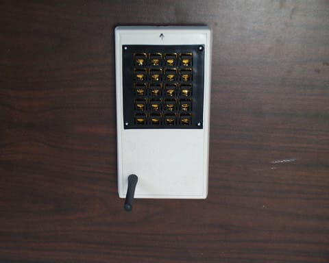
Click to zoom
Application Details
- Equipment Class
- DXX - Part 15 Low Power Communication Device Transmitter
- Date of Grant
- May 02, 2001
- Application Purpose
- Original Equipment
- Date of Application
- May 02, 2001
- Equipment Note
- Wireless Controller
- Frequency Range
- 902.00000000 - 928.00000000
- Company
- NEVCO Scoreboard Company
- Country
- United States
Documents & Files
Document Text
Text extracted from the exhibit documents filed with the FCC. Open a document above to read the original.
Users Manual
Scoreboard Operator’s Instructions MPCH Wireless Control Time Off Infrared Port Set Time On Time Off Next Poss. Home Team Fouls Guest Team Fouls Player Number 6 4 Dim 8 Player Fouls Weight Period Shift 1 5 2 9 3 0 7 Home Score Guest Score Blank On Direct Cable Horn T u r n d i s p l a y o f f S e t T i m e o f D a y Hold for 5 Seconds to: Bonus Some features on the keyboard overlay may not be included on the particular model being operated. Since 1934 Retain this manual in your permanent files 2-20-01 MPCH Basketball Instructions for: LED models: 2500-D 2500-A4-D 2540 2540-A4 2550-D 2560 9510 Introduction Welcome to the new MPCH wireless control now operating many of our current Nevco scoreboard model variations. It’s loaded with advanced operating features that will simplify and enhance the operation of your scoreboard system. Some of the features include: v Tenth second displayed on the scoreboard timer during the last minute of the game. v Set the Chronometer (time of day) on the scoreboard clock, it will keep accurate time even after turning off the control. v The control has the capability of direct cable connection in the event that your batteries are low. v The control has seven different channels or frequencies, each channel having a very large number of randomly selected Key Codes. This allows two different Nevco wireless controls to be on the same channel and yet not interfere with each other’s operation of their perspective scoreboard. Important Safety Information Save this manual. It contains important safety information and operating instructions. v Before using this product, please follow and adhere to all warnings, safety, and operating instructions located in this manual. v Do Not expose the product to water or moisture. v Do Not expose the product to extreme hot or cold temperatures. v Do Not expose the product to open flames. v Do Not allow objects to fall on, or liquids to spill on the product. v Do Not attempt to disassemble the product. Doing so will void the warranty. This product does not contain consumer-serviceable components. Service should be performed only by Nevco Service Department. v Do Not attempt to remove or replace the antenna. This antenna is permanently mounted internally. v Remove batteries when not in use for long periods of time (during off seasons). This will increase battery life and prevent battery corrosion. Always store this product in a cool and dry location when not in use. v Do Not plug this device into any other source other than its designed purpose. 1 234 6 7 The follow is a list of the terms used in this manual to describe your MPCH wireless control. 1Antenna 2Infrared Port 3On/Off Switch 4Direct Cable Connector 5LED Power Indicator 6Keyboard Overlay 7Battery Compartment Time Off Infrared Port Set Time On Time Off Next Poss. Home Team Fouls Guest Team Fouls Player Number 6 4 Dim 8 Player Fouls Weight Period Shift 1 5 2 9 3 0 7 Home Score Guest Score Blank On Direct Cable Horn T u r n d i s p l a y o f f S e t T i m e o f D a y Hold for 5 Seconds to: Bonus 5 Wireless Control Component Illustration Start Up Procedure Connecting the Receiver to the Scoreboard The receiver is connected to the scoreboard using a cable, which is provided, and plugged into a telephone jack located near the power input. The receiver receives its power from the scoreboard, therefore not requiring any batteries. The control requires 4 each AA batteries, which are not included. Once you have installed the batteries in the control and plugged the receiver into the scoreboard, follow the instructions below. Power must be turned on at the scoreboard before turning the wireless control on. Setting a random channel for operation The very first time that you use your wireless control, you must synchronize the control with the scoreboard that you are going to be operating by setting the channel. Once you have done this you will not have to do it again unless something would interfere with the signal. If this would happen, merely select another channel until the interference goes away. With the power turned on at the scoreboard, turn the wireless control on. The LED indicators on the receiver should flash for about five seconds. This indicates that you have power to the scoreboard and the control is transmitting a signal. The control is equipped with an infrared port, located on the front edge, as does the receiver. To set the control to a channel, hold the control within an inch of the receiver aligning the two infrared ports. The LED lights on the receiver will randomly flash for a few seconds indicating that the two infrared ports are communicating, as well as setting a channel. Once a channel is set, you cannot change to a different channel for at least 20 seconds. This feature eliminates accidental channel changing. Setting a Particular Channel for operation If you choose to select a particular channel, follow these simple steps: Select and hold down the key on the keyboard overlay of the channel number you desire (1 – 7). While holding down the key, align the infrared port on the control with the infrared port on the receiver. Continue holding the key down until the LED indicators on the receiver stop flashing, then release the key. The channel is now set. Below is a chart showing you which channel is being chosen when you see the LED indicators flashing on the receiver. The Signal LED will only flash while pressing a key on the control indicating that data is being sent and received. The Signal LED is the LED nearest the infrared port on the receiver. Channel 1òôôô ôòôô òòôô ôôòô òôòô ôòòô òòòô Channel 2 Channel 3 Channel 4 Channel 5 Channel 6 Channel 7 - L E D 1 - L E D 2 - L E D 4 - S i g n a l ò = LED On ô= LED Off Confirming your Channel Selection To confirm or determine which channel is set between the control and the receiver, try the following. Hold the TIME OFF key in the down position. You will notice that the Signal LED is flashing steadily. Now look at L…
Text truncated - open the document above for the full version.
Block Diagram
ROGERS LABS, INC.NEVCO SCOREBOARD COMPANY 4405 W. 259th TerraceMODEL: MPCH Transmitter Louisburg, KS 66053Test #: 010404FCCID#: PLH-ZW1 Phone/Fax: (913) 837-3214Test to: FCC Parts 2 and 15cPage 1 of 1 MPCHBlkDia.doc 05/01/2001 Block Diagram for MPCH
Cover Letter(s)
April 17, 2001 Timco Engineering Inc. 849 NW State Road 45 Newberry, FL 32669 Telephone 888.472.2424 Fax 352.472.2030 Applicant: NEVCO Scoreboard Company 301 East Harris Avenue Greenville, Illinois 62246 Telephone 618.664.0360 Fax 618.664.0367 Mary Gayle Nevinger President Equipment:FCC ID: PLH-ZW1 RE: Confidentiality for schematics Gentlemen: Lectrosonics Inc. requests that the material in the schematic diagrams be withheld from public disclosure in accordance with Section 0.459 of the Commissions Rules, 47 CFR 0.459, following the grant of certification. In support of this request, Lectrosonics Inc. submits the following: 1. Identification of the specific information for which confidential treatment is sought: The materials set forth in the schematic diagrams which are those for which confidentiality is sought. 2. Identification of the Commission proceeding in which the information was submitted or a description of the circumstances giving rise to the submission: The proceeding is that involving the application for equipment authorization (certification) under FCC ID number PLH-ZW1. 3. Explanation of the degree to which the information is commercial or financial, or contains trade secrete or is privileged: This material includes a detailed schematic of the device. As such this material is treated as highly confidential business information. 4. Explanation of the degree to which the information concerns a service that is subject to competition: The material for which confidentiality is ought is employed in the design and manufacture of wireless control systems transmitting equipment that is offered on a highly competitive basis. Customers for this equipment have a variety of competing sources. ROGERS LABS, INC. 4405 West 259 th Terrace Louisburg, KS 66053 Phone / Fax (913) 837-3214 l Page 2April 17, 2001 5. Explanation of how disclosure of this information could result in substantial competitive harm: Disclosure would, in effect, give away the fruits of the labors of the applicant’s engineering department and personnel, who have designed the equipment and manufacturing process. Disclosure would also offer competitors additional unwarranted insight into the state of the product development, thereby allowing competitors an advantage, not available to the applicant. 6. Identification of any measures taken by the submitting party to prevent unauthorized disclosure: The information for which confidential treatment is sought is kept confidential by the applicant and not made available to third parties except following non-disclosure agreements. 7. Identification of whether the information is available to the public and the extent of any previous disclosure of the information to third parties: To the knowledge of those preparing this application, the information has not been disclosed publicly heretofore. While the general theory of operation of this equipment has been the subject of numerous disclosures in industry and standards groups as well as in the rule making proceedings of the FCC, the protection sought is narrowly drawn and pertains to certain specific implementations of the digital circuitry technology. 8. Justification of the period during which the submitting party asserts that the material should not be available for public disclosure: This material should not be disclosed for at least 25 years. While improvements in the design are made relatively frequently, disclosure of the design information would lead to insights into both design and manufacturing techniques that could have an adverse competitive effect for many years to come. This equipment is designed for commercial, industrial and governmental applications. As such, unlike most consumer equipment, this equipment will be used for more than a decade in some cases. As such, it is important that the design not be made available to unauthorized persons who might attempt to use knowledge of the design to compromise the applications for which the equipment will be employed. 9. Any other information that the party seeking confidential treatment believes may be useful in assessing whether its request for confidentiality should be granted: See item 8 above. Note that the equipment for which approval is being sought will be employed in applications that inherently place a premium on security. The special fee for request of confidentiality will be submitted with the application. Should you require any further information, please contact the undersigned. Thank you for your consideration in this matter. Sincerely, Scot Rogers Rogers Labs, Inc. Enclosures
External Photos
ROGERS LABS, INC.NEVCO SCOREBOARD COMPANY 4405 W. 259th TerraceMODEL: MPCH Transmitter Louisburg, KS 66053Test #: 010404FCCID#: PLH-ZW1 Phone/Fax: (913) 837-3214Test to: FCC Parts 2 and 15cPage 1 of 2 MPCHTSup.doc 04/17/2001 External Photographs for MPCH ROGERS LABS, INC.NEVCO SCOREBOARD COMPANY 4405 W. 259th TerraceMODEL: MPCH Transmitter Louisburg, KS 66053Test #: 010404FCCID#: PLH-ZW1 Phone/Fax: (913) 837-3214Test to: FCC Parts 2 and 15cPage 2 of 2 MPCHTSup.doc 04/17/2001 FCC ID Label Location
ID Label/Location Info
935-XXXX MPCH ThisdevicecomplieswithPart15oftheFCCRules. Operationissubjecttothefollowingtwoconditions: (1)Thisdevicemaynotcauseharmfulinterference,and (2)Thisdevicemustacceptanyinterferencereceived, includinginterferencethatmaycauseundesired operation. NevcoScoreboardCompany Model:ZW-1 FCCID:PLH-ZW1 Canada:Pending
ID Label/Location Info
NVLAP Accredited LaboratoryNVLAP Lab Code: 200087-0 ROGERS LABS, INC.NEVCO SCOREBOARD COMPANY 4405 W. 259th TerraceMODEL: MPCH Transmitter Louisburg, KS 66053Test #: 010404FCCID#: PLH-ZW1 Phone/Fax: (913) 837-3214Test to: FCC Parts 2 and 15cPage 23 of 26 Certification\NEVCOMPCH.doc 04/17/2001 NEVCO SCOREBOARD COMPANY MODEL: MPCH WIRELESS CONTROLLER PHOTO FCC ID LABEL LOCATION and LABEL
Internal Photos
ROGERS LABS, INC.NEVCO SCOREBOARD COMPANY 4405 W. 259th TerraceMODEL: MPCH Transmitter Louisburg, KS 66053Test #: 010404FCCID#: PLH-ZW1 Phone/Fax: (913) 837-3214Test to: FCC Parts 2 and 15cPage 1 of 2 MPCHIntPho2.doc 05/01/2001 Internal Photographs for MPCH ROGERS LABS, INC.NEVCO SCOREBOARD COMPANY 4405 W. 259th TerraceMODEL: MPCH Transmitter Louisburg, KS 66053Test #: 010404FCCID#: PLH-ZW1 Phone/Fax: (913) 837-3214Test to: FCC Parts 2 and 15cPage 2 of 2 MPCHIntPho2.doc 05/01/2001
Test Report
ENGINEERING TEST REPORT FOR APLLICATION of GRANT of CERTIFICATION FOR CFR 47, PART 15C - INTENTIONAL RADIATORS Paragraph 15.249 For NEVCO SCOREBOARD COMPANY 301 East Harris Avenue Greenville, IL 62246 Mary Gayle Nevinger, President WIRELESS CONTROLLER Model: MPCH Wireless Control Frequency 902-928 MHz FCC ID#: PLH-ZW1 Test Date:April 4, 2001 Certification Date:April 4, 2001 Certifying Engineer: Scot D. Rogers ROGERS LABS, INC. 4405 West 259 th Terrace Louisburg, KS 66053 Phone: (913) 837-3214 FAX: (913) 837-3214 This report shall not be reproduced except in full, without the written approval of the laboratory. This report must not be used by the client to claim product endorsement by NVLAP or any agency of the U.S. Government. ROGERS LABS, INC. 4405 West 259 th Terrace Louisburg, KS 66053 Phone / Fax (913) 837-3214 NVLAP Accredited LaboratoryNVLAP Lab Code: 200087-0 ROGERS LABS, INC.NEVCO SCOREBOARD COMPANY 4405 W. 259th TerraceMODEL: MPCH Transmitter Louisburg, KS 66053Test #: 010404FCCID#: PLH-ZW1 Phone/Fax: (913) 837-3214Test to: FCC Parts 2 and 15cPage 2 of 26 Certification\NEVCOMPCH.doc 04/17/2001 TABLE OF CONTENTS FORWARD:.....................................................................................................................3 1)APPLICABLE STANDARDS & TEST PROCEDURES.............................................3 2.1033(b)Application for Certification..............................................................................................................4 2)EQUIPMENT TESTED...............................................................................................5 3)EQUIPMENT FUNCTION AND TESTING PROCEDURES.......................................5 4)EQUIPMENT AND CABLE CONFIGURATIONS......................................................5 Conducted Emission Test Procedure.................................................................................................................5 Radiated Emission Test Procedure:...................................................................................................................5 5)LIST OF TEST EQUIPMENT.....................................................................................6 6)UNITS OF MEASUREMENTS...................................................................................7 7)TEST SITE LOCATIONS...........................................................................................7 8)SUBPART B – UNINTENTIONAL RADIATORS.......................................................7 Conducted EMI...................................................................................................................................................7 Radiated EMI......................................................................................................................................................8 Data: General Radiated Emissions from EUT (6 Highest Emissions).............................................................10 Summary of Results for Conducted Emissions...............................................................................................10 Summary of Results for Radiated Emissions..................................................................................................11 Statement of Modifications...............................................................................................................................11 9)SUBPART C - INTENTIONAL RADIATORS...........................................................11 15.203 Antenna Requirements..........................................................................................................................11 15.205 Restricted Bands of Operation.............................................................................................................11 Data: Emissions in Restricted Bands................................................................................................................12 Summary of Results for Radiated Emissions in Restricted Bands:...............................................................12 15.209 Radiated Emissions Limits; General Requirements...........................................................................13 Radiated EMI....................................................................................................................................................13 Data: General Radiated Emissions from EUT (6 Highest Emissions).............................................................14 Summary of Results for Radiated Emissions:.................................................................................................14 15.249 Operation in the Band 902-928 MHz...................................................................................................14 Data: Radiated Emissions from EUT................................................................................................................16 Summary of Results for Radiated Emissions of Intentional Radiator..........................................................17 Statement of Modifications...............................................................................................................................17 APPENDIX....................................................................................................................18 NVLAP Accredited LaboratoryNVLAP Lab Code: 200087-0 ROGERS LABS, INC.NEVCO SCOREBOARD COMPANY 4405 W. 259th TerraceMODEL: MPCH Transmitter Louisburg, KS 66053Test #: 010404FCCID#: PLH-ZW1 Phone/Fax: (913) 837-3214Test to: FCC Parts 2 and 15cPage 3 of 26 Certification\NEVCOMPCH.doc 04/17/2001 FORWARD: The following is submitted for consideration in obtaining a Grant of Certification for low power intentional radiators per CFR Paragraph 15.249. Name of Applicant: NEVCO SCOREBOARD COMPANY 301 East Harris Avenue Greenville, IL 62246 Models: MPCH Wireless Control FCC I.D.:PLH-ZW1 Frequency Range: 902-928 MHz Operating Power: Less than 50 mV/m @ 3 Met…
Text truncated - open the document above for the full version.
Test Setup Photos
ROGERS LABS, INC.NEVCO SCOREBOARD COMPANY 4405 W. 259th TerraceMODEL: MPCH Transmitter Louisburg, KS 66053Test #: 010404FCCID#: PLH-ZW1 Phone/Fax: (913) 837-3214Test to: FCC Parts 2 and 15cPage 1 of 1 MPCHTSup.doc 04/17/2001 Test Set-up Photographs for MPCH
Contact Information
Applicant
Gayla Moore(President)
Test Firm
Rogers Labs, Inc.Scot Rogers
Technical Specifications
| # | Rule Parts | Frequency Range | Power Output |
|---|---|---|---|
| 1 | 15C | 902 MHz - 928 MHz | - |
Other Applications from NEVCO Scoreboard Company

PLH-USC
Aug 21, 2005WIRELESS CONTROLLER FOR PORTABLE SCOREBOARD
Equipment Class
DXX - Part 15 Low Power Communication Device Transmitter
PLH-ZW4
Jul 01, 2004LOW POWER TRANSMITTER
Equipment Class
DXX - Part 15 Low Power Communication Device Transmitter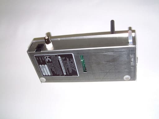
PLH-ZW3
May 30, 2002Spread Spectrum Device
Equipment Class
DSS - Part 15 Spread Spectrum Transmitter
PLH-ZW2
May 30, 2002Spread Spectrum Transmitter
Equipment Class
DSS - Part 15 Spread Spectrum Transmitter