PLS-ES500-A-RFTRFT Listener
Excel Energy Technologies, Ltd.
Click to zoom
Application Details
- Equipment Class
- DXT - Part 15 Low Power Transceiver, Rx Verified
- Date of Grant
- Sep 16, 2001
- Application Purpose
- Original Equipment
- Date of Application
- Sep 16, 2001
- Equipment Note
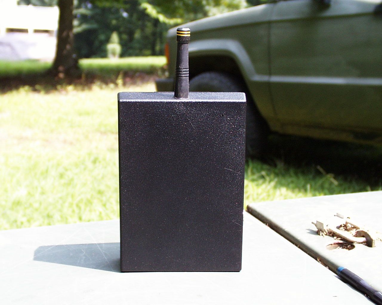
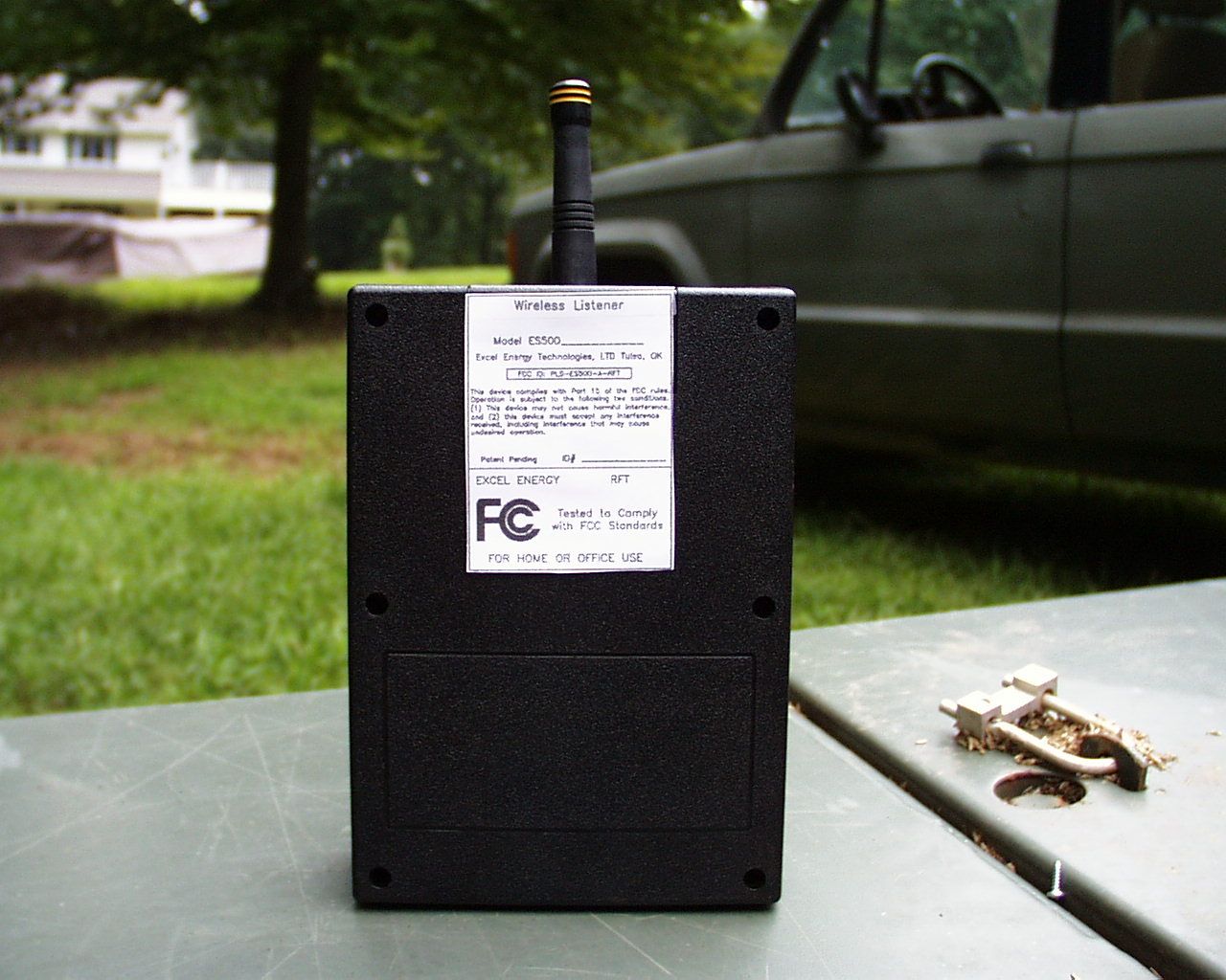
- RFT Listener
- Frequency Range
- 916.20000000 - 916.80000000
- Country
- United States
Documents & Files
Document Text
Text extracted from the exhibit documents filed with the FCC. Open a document above to read the original.
Users Manual
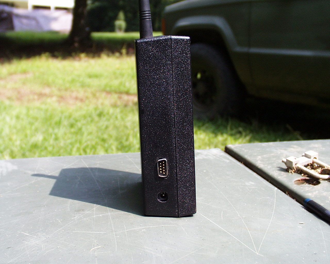
Owners Manual DRAFT The wireless - internet enabled data collection system ES100 TEMPERATURE SENSOR ES200 PULSE TOTALIZER ES300 REPEATER ES500 LISTENER Please Read Before Using This Equipment Congratulations You are now the owner of the ExcelSyus TM "Listener", a wireless, internet enabled data collection system. With this system you have the flexibility of various modes of communication to receive the information back to the Excel Web Servers for publishing on your browser. The complete ExcelSyus TM "Listener" utilizes a radio signals to communicate between wireless sensor's which transmit Celsius and Fahrenheit temperature readings. Also the wireless data totalizer which transmit total counts of items such as energy usage, operation cycles, and Battery powered wireless sensor has a small green LED to notify of active data transmission. A small push button switch is barely visible for transmit activation in addition to the normal transmission schedules. Battery All the devices contained in the complete ExcelSyus TM "Listener" products include battery operation. The transmitters require battery operation but the ExcelSyus TM "Listener" and repeater uses an optional battery for power loss requirements. The normal battery life for the wireless sensor and wireless totalizer are greater than 18 months. The normal transmission of the data for both of these devices include an alert for low battery power and can be observed on the internet web site. System The ExcelSyus TM "Listener" system includes several components - "Listener" software, "Listener" device, repeater, wireless sensors, and wireless data totalizer. The ExcelSyus TM "Listener" can be connected to several different devices including a standard PC running on a Microsoft Windows operating system, a modem connection, or an ExcelSyus TM "Monitor" system. Operation The operation of the ExcelSyus TM "Listener" system is subdivided into the five system components: A. "Listener" Software The "Listener" Software is designed to run using Microsoft's Internet Explorer version 5.0 or greater. Through Internet "SMTP" technology data is transferred to Excel's Internet Web Server. To ensure proper operation select from Microsoft Internet Explorer tools/Internet options/programs/e-mail and choose whichever email application the PC uses. The "Listener" software will use this conduit to transfer the data packets to Excel Energy Technologies. Install the "Listener" software into a folder. The application is very small and no entrys are made into your computer system registry. One the installation is made the PC is ready to activate the ExcelSyus TM "Listener" system. B. ExcelSyus TM "Listener" The "Listener" has two communication ports. One uses RS-232 and the other is RS-485. The PC attachment normally uses RS-232 however with a RS-485 card installed in your PC you can also use RS-485 and daisy chain the "Listeners." Through use of a null modem cable attach the ExcelSyus TM "Listener" to the PC Com port. When connecting the Listener to the ExcelSyus Building Control Panel, use a null modem to the RS-485 ports on both devices. C. Repeater The repeater is used to boost the signals coming from the wireless transmitters. They are simply installed in locations that allow the radio signals to go around dense metal areas or to increase the distance between the wireless transmitting devices and the "Listener." There is no setup required since the built-in intelligence recognizes Excel communication and simply rebroadcasts that data. D. Wireless Sensor Operation of the wireless sensor is very simple and requires very little detail for proper operation. The main concern for the proper operation centers around getting the transmitted radio signals to the ExcelSyus TM "Listener." Items to avoid in order to improve the performance include staying away from dense wall structures or metal objects. Distance between the "Listener" and wireless sensors should be no more than 700 feet for good reception. If increased range is desired simply use the ExcelSyus TM "Repeater." Other items to bear in mind while placing the wireless sensor are to avoid areas above hot surfaces such as cook tops, ovens, lights, sunlight heated objects, etc. E. Wireless Data Totalizer The wireless data totalizer is similar to the operation of the wireless sensor except for the addition of the pulse input. The wireless data totalizer is constructed for sealed weather tight operation. For this reason the operation is activated by joining the two "enabling" control wires. The two input wires must be attached to the pulse initiation device that allows a low voltage signal to energize/de-energize. Again, the main concern for the proper operation of the wireless data totalizer centers around getting the transmitted radio signals to the ExcelSyus TM "Listener." Items to avoid in order to improve the performance include staying away from dense wall structures and/or metal objects. Distance between the "Listener" and wireless data totalizer should be no more than 700 feet for good reception. If increased range is desired simply use the ExcelSyus TM "Repeater." Optimization The Federal Communications Commission (FCC) places power limits upon devices that transmit as intentional radiators. This power limitation directly affects the distance or receiving range of the ExcelSyus TM "Listener" system. The main concern for the proper operation centers around getting the transmitted radio signals to the ExcelSyus TM "Listener." Items to avoid in order to improve the performance include staying away from dense wall structures or metal objects. Distance between the "Listener" and wireless sensors should be no more than 700 feet for good reception. If increased range is desired simply use the ExcelSyus TM "Repeater." The broadcast range of the ExcelSyus TM "Listener" may be limited by a number of external factors listed above. Therefore, the following suggestions may be helpful in getting the optimal range. 1.…
Text truncated - open the document above for the full version.
Block Diagram
DB9 ANTENNA BLOCK DIAGRAM EXCEL ENERGY TECHNOLOGIES, LTD. 11 ES500/ES300 RF BOARD LOGIC BOARD BACKUPBATTERY 10 VOLTS POWER SUPPLY/CHARGER 5 VOLTS RS-232/485 INTERFACE 5 VOLTS 3 VOLTS + REG MICRO- MEMORY PROCESSOR CONTROLLER MICRO- RF CHIP TR1000L INPUT 24 VAC { 12 VDC AB CD 4 321 D C B A 12 34 of SheetDrawn by Rev Number TitleSize A DateFilename
Operational Description
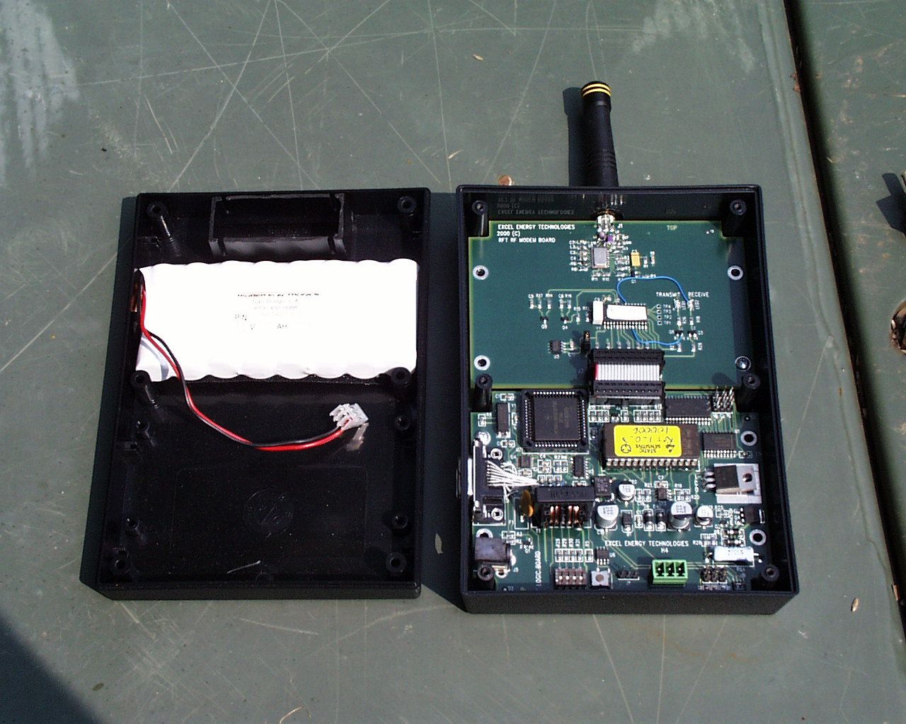
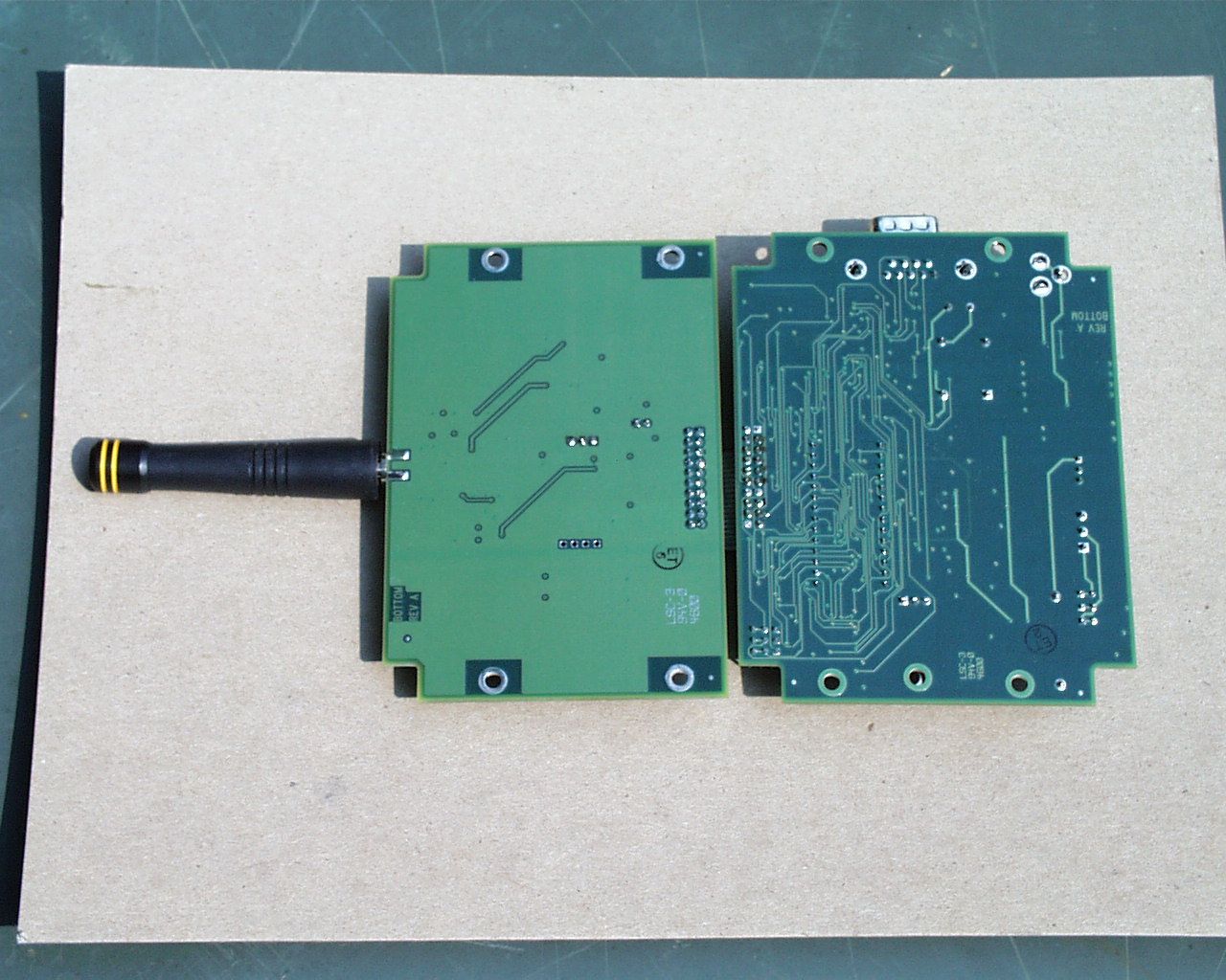
624 S. Boston, Suite 300 Last modified 3/1/2001 Tulsa, Oklahoma 74119 (918) 585-5000 Fax (918) 585-5002 1 Circuit Description for ExcelSyus products LOGIC BOARD Sheet 1 of 3 This sheet shows the microprocessor and memory. The SRAM is 32K x 8 and the EPROM is also 32K x 8. Also shown on this sheet is 128K x 8 FLASH memory. The board is set up to use either the EPROM or the FLASH. Sheet 2 of 3 This sheet shows the RS485 circuit driver and the RS232 UART circuit driver. Sheet 3 of 3 This is the power supply and SPI expansion interface drawing. The power supply is designed for 12VDC input or 24VAC input. This section also has battery backup circuitry. The SPI expansion port will allow for future expansion and interfaces directly to the RF Modem board. These two boards are included in the same enclosure and together they make up the product. The trade name for this product is called “ExcelSyus Listener”. RF MODEM BOARD Sheet 1 of 2 This sheet shows the microcontroller circuitry that interfaces to the RF Transceiver circuit and the SPI expansion port. This section includes a receive LED and a transmit LED that is useful for troubleshooting and system diagnostics. A 4-pole dipswitch is included that, when set, will cause 3 data packets to be transmitted on every transmission. The default is to transmit a single data packet on every transmission. Another pole on the dipswitch is used to configure the unit as a repeater. If set, the RF modem will continue to receive data packets as before, but will repeat the signal if the repeat setting in the data packet has not been set. It will not repeat a repeated data packet. If it is not set as a repeater, the received data packet is pass on to the logic board through the SPI expansion port. The other two poles of the dipswitch are available for future use. Sheet 2 of 2 This sheet shows the RFM transceiver and antenna interface. 624 S. Boston, Suite 300 Last modified 3/1/2001 Tulsa, Oklahoma 74119 (918) 585-5000 Fax (918) 585-5002 2 PULSE TOTALIZER BOARD Sheet 1 of 1 This sheet shows the battery input (11.0VDC to 3.6VDC) and a low-dropout regulator that will also detect a low battery condition. On the drawing is the pulse input. The expected pulse input is a relay contact closure. Every pulse transmission will wake-up the microcontroller and will be counted. U2 is the RF transmitter and a trace on the board provides the antenna. A low-power one-minute WDT (watchdog timer) is also included to wake up the microcontroller. This will allow the Pulse Totalizer to use very little power since it will be in low-power mode most of the time. The Totalizer will transmit at a selectable 3 or 5 minute interval. A transmit enable circuit is on the board to only allow transmissions when in service. The unit is designed to be factory sealed to prevent moisture and weather related problems. The unit is shipped with the transmitter disabled. Connecting the two transmit enable wires will enable the transmitter. TEMPERATURE SENSOR BOARD Sheet 1 of 1 This sheet shows the battery input (11.0VDC to 3.6VDC) and a low-dropout regulator that will also detect a low battery condition. The circuit includes a push button switch that is used for testing and for putting the zone in override. A connector is provided on the board to allow connection to a precision thermistor. U2 is the RF transmitter and a trace on the board provides the antenna. A low-power one-minute WDT (watchdog timer) is also included to wake up the microcontroller. This will allow the Temperature Sensor to use very little power since it will be in low-power mode most of the time. The Temperature Sensor will transmit once every 5 minutes or once every minute if the temperature change is greater than one degree F. The Led is used to indicate when a transmission has occurred. EXCELSYUS ‘M’ BOARD Sheet 1 of 11 This sheet shows the microprocessor and memory. It also includes a RTC (Real Time Clock). Sheet 2 of 11 This is the power supply section. It detects power outages and will automatically convert to battery power. A battery charging circuit is also included. Sheet 3 of 11 This is the A/D converter section. It converts the temperature sensors current input to a digital value. The A/D section has a Gain and Span pot that is factory calibrated. 624 S. Boston, Suite 300 Last modified 3/1/2001 Tulsa, Oklahoma 74119 (918) 585-5000 Fax (918) 585-5002 3 Sheet 4 of 11 This sheet contains the Keyboard and Display interface. Sheet 5 of 11 This sheet contains the scanning LED’s and 4-pole dipswitch. The dipswitch is used to select Telephone modem settings. Sheet 6 of 11 This sheet contains the RS232 port, the RS484 port and a power-out indicator latch. Sheet 7 of 11 This sheet contains the I/O ports for turning on/off the external Triacs. Sheet 8 of 11 This sheet contains the Pulse meter input section and the external Thermocouple interface section. Sheet 9 of 11 This sheet is left intentionally blank. Sheet 10 of 11 This is the Analog input filter section. Sheet 11 of 11 This sheet is left intentionally blank. KEYPAD & DISPLAY BOARD Sheet 1 of 1 This sheet contains the external keypad and a 7-digit display. THERMOCOUPLE BOARD Sheet 1 of 2 This sheet contains the 12-bit A/D Converter and interface to the ExcelSyus. The board will allow up to 14 external J-Type thermocouples. Sheet 2 of 2 This sheet contains the power supply section. The main function of this circuit is to convert positive 5V to negative 5V. It uses a voltage doubler, an inverter, and a negative voltage regulator to achieve this task.
Test Report
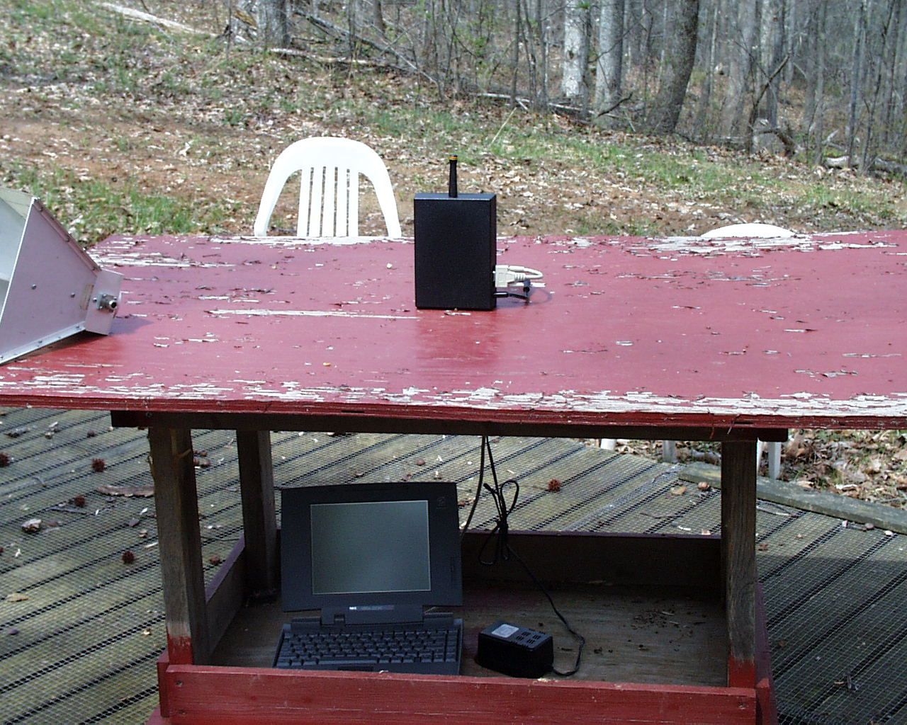
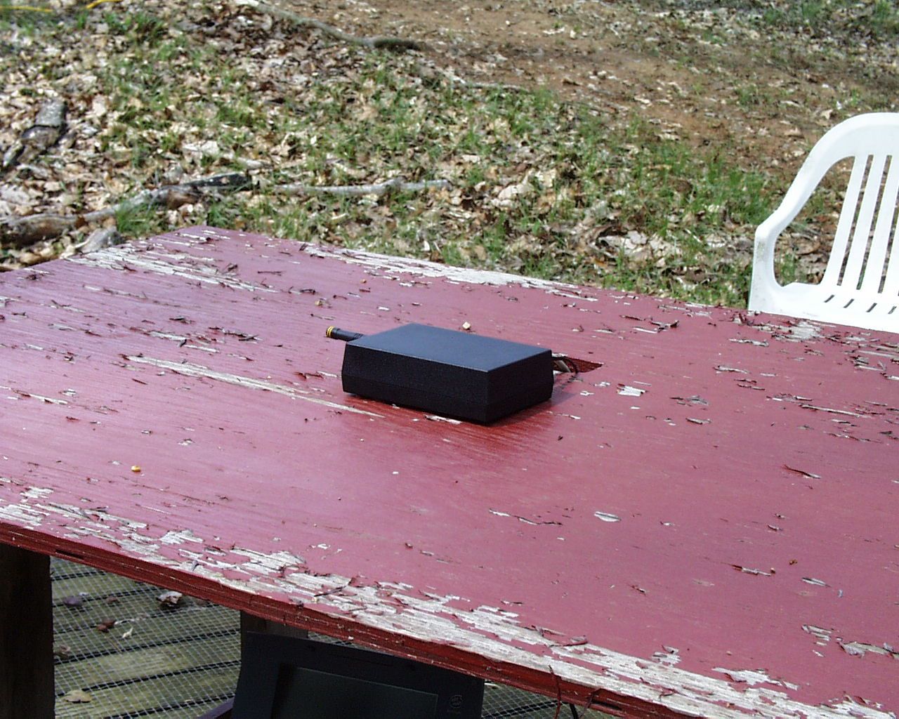
PLS-ES500-A-RFT 1 Test Report DUT:Wireless temperature sensor model ES500-A-RFT Test Date:13-July-2001 Manufacturer:Excel Energy Technologies, Ltd. 624 S. Boston, Suite 300 Tulsa, OK 74119 (918) 585-5000 Conducted by:Control Design & Testing, Inc. 6010 Red Fox Drive Spotsylvania, VA 22553 (540) 582-2826 PLS-ES500-A-RFT 2 CD&T FCC ID: PLS-ES500-A-RFT A. DEVICE UNDER TEST The product, designated the RFT, is a transceiver used to collect and relay data as part of an energy management system. The product is designed to operate under the provisions of Part 15.249 of the FCC rules and has been issued a Declaration of Conformity by Timco Engineering, Inc. This device receives data from two transmitters, the PLS-ES100-A-TS temperature sensor and the PLS-ES200-A-PT pulse totalizer. The data received is then relayed to a computer or an Excelsyus (host system) main unit through an RS-485/232 port. This device can also be programmed to operate as a stand alone data collection point and retransmit the received data on to another RFT for remote downloading. When programmed as a receiving terminal for connection to a host system the device is referred to as a “listener” and designated ES500. When setup as a stand alone device it is referred to as a “repeater” and designated ES300. The circuitry is identical for both configurations and will be labeled PLS-ES500-A-RFT in either case. The transmit frequency is 916.500 MHz. nominal. The modulation mode is on/off keying using a pulse width scheme. The device is powered from an external source of either 12VDC or 24VAC and has an internal 9.6 volt NiCad backup battery . The tranceiver circuitry is regulated at 3 volts. The rf section consists of an RF Monolithics TR1000L transceiver module, a two element antenna matching network and molded rubber ¼ wave antenna. The antenna has a reverse pinned SMA connector molded into the base and connects to a matching threaded connector mounted on the circuit board. B. MEASUREMENT PROCEDURE: RADIATED EMISSIONS Testing of this device was conducted at the Hyak Laboratory test facility located in Spotsylvania, Virginia. Transmitter field strength measurements were conducted according to the procedures set forth in ANSI C63.4 (1992). Testing was conducted with power supplied from a 12 volt class 2 power transformer with back-up batteries installed. The RS-232 data port was connect to COM1 on an NEC 2205C notebook computer. The compter was programmed to control the transmit and receive functions. The device under test was placed on a rotating turntable 0.8 meters high, centered at 3 meters distant from the measurement antenna. The device was placed in the center of PLS-ES500-A-RFT 3 the turntable with the computer placed underneath on a lower shelf. The device was tested in two positions shown in the test setup photographs. For the purpose of testing, the sample was made to transmit a continuous 1 kHz, 50% duty cycle pulse stream. However, the occupied bandwidth (Plot 1) was captured with the sample device transmitting typical data packets. Plot 1 The field strength measurements were taken using an HP8596E spectrum analyzer, an EMCO 3121C dipole set, an EMCO 3115 double ridge guide horn and an Avantek UJ210 preamp. The device was scanned in both transmit and receive modes from 30MHz. to 10GHz. and all emissions were noted. In this case, the only emissions detected were those harmonically related to the fundamental transmit frequency. The receiver in this device is a pulse sequenced TRF clocked at 725 kHz. nominal and has no local oscillator. An effort was made to detect emissions that would be PLS-ES500-A-RFT 4 harmonically related to the sequencer clock but none were found. At each detected emission frequency, the device was measured by rotating the turntable and adjusting the antenna height over a range of 1 to 4 meters to obtain the maximum output level. This procedure was performed with both horizontal and vertical antenna polarizations for both of the setup positions shown in the test setup photos. The peak reading for each frequency was recorded in the fourth column in Table 1 below. Measurements taken for weak emissions were performed by reducing the distance from the measurement antenna to 1 meter and factoring –9.54dB into the calculation. This method was used for the 6 th and 7 th harmonics. C. DUTY CYCLE AND INTERVAL CALCULATIONS The occupied bandwidth measurement was made using an HP8596E spectrum analyzer and plotted with an HP7475A pen plotter. The duty cycle correction factor for this device is approximately –6dB, but since the peak readings for all detected harmonics were below the limits, the duty cycle correction factor was not applied to the calculations. CLIENT: EXCEL ENERGYFCC ID: PLS-ES500-A-RFT EUT: DATA TRANSMITTER PART 15.249, 15.35TEST DATE: 13-JULY-01 Ant. Polar. H/V 916.470V30.5-43.650.0492614926150000 1832.940V30.2-89.850.0233233500 2749.410V33.4-96.080.0164164500 3665.880H35.7-98.310.0166166500 4582.349H36.6-102.610.0112112500 5498.819V38.6-109.440.06464500 6415.288H39.1-114.250.03939500 Table 1 RADIATED EMISSIONS DATA Frequency In MHz. Peak Power uV/m@3m Peak reading dBm Ant. Factor dB ANTENNA: DIPOLES/DRG HORN Duty Cycle -dB FCC Limit uV/m@3m Corrected Power uV/m@3m
Contact Information
Applicant
Philip L Parsons(Director, R&D)
Test Firm
Hyak Laboratories, Inc.Rowland Johnson
703-451-1188
Technical Specifications
| # | Rule Parts | Frequency Range | Power Output |
|---|---|---|---|
| 1 | 15C | 916.2 MHz - 916.8 MHz | - |
Other Applications from Excel Energy Technologies, Ltd.

PLS-ES100-A-TS
Sep 16, 2001Temperature Sensor
Equipment Class
DXX - Part 15 Low Power Communication Device Transmitter
PLS-ES200-A-PT
Sep 16, 2001Pulse Totalizer
Equipment Class
DXX - Part 15 Low Power Communication Device Transmitter