PMM046480565Low Power Golf Club Reminder
Tasco Products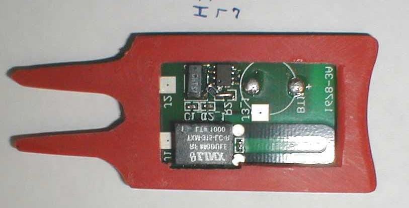
Click to zoom
Application Details
- Equipment Class
- DSC - Part 15 Security/Remote Control Transmitter
- Date of Grant
- Jul 05, 2001
- Application Purpose
- Original Equipment
- Date of Application
- Jul 05, 2001
- Equipment Note
- Low Power Golf Club Reminder
- Frequency Range
- 314.00000000 - 315.00000000
- Company
- Tasco Products
- Country
- United States
Documents & Files

Document Text
Text extracted from the exhibit documents filed with the FCC. Open a document above to read the original.
Users Manual
Club-Minder - User’s Guide Club-Minder is the first useful electronic device designed to help prevent golfers from losing or temporarily misplacing their clubs during play. It is a simple device incorporating a familiar and regularly used golf accessory, the divot tool, which doubles as a club rest to keep club grips dry and clean, particularly when putting and chipping around the greens. The divot tool/club rest incorporates an encapsulated transmitter and rechargeable battery. When in use, the club rest sends an electronic code to a receiver, which is a pager size device worn by the golfer with the aid of a belt clip. Should the golfer leave the area where a club has been placed on or near the club rest, the receiver automatically warns the user through a series of audible sounds or “beeps” before the user has left the area. Not only is loss of a club prevented, but slowing down play to retrieve a club left at a previous hole is eliminated because Club-Minder warns the user of a forgotten club before the user gets approximately 50-75 yards away from that club. The simple act of using the club rest/divot tool for another of its many intended functions saves time, money and embarrassment. Instead of having to ask the foursome behind you if they found your $100 sand wedge, Club-Minder will remind you to pick up your club before you even get to the next tee. The Club-Minder receiver includes two “AAA” batteries. These are replaceable when discharged and are used to charge the rechargeable battery that is housed in the club rest. The method of recharging is also a simple process that automatically occurs when the device is stored in the golf bag between rounds. By properly inserting the club rest into the belt clip between rounds, the receiver’s batteries automatically charge the rechargeable battery, which charge is designed to last up to six hours, more than enough time to complete a normal round of golf. Should the club rest ever be misplaced or lost, replacements are available from TASCO Products. By attaching a new club rest to the receiver for initial charging of the transmitter battery, the receiver will “teach” the transmitter what code to send from hundreds of random codes determined by the receiver. This way there is rarely a likelihood of interference from another nearby Club-Minder user. And you never have to worry that misplacing the club rest would render Club-Minder unusable. Note: The receiver has several external metal contacts used for charging the transmitter’s rechargeable battery. To prevent an internal short, do not store or carry the receiver with coins, keys or any other electrically conductive materials that might inadvertently create a complete electrical circuit between the external contact points used to recharge the transmitter. FCC Communications Radio Frequency Interference Statement Tasco Products CM67 Tested to comply with FCC standards FOR OUTDOOR USE ONLY FCC CClluubb--MMiinnddeerr IInnssttrruuccttiioonnss..ddoocc Warning: Changes or modifications to this unit not expressly approved by the party responsible for compliance could void the user’s authority to operate this equipment. This device complies with Part 15 of the FCC Rules. Operation is subject to the following conditions: (1) this device may not cause harmful interference, and (2) this device must accept any interference received, including interference that may cause undesired operation.
Cover Letter(s)
May 2, 2001 American Telecommunications Certification Body, Inc. 6731 Whittier Avenue Suite C110 McLean, VA 22101 To Whom It May Concern: Please be advised that Tasco Products authorizes Washington Labs to act on our behalf, until otherwise notified, for applications submitted to American Telecommunications Certification Body, Inc. (ATCB). We certify that we are not subject to denial of federal benefits, that includes FCC benefits, pursuant to Section 5301 of the Anti-Drug Abuse ACT of 1988, U.S.C. 862. Further, no party, as defined in 47 CFR 1.2002(b), to the application is subject to denial of federal benefits, that includes FCC benefits. Thank you for your attention to this matter. Robert A. Jackson Chief Executive Officer Tasco Products RAJ:csm TASCO Products 9710 Farrar Court, Suite O Richmond, Virginia 23236 804-323-0275 www.club-minder.com
Cover Letter(s)
May 2, 2001 American Telecommunications Certification Body, Inc. 6731 Whittier Avenue Suite C110 McLean, VA 22101 RE: Certification Application FCC ID: PMM8046480565 Please be advised that the following exhibits are be held confidential on behalf of Tasco Products: • Schematic diagrams The application contains technical information that Tasco Products deems to be trade secrets and proprietary. If made public, the information might be used to the disadvantage of the applicant in the market place. Thank you for your attention to this matter. Robert A. Jackson Chief Executive Officer Tasco Products RAJ:csm TASCO Products 9710 Farrar Court, Suite O Richmond, Virginia 23236 804-323-0275 www.club-minder.com
Cover Letter(s)
May 2, 2001 American Telecommunications Certification Body, Inc. 6731 Whittier Avenue Suite C110 McLean, VA 22101 RE: Certification Application FCC ID: PMM8046480565 To Whom It May Concern: Please be advised that the manufacturer will ensure that the above-referenced model will be manufactured in accordance with the FCC Rules and Regulations. Thank you for your attention to this matter. Robert A. Jackson Chief Executive Officer RAJ:csm TASCO Products 9710 Farrar Court, Suite O Richmond, Virginia 23236 804-323-0275 www.club-minder.com
External Photos
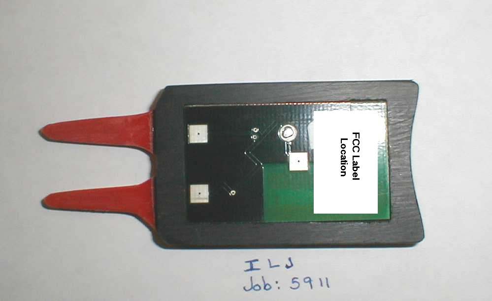
PCB Front PCB Back
Internal Photos
PCB Front PCB Back
Operational Description
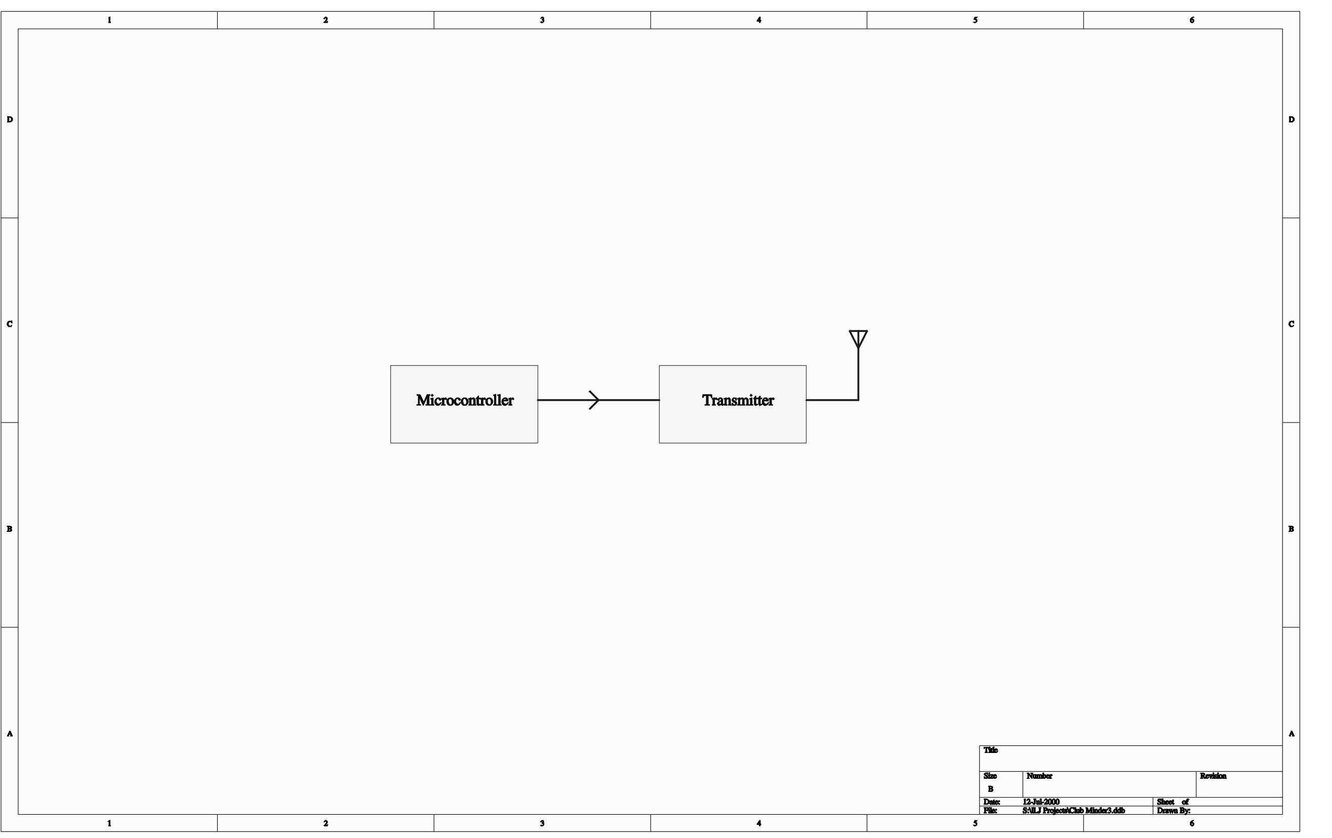
ILJ Club Minder Operation The system must do the following: The system has two components. They are the transmitter and the receiver. The transmitter is powered by a rechargeable battery which is charged by the dry cells in the receiver. The system has three modes of operation. One occurs during the time that the two units are joined together. The other two occur during the time that the two units are apart. At the moment in time that the two units are joined, the receiver captures the 8 bit value from its real time clock and stores it as its random ID Code. It then attempts to transmit that code to the transmitter and receive the proper confirmation. It beeps once to signify proper connection. During the time that two units are joined, the receiver periodically transmits the ID Code to the the intercom line and receives confirmation from the transmitter, thus confirming the connection. Each unit powers down its RF system and consumes minimum power. The transmitter battery is charged from the receiver battery. Right after the two units are separated, the transmitter waits one intercom pulse interval and then executes its first transmission to the receiver. The receiver looks for the transmission, and upon receiving it, beeps twice to signify proper operation. During the time that the two units are separated, the transmitter must transmit its code every 10 seconds. It must not have a duty ratio greater than 1/30. The receiver is powered shortly before each anticipated reception. When a reception succeeds, the receiver's LED quickly flashes twice to provide reassurance of proper operation. If the reception fails, the receiver is left on until a reception occurs or two successive transmissions are missed, at which point the buzzer chirps once and LED light flashes repeatedly. After 10 more seconds of failure, the buzzer chirps more vehemently. If radio connection is not reestablished after 60 seconds, the receiver is turned off to conserve battery power and the unit enters a mode waiting for intercom connection. During the time that the two units are separated, the receiver periodically attempts to communicate with the transmitter via the intercom connection. The transmitter watches for intercom communication any time that it is not transmitting RF. Immediately after reset, the transmitter looks for 10 seconds for the receiver intercom signal. If the intercom signal is not found, then the transmitter assumes that it has been inadvertently reset and begins transmitting. If the transmitter does not have a valid copy of the identification code, then it does not transmit RF and looks continuously for the receiver intercom signal. Immediately after reset, the receiver attempts to signal the transmitter over the intercom. If that fails then it verifies that has a valid copy of the identification code and then looks for the transmitter RF signal as if it has just missed an anticipated reception. If it does not have a valid copy of the identification code then it alarms until the maximum alarm time is exceeded and then enters a low power mode waiting for an intercom connection.
Test Report
FCC CERTIFICATION TEST REPORT for Tasco Products 9710 Farrar Court, Suite O Richmond, VA 23236 FCC ID: PMM8046480565 May 2, 2001 WLL PROJECT #: 5911X This report may not be reproduced, except in full, without the prior written consent of Washington Laboratories, Ltd. ILJ Corporation FCC ID:PMM8046480565 WLL Project #:5911X i TABLE OF CONTENTS 1.0 INTRODUCTION...........................................................................................................................................................1 1.1 SUMMARY......................................................................................................................................................................1 2.0 DESCRIPTION OF EQUIPMENT UNDER TEST (EUT).................................................................1 2.1 ON-BOARD OSCILLATORS...........................................................................................................................................1 3.0 TEST CONFIGURATION............................................................................................................................................2 3.1 CONDUCTED EMISSIONS TESTING...........................................................................................................................2 3.2 RADIATED EMISSIONS TESTING...............................................................................................................................2 3.3.1 Radiated Data Reduction and Reporting............................................................................2 Tables Table 1. Conducted Emissions Results Table 2. Radiated Emissions Results Table 3. System Under Test Table 4. Interface Cables Used Table 5. Measurement Equipment Used Appendices Appendix A. Statement of Measurement Uncertainty ILJ Corporation FCC ID:PMM8046480565 WLL Project #:5911X 1 FCC CERTIFICATION TEST REPORT for Tasco Products FCC ID: PMM8046480565 1.0 Introduction This report has been prepared on behalf of ILJ Corporation to support the attached Application for Equipment Authorization. The test and application are submitted for a Periodic Intentional Radiator under Part 15.231 of the FCC Rules and Regulations. The Equipment Under Test was the CM-67 Club Minder. All measurements herein were performed according to the 1992 version of ANSI C63.4. The measurement equipment conforms to ANSI C63.2 Specifications for Electromagnetic Noise and field Strength Instrumentation. Calibration checks are made periodically to verify proper performance of the measuring instrumentation. All measurements are performed at Washington Laboratories, Ltd. test center in Gaithersburg, MD. Site description and site attenuation data have been placed on file with the FCC's Sampling and Measurements Branch at the FCC laboratory in Columbia, MD. Washington Laboratories, Ltd. has been accepted by the FCC and approved by NIST NVLAP (NVLAP Lab Code: 200066-0) as an independent FCC test laboratory. All results reported herein relate only to the equipment tested. The measurement uncertainty of the data contained herein is ±2.3 dB. Refer to Appendix A for Statement of Measurement Uncertainty. This report shall not be used to claim product endorsement by NVLAP or any agency of the US Government. 1.1 Summary The ILJ Corporation CM-67 Club Minder complies with the limits for a Periodic Intentional Radiator under Part 15.231(e) of the FCC Rules and Regulations. 2.0 Description of Equipment Under Test (EUT) The ILJ Corporation Club-Minder CM67 (EUT) is a device that is designed to prevent golfers from losing their clubs or leaving them behind when moving from one playing hole to another. The EUT a low power intentional radiator used in conjunction with a receiver. The receiver is clipped to the belt of a golfer. The transmitter is contained within a divot repair tool that a golf club handle rests upon. The transmitter transmits for a duration of 0.3 seconds every 10 seconds and if the belt clip receiver travels out of range of the signal an alarm is sounded. 2.1 On-board Oscillators The ILJ Corporation CM-67 Club Minder contains the following oscillators: 32.768kHz, 315MHz SAW Oscillator. ILJ Corporation FCC ID:PMM8046480565 WLL Project #:5911X 2 3.0 Test Configuration To complete the test configuration required by the FCC, the EUT was set for continuous transmission. The EUT was tested in all three orthogonal planes. All testing was performed with a fully charged 3VDC battery. Worst case emissions are recorded in the data tables. 3.1 Conducted Emissions Testing The EUT is a stand-alone, battery powered unit. Therefore, no conducted emissions testing were required. 3.2 Radiated Emissions Testing The EUT was placed on an 80 cm high 1 x 1.5 meters non-conductive motorized turntable for radiated testing on a 3 meter open field test site. The emissions from the EUT were measured continuously at every azimuth by rotating the turntable. Biconical and log periodic broadband antennas were mounted on an antenna mast to determine the height of maximum emissions. The height of the antenna was varied between 1 and 4 meters. The peripherals were placed on the table in accordance with ANSI C63.4-1992. Cables were varied in position to produce maximum emissions. Both the horizontal and vertical field components were measured. The output from the antenna was connected, via a preamplifier, to the input of the spectrum analyzer. The detector function was set to quasi-peak or peak, as appropriate. The measurement bandwidth on the spectrum analyzer system was set to at least 120 kHz, with all post-detector filtering no less than 10 times the measurement bandwidth. 3.3.1 Radiated Data Reduction and Reporting To convert the raw spectrum analyzer radiated data into a form that can be compared with the FCC limits, it is necessary to account for various calibration factors that are supplied with the antennas and other measurement accessories. These factors are grouped into a composite antenna fa…
Text truncated - open the document above for the full version.
Test Setup Photos
Radiated Emissions Test Setup
Contact Information
Applicant
Robert A Jackson(CEO)
Technical Contact
Washington Laboratories, Ltd.Gregory M Snyder
[email protected]301 417 0220
7560 Lindbergh Drive · Gaithersburg, Maryland · United States
Test Firm
Washington Laboratories, Ltd.Michael Violette
Technical Specifications
| # | Rule Parts | Frequency Range | Power Output |
|---|---|---|---|
| 1 | 15.231(e) | 314 MHz - 315 MHz | - |