PMPRF900Low Power RF Transceiver
Digi-Star LLC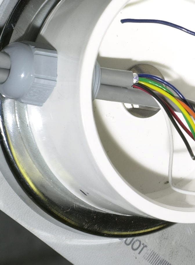
Click to zoom
Application Details
- Equipment Class
- DXT - Part 15 Low Power Transceiver, Rx Verified
- Date of Grant
- Oct 09, 2001
- Application Purpose
- Original Equipment
- Date of Application
- Oct 09, 2001
- Equipment Note
- Low Power RF Transceiver
- Frequency Range
- 903.00000000 - 918.00000000
- Company
- Digi-Star LLC
- Country
- United States
Documents & Files
Document Text
Text extracted from the exhibit documents filed with the FCC. Open a document above to read the original.
Users Manual
The RF900 Wireless Remote User’s Manual Digi-Star Corporation User’s Manual Rev. 0.1 Current RevHardwareSoftware 1.0 1.0 Last Revision DateApril 5, 2001 Mfg. By Digi-Star Corporation 709 West Rockwell Ave. Fort Atkinson, WI 53538 Bruce Johnston, Director of Engineering [email protected] phone 920-563-1400 FAX 920-563-9721 www.Digi-Star.com Users Manual RF900 Wireless remote The RF900 Wireless Remote is a transparent cable replacement for the EZ-R wired remote. The system consists of two ends, one that resides on the top of the truck and the other that resides on the top of the loader. Installation is to be handled by a factory certified dealer. Truck The indicator will be located inside of the feedtruck shown below. The radio will be located on top of the cab of the truck. Your dealer will set the channel during installation. Operation of the indicator will not vary to the user. If during normal usage, performance is less than 300 feet in open field conditions, re-orient the radio on the roof of the truck away from large metal objects until the range improves. If no improvement is made, please call your dealer. Loader The channel selector and the remote are located inside of the loader. The radio enclosure will be placed by your dealer on the top of the loader. Your dealer will have already set and recorded the channel number of each of the available trucks. Turn the remote on and wait until either the weight display or the NODATA message appears on the display. If the no data message appears, re-orient the loader approximately 50 feet in front of truck. If the weight display does not appear press the up arrow button on the remote. You should see the message “CH 01” appear on the display indicating that your radio is set on channel one. Press the up arrow once more to advance the channel number to channel 2. Cycle through the 16 channels and watch for the weight display to appear. If the weight display does not appear after trying all of the channels, check the orientation of the radio attached to the loader. Orient the radio away from any large metal objects and try the channel selection test once again. If there is still no communication, please call your dealer. To tare the indicator in the truck from the remote in the loader, press the tare button once and wait for the red enunciator on the from of the remote to illuminate. Both the radio on the truck and on the loader have low battery detection circuits. Should the message “LOWBAT” appear on the display of the remote, check the battery voltages of both the truck and the loader. Raw power for both radios is provided by the indicator on the truck end and the remote on the loader end. Check the connections. If no source of trouble can be found, please call you r dealer. FCC Statements: WARNING: Changes or modifications to this unit not expressly approved by the party responsible for compliance could void the user's authority to operate the equipment. NOTE: This equipment has been tested and found to comply with the limits for a Class B digital device, pursuant to Part 15 of the FCC Rules. These limits are designed to provide reasonable protection against harmful interference in a residential installation. This equipment generates, uses, and can radiate radio frequency energy and, if not installed and used in accordance with the instructions, may cause harmful interference to radio communications. However, there is no guarantee that interference will not occur in a particular installation. If this equipment does cause harmful interference to radio or television reception, which can be determined by turning the equipment off and on, the user is encouraged to try to correct the interference by one or more of the following measures: ∃ Reorient or relocate the receiving antenna. ∃ Increase the separation between the equipment and receiver. ∃ Consult the dealer or an experienced radio/TV technician for help. This device complies with Part 15 of the FCC rules and and with RSS-210 of Industry & Science Canada. . Operation is subject to the following two conditions: (1) This device may not cause harmful interference, and (2) this device must accept any interference received, including interference that may cause undesired operation. FCC ID Number: PMPRF900
External Photos
Page 1 of 1 10/10/2001file://C:\TCB%20Certifications\Retlif\Retlif%20NH\Dig-Star\Exhibit%20C\External%20... Page 1 of 1 10/10/2001file://C:\TCB%20Certifications\Retlif\Retlif%20NH\Dig-Star\Exhibit%20C\External%20...
ID Label/Location Info
FCC ID: PMPRF900 R
Internal Photos
Page 1 of 1 10/10/2001file://C:\TCB%20Certifications\Retlif\Retlif%20NH\Dig-Star\Exhibit%20C\Internal%20... Page 1 of 1 10/10/2001file://C:\TCB%20Certifications\Retlif\Retlif%20NH\Dig-Star\Exhibit%20C\Internal%20... Page 1 of 1 10/10/2001file://C:\TCB%20Certifications\Retlif\Retlif%20NH\Dig-Star\Exhibit%20C\Internal%20... Page 1 of 1 10/10/2001file://C:\TCB%20Certifications\Retlif\Retlif%20NH\Dig-Star\Exhibit%20C\Internal%20... Page 1 of 1 10/10/2001file://C:\TCB%20Certifications\Retlif\Retlif%20NH\Dig-Star\Exhibit%20C\Internal%20...
Operational Description
Circuit Description For RF900 Wireless remote FCC ID RF section: The RF900 transceiver uses OOK (on/off keying) of a carrier, which can vary from 903 to 918 MHz in 1 MHz channel spacing with 15us bit times as it’s signaling means. The carrier is derived from a PLL (phase lock loop) circuit that is controlled from the microcontroller (CPU). The same 4.000MHz crystal that is used to run the CPU is also used as the reference clock for the PLL. The PLL has a lock detect output that is monitored by the CPU to ensure the carrier is on frequency before transmission is enabled. As a message is built from data set to it from an external device such as a weight indicator, the CPU stores the message until all 105 bits have been received. The message then has a CRC calculated for it. The CPU then enables the transmitter circuit contained in the RF2915 transceiver chip. It then shifts out a serial command code by modulating the final power amp on and off. Logic 1 is represented by carrier on and logic 0 by carrier off. When the amp is powered off during the 0 bits, the signal level drops by about 50dB. When both the transmitter IC and amp are disabled, the signal drops to less than -75dBm. The harmonics are kept low by way of a SAW filter on the output of the final power amp. As the transmission occurs, the receiver end captures the transmitted bits. After all bits have been received, the CRC is calculated and compared to the CRC encoded in the data stream. If the CRC is determined valid, the message is processed for display. If the CRC is erroneous, a counter is started, if a sufficient number of bad messages are received, the “NODATA” message is displayed. After transmission is complete the transmitter goes into receive mode to listen for a request for button command. A request for button command will only occur if the user on the receiver end presses a button on the front panel. Antenna: The antenna is a copper plated wire. The antenna is permanently soldered to the PC board. The antenna input is designed around 50 ohms for easy production testing. Receiver: In receiver mode, the CPU enables an external LNA and internal mixer built into the RF2915 transceiver chip. The RSSI (received signal strength indicator) is monitored by the CPU’s internal analog comparator to look for proper bit patterns from the transmitter. The PLL is set 10.7 MHz below the frequency that is being monitored. As can be assumed from the previous sentence the IF frequency is 10.7 MHz. A SAW filter designed for the 903-918 MHz band allows for improved frequency rejection for out of band interferers. A shield covers the entire RF section of the PC board to eliminate any signal leakage from the PLL to the outside. Surface mounted ferrite beads are used to isolate the inputs and outputs to prevent them from becoming part of the antenna system. Power: The unit uses a voltage regulator IC to maintain 3.3V internal from the 12-volt system on the vehicle.
Schematics
Push button to ground for remote zero activation, 12 volts if RS232 is installed 2 IN 3 GND 1 OUT U4 LM3480 1 GND 2 GND 10 RESET 3 RXTXEN 4 TTL232 5 DIGICLKIN 6 ZEROREQIN 7 RXD232 8 TXD232 9 DIGICLK 11 DIGIDATA 12 ZEROREQOUT 13 RSSI 14 LOWBAT 15 NC1 16 RSW6 30 GND 29 GND 17 BUTTONIN 18 REPEATEN 19 RSW1 20 RSW3 21 RSW4 22 NC2 23 NC3 24 NC4 25 USEUEN 26 RXTXDIP 27 POWER 28 TESTPT C FF EE DD CC BB AA 4 43 32 2 1 1 C FF EE DD CC BB AA 4 43 32 2 1 1 LOCKD BRSSITRACK 1 TXEN 2 RXEN 3 AMPPWR 4 TXDAM 5 FLTRSEL 6 REFOSC 7 PLLCLK 8 PLLDATA 9 PLLLD 10 PWR 11 LOCKD 12 FMDATA 13 RSSI 14 TRACK M1 AMPEN E C B FMMT4403 Q1 V+ 10K R21 PLL-DATPLL-CLKPLL-LD RESETRXD232TXD232 100 R14 SYNCOUT PLL-LD PLLRST 6 NC 7 PD1/TXD 8 PD2/INT0 9 PD3/INT1 10 PD4 11 PD5/OC1A 12 PD6/WR 13 PD7/RD 14 XTAL2 15 XTAL1 1 PB5/MOSI 2 PB6/MISO 3 PB7/SCK 4 RESET 5 PD0/RXD 41 PB1/T1 42 PB2/AN0 43 PB3/AN1 44 PB4/SS 29 ICP 30 PA7/AD7 31 PA6/A6 32 PA5/AD5 33 PA4/AD4 34 PA3/AD3 35 PA2/AD2 36 PA1/AD1 37 PA0/AD0 38 VCC 39 NC 40 PB0/T0 23 PC5/A13 16 GND 17 NC 18 PC0/A8 19 PC1/A9 20 PC2/A10 21 PC3/A11 22 PC4/A12 24 PC6/A14 25 PC7/A15 26 OC1B 27 ALE 28 NC U3AT90S8515-4AI PLL-CLKPLL-DAT RXTXEN RXTXEN TTL232 TTL232 DIGICLKIN ZEROREQIN ZEROREQINDIGICLKDIGIDATAZEROREQOUT LOWBAT RSW6 BUTTONIN REPEATEN RSW1RSW3RSW4 NC1 NC2 NC3 USEUEN USEUEN RXTXDIP RXTXDIP AMPEN 27pF C30 4.00MHz X1 GND TXENRXEN RXEN TXEN LOCKD GND XTAL2 C33 27pF V+ C36 .1uF R13 3.3K V+ GND GND Main CPU & Control RESETBRSSI GND R22 100 DIGICLKINRXD232TXD232DIGICLKDIGIDATAZEROREQOUTLOWBATRSW6BUTTONINREPEATENNC1 Digi-Star OEM GND RXTXENTTL232ZEROREQINRSW1RSW3RSW4NC2 2829301615141312171819202122232425262710 987654321 11 MMT-115-01-L-DH GND B CE Q2 GND POWERNC3USEUENRXTXDIPTESTPT V+ GND 21 REV 1.1 Digi-Star OEM Lab Partners Associates, Inc. 2 1 Jim Clark C FF EE DD CC BB AA 4 43 32 2 1 1 C FF EE DD CC BB AA 4 43 32 2 1 1 GND SLINE 200 x 10 mil SL1 GND 3 RFIN 2 G 5 RFOUT 1 G 4 V+ RF2323 U8 RFV+ 8.2uH L3 GND GND C11 .1uF 18pF C10 R24 330 C42 33pF 1K R28 C21 33pF 15nH L5 C44 8pF 33pF C20 GND C27 33pF GND 23 MODIN 22 LIMOUT 21 DEMODIN 20 GND 19 LIMBP1 18 LIMBP2 17 LIMIN 24 RES+ 1 TXEN 2 TXOUT 3 GND 4 RXIN 5 GND 6 LNAOUT 7 GND 8 MIXIN 31 GAIN 30 VCC3 9 GND 10 MIXOUT 11 VREF 12 RSSI 13 IFIN 14 IFBP1 15 IFBP2 16 IFOUT 28 VCC1 26 OSCBUF 25 RES- 32 RXEN 29 DATAOUT 27 GND CF2 GND R9 1MEG RSSI .01uFC1 .01uFC2 .01uFC3 CF1 B CE Q6 FMMT4401 GND 10K R26 R1 62K C18 33pF GND RFV+ SLINE 500 x 10 mil SL2 500 x 10 mil SL3 SLINE GND GND 1 IN1 2 GND 3 VDD 4 OUT2 5 IN2 6 CTRL 7 GND 8 OUT1 U5RF2425 4pF C34 ANT1 COIL SPRING Digi-Star OEM 3 RFIN 1 G 2 G 4 G 5 RFOUT RF2325 U7 TXDAM RXEN TXEN RFV+ GND 33pF C17 GND FLTRSEL C19 .01uF FB L7 R8 82 AMPPWR VCO C13 33pF GND C14 .1uF GND D1 SMV1215-011 3-10pF VAR FBR2 3300pF C29 TXDFM GND RFV+ GND REFOSCPWR RF MODULE 4.7nH L1 4.7nH L2 4pF C7 2.2uF C15 C9 33pF FB L14 R3FB R10 FB 2.2uF C43 REV 1.1 RSSI 21 BAT54 D2 3300pF C28 1MEG R6 TRACK 4/17/01 GND C40 .1uF FBR4 2.2uF C24 R25 330 33pF C22 GND C4.01uF 18pFC45 .01uFC5 C35 27pF 1 OSCIN 2 OSCOUT 3 VP 4 VCC 5 Do 6 GND 7 Xfin 8 fin 16 oR 15 oP 14 LD 13 ZC 12 PS 11 LE 10 Data 9 Clock U2 MB15E03L VCO 150 R5 GND C25 .01uFC23 .022uF LOCKDPLLDATAPLLCLKPLLLD Jim Clark 2 2 Digi-Star OEM REV 1.1 Lab Partners Associates, Inc.
Test Report
Elite Electronic Engineering, Inc. 1516 Center Circle Downers Grove, IL 60515 Attn:Mr. Richard King Richard: Enclosed you will find a Part 15 Certification Application for a Digi-Star 900MHz Transceiver, FCC ID: PMPRF900. Certification is requested to the requirements of Part 15, Subpart C, Section 15.249 of the Commission’s rules. This application is being filed by Retlif Testing Laboratories on behalf of Digi-Star. I trust that you will find the enclosed application to be complete; however, should you have any questions or require any additional information, please feel free to contact us. Very truly yours, RETLIF TESTING LABORATORIES Scott Wentworth Manager Enc. (as stated) Test Report No. R-3777N1 FCC ID: PMPRF900 APPLICANT Digi-Star LLC 790 West Rockwell Avenue Fort Atkinson, WI 53538 MANUFACTURER SAME TEST SPECIFICATION: FCC Rules and Regulations Part 15, Subpart C, Para. 15.249 TEST PROCEDURE: ANSI C63.4:1992 TEST SAMPLE DESCRIPTION BRANDNAME: Digi-Star MODEL: RF900 TYPE: RF Transceiver (Receiver Verified) POWER REQUIREMENTS: 12VDC via Remote Data Display Unit ANTENNA: Copper Plated Wire (permanently attached) FREQUENCY BAND OF OPERATION: 902MHz to 928MHz TRANSMIT FREQUENCIES: 903MHz to918MHz (16 Discrete Channels) TESTED FREQUENCIES: 903MHz, 911MHz and 918MHz MODULATION: Pulsed (On/Off Keying) TYPE OF TRANSMISSION: Data (Load & Weight Information) EUT CABLE CONFIGURATIONS: (1) 8 Meter Multiconductor Shielded Cable to Rotary Channel Selector Switch (1) 8 Meter Multiconductor Shielded Cable to Remote Display Unit SUPPORT EQUIPMENT: Digi-Star Model EZ-3200 Remote Data Display Unit FCC ID: PMPRF900 RULE SECTION: Part 15, Subpart C, Section 15.249, Operation in the 902 to 928MHz Band TESTS PERFORMED Spurious Emissions 30MHz - 9200MHz (3 transmit frequencies) Field Strength of Fundamental (3 transmit frequencies) Test Report No. R-3777N1 FCC ID: PMPRF900 TEST SAMPLE OPERATION The RF900 Wireless Remote System will be used in the agricultural industry to provide wireless data transfer (load/weight info) between the loader and feedtruck during the loading process. Both the loader and feedtruck will have a RF900 transceiver mounted on the top of the cab so that the loader operator can obtain load/weight information from the truck being loaded. For testing purposes only the EUT was configured to continuously transmit. TEST SAMPLE / TEST PROGRAM CThe fundamental field strengths at 903MHz, 911MHz and 918MHz did not exceed 50mV/M at a test distance of 3 meters. CThe field strength of harmonic emissions did not exceed 500μV/M. No harmonic emissions were observed within 20dB of the specified limit at 3 meter or 1 meter test distances.. CThe field strength of non-harmonic out of band emissions were attenuated more than 50dB below the level of the fundamental or to the limits of 15.209 as applicable. No out of band spurious emissions were observed within 20dB of the specified limit at 3 meter or 1 meter test distances. CRadiated Emissions from the EUT were measured in all three axis. Worst case emissions were found with the EUT in the vertical upright position. This orientation is also the position in which the device will normally be installed. The attached Radiated Emissions test data is representative of this worst case orientation. SPECTRUM ANALYZER Due to the nature of the emissions being measured, care was taken to ensure that the resolution bandwidth of the spectrum analyzer was adequate to provide accurate measurements. GENERAL NOTES 1.All readings were taken utilizing a peak detector function at a test distance of 3 meters. 2.The frequency range was scanned from 30MHz to 9200MHz for spurious emissions. Test Report No. R-3777N1 FCC ID: PMPRF900 EQUIPMENT LISTS Field Strength of Fundamental ENTypeManufacturerDescriptionModel No.Cal DateDue Date 4202BiconilogEMCO26 MHz - 2 GHz31427/10/007/10/01 713EMI Test ReceiverRohde & Schwarz20 Hz - 26.5 GHzESI263/9/005/9/01 Spurious Emissions ENTypeManufacturerDescriptionModel No.Cal DateDue Date 3116Pre-AmplifierMiteq0.1 GHz - 18 GHzAFS42-3511/7/0011/7/01 3258Double Ridge GuideEMCO1 - 18 GHz31155/6/005/6/01 4202BiconilogEMCO26 MHz - 2 GHz31427/10/007/10/01 713EMI Test ReceiverRohde & Schwarz20 Hz - 26.5 GHzESI263/9/005/9/01 Test Report No. R-3777N1 FCC ID: PMPRF900 Job No: Serial No: Date: TransmitAntenna/EUTMeterSiteCorrectedConverted FrequencyPositionReadingCorrectionReadingsReading MHz Polarization/Axis dBuVdBdBuV/muV/m 902.99V/X53.9734.9388.9027861.21 911.00V/X53.3534.9388.2825941.79 918.05V/X54.0835.0089.0828444.61 RF TransceiverTest Sample: Limit @ Operating Mode: FCC Part 15 Paragraph: 15.249 EMISSIONS DATA SHEET Test Method: Customer: Field Strength of Fundamental Digistar CorporationR-3777N1 RF900n/aModel No: Notes: Continuously Transmitting T. Firkowski4/19/01 Peak readings at 3 meters Technician: Test Specification: Data Sheet 1 of 1 3 meters uV/m R-3777N1 RETLIF TESTING LABORATORIES 50000.00 50000.00 50000.00 Job No: Serial No: Date: TestAntennaTurntableMeterCorrectionCorrected Converted FrequencyPositionPositionReadingFactorReadingReading MHz(H/V) - HeightDegreesdBuVdBdBuV/muV/m 30.00------ l------ 88.00------ 88.00------ l------ 216.00------ 216.00------ l------ 960.00------ 960.00------ l------ 9200.00------ RF TransceiverTest Sample: EMISSIONS DATA SHEET Test Method: Customer: Spurious Emissions 30MHz to 9200MHz Digistar CorporationR-3777N1 Fundamental Frequency: 902.99 MHz Limit Operating Mode: Technician: RF900n/aModel No: FCC Part 15 Paragraph: 15.249 Notes: Continuously Transmitting T. Firkowski4/19/01 Peak readings at 3 meters Test Specification: Data Sheet 1 of 3 No EUT spurious emissions were observed within 20dB of the specified limit throughout the given frequency spectrum at 3 Meters uVm 100.00 l 100.00 150.00 l 150.00 200.00 l 200.00 500.00 l 500.00 R-3777N1 RETLIF TESTING LABORATORIES Job No: Serial No: Date: TestAntennaTurntableMeterCorrectionCorrected Converted FrequencyPositionPositionReadingFactorReadingReading MHz(H/V) …
Text truncated - open the document above for the full version.
Test Setup Photos
Page 1 of 1 10/10/2001file://C:\TCB%20Certifications\Retlif\Retlif%20NH\Dig-Star\Exhibit%20C\Test%20Setu... Page 1 of 1 10/10/2001file://C:\TCB%20Certifications\Retlif\Retlif%20NH\Dig-Star\Exhibit%20C\Test%20Setu...
Contact Information
Applicant
Bruce Johnston(Director of Engineering)
Technical Contact
Retlif Testing LaboratoriesScott Wentworth
[email protected]1 603 497-4600
101 New Boston Road · Goffstown, New Hampshire · United States
Test Firm
Retlif Testing LaboratoriesScott Wentworth
Technical Specifications
| # | Rule Parts | Frequency Range | Power Output |
|---|---|---|---|
| 1 | 15C | 903 MHz - 918 MHz | - |