PMSCCBV-320Bus Validator
C & C Enterprise Co., Ltd.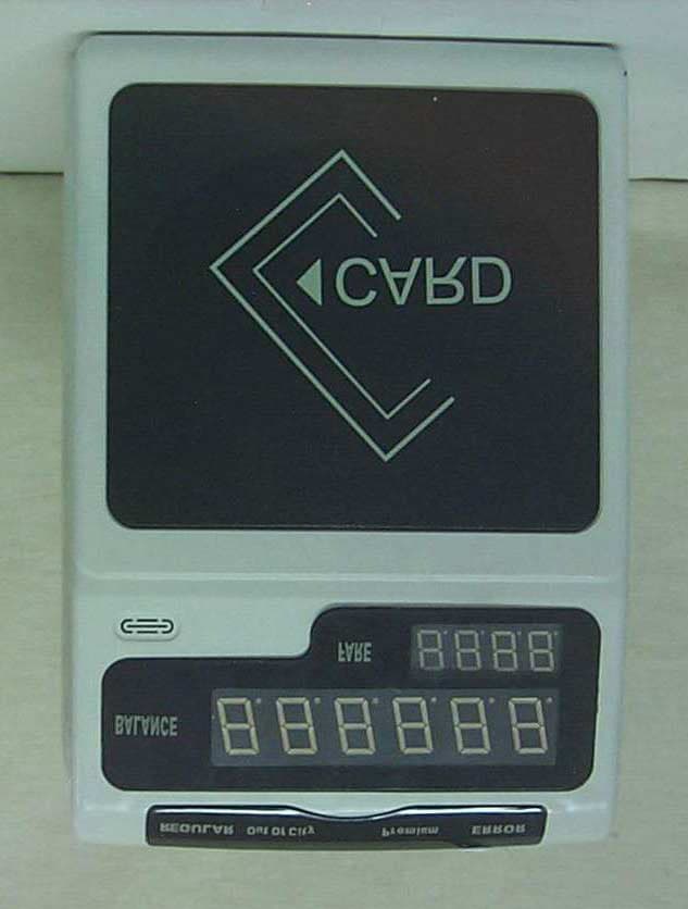
Click to zoom
Application Details
- Equipment Class
- DXX - Part 15 Low Power Communication Device Transmitter
- Date of Grant
- May 17, 2001
- Application Purpose
- Original Equipment
- Date of Application
- May 17, 2001
- Equipment Note
- Bus Validator
- Frequency Range
- 13.56000000 - 13.56000000
- Company
- C & C Enterprise Co., Ltd.
- Country
- South Korea
Documents & Files
Document Text
Text extracted from the exhibit documents filed with the FCC. Open a document above to read the original.
Users Manual
C&C Enterprise Co., LTD Operating Manual [ Bus Validator ] Chapter 1. Summary of Equipment Chapter 2. Appearance and Function Chapter 3. Usage Chapter 4. Technical Specifications Contents Chapter 1. Summary of Equipment This manual is made for describing the appearance, function, usage, precaution and general notice of Bus validator (Model Name : CCBV – 320 ) in order for bus driver to facilitate the operation of it. According to this manual, bus driver can use bus validator before, on and after bus operation and must read carefully this manual to make assurance secure of operating bus before using bus validator. “Note: The manufacturer is not responsible for any Radio or TV interference caused by unauthorized modifications to this equipment. Such modifications could void the user’s authority to operate the equipment.” Chapter 2. Appearance and Function 2.1 Main Features C & C’s Bus Validator is composed of two main parts; Main Unit and Driver’s Control Unit. [ Main Board] [ Driver’s Control Unit ] 2.2 Appearance and Denomination 1) Main Body (1) Front Side Condition Indicator Card Balance Display Speaker Fare Value Display RF Card Antenna (2) Rear Side Fixing Bolt hole for Front and Rear side, Ventilator, Supporting bolt hole, Program Down Load Port, Power switch, Fuse, Driver Keypad connecting Port, Power Terminal A, Power Terminal B. Bolt Hole for fixing Front & Rear Panel Bolt Hole for fixing Front & Rear Panel Ventilator Bolt Hole for Bracket Supporting Bolt Hole Power Switch Fuse Connecting Port for Driver’s Control Unit Connecting Port for Program Downloading Input power Terminal B Input power Terminal A Bolt Hole for Fixing Driver’s Unit 2) Driver’s Control Unit Fare value display Condition Indicator Numeric Buttons Function Buttons Fare Classification Buttons Connecting Port for Main Unit 2,3 Description of Function 1) Selection of Passenger type and number of passenger (1) In case more than 1 passenger : Should select both type & number of passengers. (Passenger type : Adults, Student, Children, or Cancellation) (2) In case on passenger : Automatically recognized by system, no need to operate any buttons. 2) Fare Value Display (1) Card balance : Display card balance as tagging the card. (2) Fare Value : Display fare value as tagging the card. 3) Function Display (1) Regular : light on in case regular value applied. (2) Out of City : light on in case of out of city. (3) Premium : light on in case for premium bus or additional fare needed. (4) Error : light on in case of malfunction. Chapter 3. Operation 3.1 Procedure of Operation 1) Starting Operation (1) Starting the Engine – Ignition on (2) Turning on Validator S/W (3) Checking out conditions of Validator 2) Operation while driving (1) Checking the normal state of Driver’s Control Unit as passenger tag the card. (2) In case one card being used for numbers of people, driver should select buttons for both passenger type and number of passengers. (In case incorrect data was input, select the cancellation button and repeat the above.) (3) In case of balance shortage for fare, reject that passenger. (4) In case of out of city and additional fare needed, select for proper buttons. 3) Operating procedure at closing time of operation (1) Push the button of sum and transmission and check total number of passengers and amount. (2) Once the bus is entered into the garage, collected data is automatically collected into data collector. (3) Turn off the power switch after checking the transmission of data. (4) Turn off the engine. 3.2 Precaution (1) Turn on the power switch of bus validator after starting engine. (2) Bus validator must be protected from outside impact. (3) Never put the bus validator near fire. (4) Make the passengers keep their mind on tagging their card on bus validator within 10 cm. (5) Don’t bring excessive strength to function button in pushing it. (6) Pay attention not to pour water , drink and rain on bus validator. (7) Don’t open the case of validator without permission and make the expert open it. (8) Don’t bring excessive strength to connecting cable and protect it. Chapter 4. Technical Specifications 4.1. Bus Validator (1) Summary Bus Validator, which is installed in the entrance of Bus, reads and validates the RF card and deducts the amount of RF card automatically. The main characteristics of Bus Validator are as follows. -. RF card reading and recording by Contactless RF card. -. Fast reading / Recording process speed: within 0.2 sec. -. Strong structure against vibration, shock. -. Action capability in power alteration. -. Storing of collecting data over 7 days. -. Searching of Black List in off-line. -. Anti sparkling. Block diagram of Bus Validator is shown in figure 1-1. <Figure 1-1> Block diagram of Bus Validator (2) Technical Specifications A. General Specifications 1) Power - Input Power : DC 6 ~ 60V(with surge & over voltage protection) - Input Port : 2ea 2) Environment Condition - Temperature : - 40 °C ~ +125 °C - Relative humidity : 20 ~ 90% 3) Size - Case • Height : 277mm • Width : 195mm • Depth : 80mm - Driver’s Keypad RF MODULE Display Control Main Control Power Supply Antenna Display Keypad for Driver (Page Up / Page Down) • Height : 155mm • Width : 128mm • Depth : 60mm 4) Weight : 2.5Kg B. Performances 1) RF Card Validating - Validating Type : Contactless reading and writing - Valdating Speed : Within 0.2 Sec. 2) Display - Fare Display : 7 Segment LED Display x 4digits - Balance and passenger Display : 7 Segment LED Display x 6digits - Operation Status Display : 2 Lamps (OK, Error, ) 3) Main Control Board -Control Type : Program Control -CPU : 32Bit Microprocessor (XC68307CFG16) -Memory Capacity • Booting Memory: 32KB • Application Program Memory : 224KB • Data Memory : 64KB • Transaction Record : 128KB • Transaction Data Back-up Memory : 8Mbit -Model : KM29W32000AT -Data Retention : 10Year -SAM : 68S711E9CFN2 -Communication Interface • Communication Type : RS-232C Serial • Transaction Speed : 9…
Text truncated - open the document above for the full version.
Block Diagram
Bus Validator [ Block Diagram ] C.P.U. ROM Driver Panel Speaker Flash Memory RAM RTC SAM(Security Access Module) Digit Display LED Display RF Module Program Down Load Port UART Power Input 16 MHz 8 MHz 3.69 MHz
ID Label/Location Info
FCC ID. : PMSCCBV-320 ONETECH Testing & Evaluation Lab. IDENTIFICATION LABEL LOCATION: PROPOSED FCC ID LABEL The label of FCC ID. will be affixed to the bottom side of product. FCC ID : PMSCCVB-320 Model Name: CCVB-320 This device complies with Part 15 of the FCC Rules. Operation is subject to the following two conditions: (1) this device may not cause harmful interference, and (2) this device must accept any interference received, including interference that may cause undesired operations C&C Enterprise Co., Ltd. Made in Korea
Operational Description
Operational Description Bus Validator, which is installed in the entrance of Bus, reads and validates the RF card and deducts the amount of RF card automatically. The main characteristics of Bus Validator are as follows. -. RF card reading and recording by Contactless RF card (13.56MHz) -. Fast reading / Recording process speed: within 0.2 sec. -. Strong structure against vibration, shock -. Action capability in power alteration -. Storing of collecting data over 7 days -. Searching of Black List in off-line -. Anti sparkling Block diagram of Bus Validator is shown in figure 1-1. <Figure 1-1> Block diagram of Bus Validator RF MODULE Display Control Unit Main Control Board Power Supply Antenna Display Keypad for Driver (Page Up / Page Down)
Test Report
Page 1 of 14 FCC ID. : PMSCCBV-320 File No. : E013R-056 This report shall not be reproduced except in full without our written approval. EMC-004 (Rev.0) HEAD OFFICE : #505 SK APT. Factory 223-28, Sangdaewon 1 Dong, Jungwon-Gu, Seongnam-City, Kyunggi-Do, 462-121, Korea (TEL: 82-31-746-8500 FAX: 82-31-746-8700 ) EMC Testing Dept : 426-1 Daessangryung-Ri, Chowol-Myun, Kwangju-Kun, Kyunggi-Do 464-860 Korea. (TEL: 82-31-765-8289 FAX: 82-31-766-2904) ONETECH Testing & Evaluation Lab. E LECTROMAGNETIC E MISSION C OMPLIANCE R EPORT FOR FCC CERTIFICATION Test report file number : E013R-056 Applicant : C&C ENTERPRISE CO., LTD. Address : 261, Nonhyun-Dong, Kangnam-Ku, Seoul, 135-010, Korea Manufacturer : C&C ENTERPRISE CO., LTD. Address : 261, Nonhyun-Dong, Kangnam-Ku, Seoul, 135-010, Korea Type of Equipment : BUS VALIDATOR FCC ID : PMSCCBV-320 Model / Type No. : CCBV-320 Serial number : N/A Total page of Report : 14 pages (including this page) Date of Incoming : April 09, 2001 Date of Issuing : May 18, 2001 SUMMARY The equipment complies with the regulation of FCC CRF 47 PART 15, SUBPART C, SECTION 15.225, 15.209. This test report contains only the results of a single test of the sample supplied for the examination. It is not a general valid assessment of the features of the respective products of the mass-production. Prepared by: Approved by: G. W. Lee/ Assist. Chief Engineer Y. K. Kwon / Chief Engineer EMC Dept. EMC Dept. ONETECH Corp. ONETECH Corp. Page 2 of 14 FCC ID. : PMSCCBV-320 File No. : E013R-056 This report shall not be reproduced except in full without our written approval. EMC-004 (Rev.0) HEAD OFFICE : #505 SK APT. Factory 223-28, Sangdaewon 1 Dong, Jungwon-Gu, Seongnam-City, Kyunggi-Do, 462-121, Korea (TEL: 82-31-746-8500 FAX: 82-31-746-8700 ) EMC Testing Dept : 426-1 Daessangryung-Ri, Chowol-Myun, Kwangju-Kun, Kyunggi-Do 464-860 Korea. (TEL: 82-31-765-8289 FAX: 82-31-766-2904) ONETECH Testing & Evaluation Lab. CONTENTS Page 1. VERIFICATION OF COMPLIANCE ...............................................................................................................3 2. GENERAL INFORMATION ................................................................................................................................4 2.1 P RODUCT D ESCRIPTION .............................................................................................................................................4 2.2 R ELATED S UBMITTAL ( S ) / G RANT ( S ) ......................................................................................................................4 2.3 T EST S YSTEM D ETAILS ..............................................................................................................................................4 2.4 T EST M ETHODOLOGY ................................................................................................................................................4 2.5 T EST F ACILITY ............................................................................................................................................................5 3. SYSTEM TEST CONFIGURATION .................................................................................................................5 3.1 J USTIFICATION ............................................................................................................................................................5 3.2 EUT EXERCISE S OFTWARE .......................................................................................................................................5 3.3 C ABLE D ESCRIPTION ..................................................................................................................................................5 3.4 N OISE S UPPRESSION P ARTS ON C ABLE ...................................................................................................................5 3.5 E QUIPMENT M ODIFICATIONS ....................................................................................................................................6 3.6 C ONFIGURATION OF T EST S YSTEM ..........................................................................................................................6 3.7 A NTENNA R EQUIREMENT ..........................................................................................................................................6 4. PRELIMINARY TEST ............................................................................................................................................7 4.1 AC P OWER LINE C ONDUCTED E MISSION T EST ......................................................................................................7 4.2 R ADIATED E MISSION T EST ........................................................................................................................................7 5. FINAL RESULT OF MEASURMENT .............................................................................................................8 5.1 C ONDUCTED E MISSION T EST ....................................................................................................................................8 5.2 R ADIATED E MISSION T EST BELOW 30 MH Z ..........................................................................................................9 5.2 R ADIATED E MISSION T EST FROM 30 MH Z TO 1000 MH Z .................................................................................10 5.3 F REQUENCY S TABILITY T EST -I NPUT DC V OLTAGE ............................................................................................11 5.4 F REQUENCY S TABILITY T EST -T EMPERATURE .....................................................................................................12 7. LIST OF TEST EQUIPMENT ............................................................................................................................14 Page 3 of 14 FCC ID. : PMSCCBV-320 File No. : E013R-056 …
Text truncated - open the document above for the full version.
Test Setup Photos
Radiated Emission Test
Contact Information
Applicant
Jin-Soo Soh(General Manager)
Test Firm
ONETECH Corp.Y. Kwon
Technical Specifications
| # | Rule Parts | Frequency Range | Power Output |
|---|---|---|---|
| 1 | 15C | 13.56 MHz - 13.56 MHz | - |