PNEUBTXR19Remote Control Transmitter
FSL Electronic's Ltd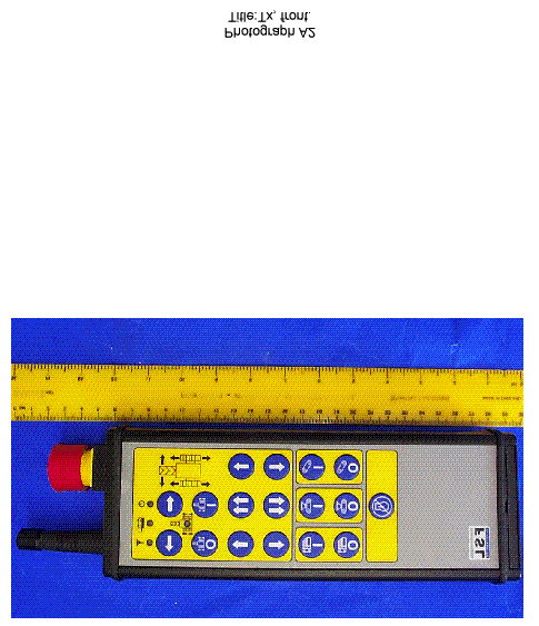
Click to zoom
Application Details
- Equipment Class
- DSC - Part 15 Security/Remote Control Transmitter
- Date of Grant
- Sep 02, 2001
- Application Purpose
- Original Equipment
- Date of Application
- Sep 02, 2001
- Equipment Note
- Remote Control Transmitter
- Frequency Range
- 433.68000000 - 434.08000000
- Company
- FSL Electronic's Ltd
- Country
- Ireland
Documents & Files
Document Text
Text extracted from the exhibit documents filed with the FCC. Open a document above to read the original.
Users Manual
Page 1 of 6 OPERATING INSTRUCTIONS FOR FSL ELECTRONICS LTD “ULTRATRACK” REMOTE CONTROL SYSTEM Page 2 of 6 1.0 TRANSMITTER OPERATION: The figure below shows the transmitter unit with an explanation of each function. TRANSMITTER E-STOP SWITCH BATTERY CHARGING SOCKET RADIO ANTENNA POWER INDICATOR BATTERY CHARGING INDICATOR RADIO TRANSMIT INDICATOR BATTERY AND DIP SWITCH COVER SWIVEL CONVEYER LEFT CONTROL SWIVEL CONVEYER RIGHT CONTROL ENGINE STOP CONTROL GRID START CONTROL GRID STOP CONTROL HOPPER START CONTROL HOPPER STOP CONTROL MAIN CONVEYER START CONTROL MAIN CONVEYER STOP CONTROL Page 3 of 6 MOVEMENT MODE ON CONTROL MOVEMENT MODE OFF CONTROL TRACK MOVEMENT MODE INDICATOR BOTH TRACKS FORWARD CONTROL TRACK LEFT- FORWARD CONTROL TRACK RIGHT- FORWARD CONTROL TRACK LEFT- REVERSE CONTROL TRACK RIGHT- REVERSE CONTROL BOTH TRACK REVERSE CONTROL Page 4 of 6 1.1 TRANSMITTER OPERATION: The power to the transmitter is activated by pulling the E-STOP control outwards. The E- STOP will be heard to click. The green power indicator will illuminate. The transmitter should be switched off after operation or during battery charging. This is carried out by pressing the E-STOP switch inwards. 1.2 TRACK MOVEMENT OPERATION: The system is placed into track movement mode by pressing the MOVEMENT MODE ON control on the transmitter. This will send an enable code to the receiver unit to start a seven- second delay before any track movement can be made. During this time a warning sirem / beacon will be activated (if fitted by the machine manufacturer). On the transmitter unit the movement mode indicator will flash rapidly for seven-seconds. After this initial delay the indicator will flash slowly and the track movement controls can be operated. If any track movement controls are pressed during the movement on delay the controls and delay will be disabled until the switches are released. The movement mode can be deselected by pressing the MOVEMENT MODE OFF control. If any other function is pressed (i.e. hopper, conveyer, swivel and engine stop controls) the track movement mode will be disabled. The track movement mode indicator will be extinguished. 1.3 ENGINE STOP CONTROL: The ENGINE STOP control will send a signal to the receiver unit to stop the engine on the machine. It will also be sent if the transmitter E-STOP control is activated. THIS CONTROL SHOULD NOT BE CONSIDERED AS BEING PART OF THE MACHINE EMERGENCY STOP SYSTEM! 1.4 CONVEYER SWIVEL LEFT AND RIGHT CONTROLS: Pressing the appropriate control on the transmitter will activate the out-feed swivel conveyer left and right controls. This will also disable the track movement mode. 1.5 MAIN CONVEYER START AND STOP CONTROLS: Pressing the appropriate control will start or stop the main conveyer on the machine. 1.6 HOPPER CONVEYER START AND STOP CONTROLS: Pressing the appropriate control will start or stop the hopper conveyer on the machine. 1.6 GRID START / STOP CONTROLS: Pressing the appropriate control will start or stop the programmed up and down cycle of the grid on the machine. Page 5 of 6 2.0 BATTERY CHARGING: Inserting the provided charging lead into the socket at the top of the transmitter unit will charge the rechargeable battery. The yellow charge indicator will illuminate to show that a charging voltage is present. It will take 10 hours to provide a full charge of the battery. The charging lead should only be connected to an automotive type cigar socket supply between 12V – 24V DC! The transmitter can also be powered by the charger lead (by pulling the E-STOP to the outwards position) 3.0 DIP SWITCH SETTING: The Transmitter code setting can be adjusted to suit a particular receiver unit. This is achieved by an eight-way DIP switch at the bottom of the transmitter unit, behind the battery cover. Contact the machine manufacturer or FSL Electronics Ltd for further information on setting up particular codes. 4.0 TROUBLE SHOOTING GUIDE: If the remote control system does not appear to operate then the following steps should be carried out before contacting technical support. • Ensure that the transmitter is switched on! (By pulling the E-STOP switch outwards). • Check that the green power indicator is illuminated on the transmitter. • If the power indicator does not light make sure that the battery is fully charged. • Check that the charging indicator illuminates when inserted to the transmitter and connected to a supply. • Check the operation of the transmitter with the charging lead connected to a supply. • Make sure that the transmitter is transmitting a signal by checking the red transmit indicator when an appropriate control switch is pressed. • Check that the remote control receiver on the machine is being provided with power by checking the power indicator in the receiver unit. • Ensure that the transmitter and receiver are set for the same code. Check the signal-receive and valid code indicators on the receiver are illuminated when a control function is activated on the transmitter. If only the signal receive indicator illuminates then the transmitter DIP-switches need to be adjusted to suit the receiver unit. Page 6 of 6 5.0 TECHNICAL SPECIFICATION: Supply Voltage 1 X 9V Alkaline battery, type 6AM6, 6F22, PP3 (non rechargeable units) 1 X 9V Nickel Metal Hydride, type GP 15F8H Power Consumption Activated: max 24mA De-activated: max 2mA Range Dependant on surroundings and conditions Typical 100m Transmission Type UHF Radio 433.92 Mhz Operating Temperature -20 o C to 55 o C Housing Black Aluminium extrusion IP65 Channels 1 to 19 NOTICE: All information contained within this manual is copyright to FSL Electronics Limited, 2001. FSL Electronics Limited reserve the right to change this manual and specification of products without prior notice For further technical information please contact FSL Electronics Limited Sandholes Road Cookstown Co. Tyrone, N. Ireland, BT80 9AR TEL: +44 (0) 28 8676 6131 FAX: +44 (0) 28 8676 6414 www.fsl.ltd.uk e-mail technical@fs…
Text truncated - open the document above for the full version.
ID Label/Location Info
FCC ID LABEL FOR FSL ELECTRONICS LTD “ULTRATRACK” TRANSMITTER
ID Label/Location Info
FCC ID LABEL FOR FSL ELECTRONICS LTD “ULTRATRACK” TRANSMITTER
Parts List/Tune Up Info
PIC_TRANSMITTER_EXTRUSION_VER2C DesignatorPart Type C1100NF C2100NF C322uF/16V TANT C41000uF/16V C51000uF/16V C64u7F/35V C74u7F/35V C81000uF/16V CN2PP3 BATT CONNECTOR CN42.1mm DC SOCKET D1GRN LOW CURR LED D10IN4148 D11IN4148 D12IN4148 D13GRN LOW CURR LEDR D14IN4148 D15IN4148 D3IN4148 D4RED LOW CURR LED D8YEL LOW CURR LED D9BAT49 Q5BS170 Q7BS170 Q8BS110 R182R R101K5 R112K2 R12560R R1352R R1452R R1547K R16470K R171K R182K2 R2100R R322K R410K R510K R610K R710K R81K5 R91K5 RG1LP2905CZ RG2LM317LZ RM1ZEZEX ZSM560 RM2ZEZEX ZSM560 RS12K2 RS22K2 RS3100R RS4100R RS5100R Page 1 of 2 PIC_TRANSMITTER_EXTRUSION_VER2C RS6100R RV1GNR05D330K SW1K12A-BK-5N SW10K12A-BK-5N SW11K12A-BK-5N SW12K12A-BK-5N SW13K12A-BK-5N SW14K12A-BK-5N SW15K12A-BK-5N SW16K12A-BK-5N SW17K12A-BK-5N SW18K12A-BK-5N SW19K12A-BK-5N SW2K12A-BK-5N SW208 - WAY DIP SWITCH SW3K12A-BK-5N SW4K12A-BK-5N SW5K12A-BK-5N SW6K12A-BK-5N SW7K12A-BK-5N SW8K12A-BK-5N SW9K12A-BK-5N TX1TXM433 TRANSMITTER U1PIC16F873-04/SP XT14MHz (3-PIN) ZD112V 1.3W ZENER HANDSET ENCLOSURE E-STOP SWITCH E-STOP SWITCH N/C CONTACT E-STOP SWITCH N/O CONTACT 433MHz HELICAL AERIAL PCB PCB BASE BOARD M3 x 10mm F-F HEX SPACERS (X8) M3 x 6mm POZIDRIVE SCREWS (X16) M4 HEX NUT M4 SOLDER TAG M4 x 3mm SCREW INSULATOR Page 2 of 2
Test Report
EU1554/3256Page 1 of 19 RF196-iss01 TEST REPORT NO:EU1554/3256 COPY NO:............ ISSUE NO:1 FCC ID: PNEUBTXR19 REPORT ON THE CERTIFICATION TESTING OF A FSL ELECTRONICS LIMITED ULTRATRACK TRANSMITTER WITH RESPECT TO THE FCC 47CFR, Pt’s 15.231 AND 15.209, INTENTIONAL RADIATOR SPECIFICATIONS TEST DATE(s): 13 th & 14 th JUNE 2001 TESTED BY:....................................................J CHARTERS APPROVED BY:....................................................S P HAYES ISSUE DATE:.................................................... Distribution Copy No’s:- 1FSL ELECTRONICS LIMITED 2TRL EMC Ltd EU1554/3256Page 2 of 19 RF196-iss01 CONTENTS page APPLICANT'S SUMMARY3 CERTIFICATE OF CONFORMITY & COMPLIANCE4 DESCRIPTION OF TRANSCEIVER4 EQUIPMENT TEST CONDITIONS5 TESTS REQUIRED6 SAMPLE CALCULATIONS6 TEST RESULTS7 - 8 PHOTOGRAPHSANNEX A[X] PHOTOGRAPH No 1:Test site with TxANNEX A1 PHOTOGRAPH No 2:Tx, front.ANNEX A2 PHOTOGRAPH No 3:Tx, rear.ANNEX A3 PHOTOGRAPH No 4:Tx, rf pcb, top.ANNEX A4 PHOTOGRAPH No 5:Tx, rf pcb, bottom.ANNEX A5 PHOTOGRAPH No 6: TX rf pcb, with coverANNEX A6 TEST EQUIPMENT LISTANNEX B [X] APPLICANT'S SUBMISSION OF DOCUMENTATION LISTANNEX C[ ] MEASURING DISTANCE EXTRAPOLATION GRAPH(s)ANNEX D[ ] TRANSMITTER CARRIER FREQUENCY GRAPH(s)ANNEX E[ ] OCCUPIED BANDWIDTH (part 15.231c)ANNEX F[X] Notes:- 1.Component failure during testYES[ ] NO[X] 2.If Yes, details of failure:- 3.All measurement uncertainty calculations detailed in this report are carried out in accordance with UKAS Publication NIS 81, Edition 1, May 1994, for a 95% confidence level. 4.The contents of the attached applicant’s declarations and other supplied information are not covered by the scope of this laboratory’s UKAS or FCC accreditations and is provided in good faith. EU1554/3256Page 3 of 19 RF196-iss01 APPLICANT'S SUMMARY EQUIPMENT UNDER TEST (EUT):ULTRATRACK EQUIPMENT TYPE:DIGGER CONTROL TRANSMITTER SERIAL NUMBER OF EUT:Engineering sample PURPOSE OF TEST:FCC CERTIFICATION TEST SPECIFICATION(s):FCC 47CFR Pt’s 15.231, 15.209 TEST RESULT:COMPLIANTYES[X] NO[ ] APPLICANT’S CATEGORY:( a ) MANUFACTURER[X] ( b ) IMPORTER[ ] ( c ) DISTRIBUTOR[ ] ( d ) AGENT[ ] APPLICANT'S ORDER No(s):15022 APPLICANT’S CONTACT PERSON:PAUL BRENNAN APPLICANT:FSL ELECTRONICS LIMITED ADDRESS:SANDHOLES ROAD COOKSTOWN Co. TYRONE BT80 9AR TEL: +44 (0) 28 867 66131 FAX: +44 (0) 28 867 62414 MANUFACTURER:FSL ELECTRONICS LIMITED ADDRESS:SANDHOLES ROAD COOKSTOWN Co. TYRONE BT80 9AR TEL: +44 (0) 28 867 66131 FAX: +44 (0) 28 867 62414 EUT(s) COUNTRY OF ORIGIN:UNITED KINGDOM TEST LABORATORY:TRL EMC LTD UKAS ACCREDITATION No:0728 TEST DATE(s):13 th & 14 th JUNE 2001 TEST REPORT No:EU1554/3256 EU1554/3256Page 4 of 19 RF196-iss01 CERTIFICATE OF CONFORMITY & COMPLIANCE FCC IDENTITY:PNEUBTXR19 PURPOSE OF TEST:FCC Certification TEST SPECIFICATION:FCC 47CFR, Parts 15.231, 15.209 TEST RESULT:Compliant to Specification EQUIPMENT UNDER TEST:ULTRATRACK EQUIPMENT SERIAL No:Engineering Sample ITU EMISSION CODE:160KF1DAN EQUIPMENT TYPE:Remote Control Transmitter UTILISATION:Telecommand for Outdoor Machinery CARRIER EMISSION:77.1dBFV/m @ 3m ANTENNA TYPE:Fixed, or Integral ALTERNATIVE AE:None, as per Part 15.203 BAND OF OPERATION:410.00MHz - 470.00MHz CHANNEL SPACING:Not applicable No. of CHANNELS:1 FREQUENCY GENERATION:SAW Resonator [X] ;Crystal[ ] ;Synthesizer[ ] MODULATION METHOD:Amplitude [ ] ;Digital [X] ;Angle[ ] POWER SOURCE(s):9Vdc battery TEST DATE(s):13 th & 14 th JUNE 2001 ORDER No(s):15022 APPLICANT:FSL ELECTRONICS LIMITED COOKSTOWN Co. TYRONE BT80 9AR TESTED BY:...............................................................J CHARTERS APPROVED BY:...............................................................S P HAYES EMC MANAGER EU1554/3256Page 5 of 19 RF196-iss01 EQUIPMENT TEST CONDITIONS 1. EQUIPMENT SERIAL / MODEL IDENTITY CHANNEL NUMBER Tx NOMINAL FREQUENCY MHz Rx NOMINAL FREQUENCY MHz TESTS REQUIRED REMARKS ULTRATRACK 1433.9N/ATX radiatedPt15.209 TX carrierPt15.249 2.Equipment category:Single channel[X] Two channel[ ] Multi-channel[ ] 3.Supply voltages:Vnom=9Vdc Note:-Vnom voltages are as stated above unless otherwise shown on the test report page. 4.Temperatures:(Ambient)Tnom=[see test] 5.Transmitter maximum deviation or shift:kHz=n/a 6.Transmitter maximum bit or pulse rate & level:bps=160K/bps Level=Internal 7.Channel spacing:kHz= Narrowband[ ] Wholeband[X] EU1554/3256Page 6 of 19 RF196-iss01 TESTS REQUIRED TRANSMITTER & RECEIVER TESTS Transmitter Spurious Emissions - Powerline - Part 15.207[ ] Transmitter Spurious Emissions - Radiated - Part 15.209[X] Transmitter Carrier Emission - Radiated - Part 15.231[X] Transmitter Carrier Frequency- Radiated - Part 15.231[X] Notes:- 1.Equipment tested for (mains ac) 110V powerline emissions.[n/a] 2.Equipment tested as (fixed) integral antenna configuration.[X] 3.All tests were carried out with new batteries, as per Part 15.31.e.[X] 4.Equipment tested for radiated emissions as per Part 15.209.[X] 5.Equipment tested for radiated emissions as per Part 15.231[X] 6.Equipment tested for unintentional radiator digital device Class B[n/a] SAMPLE CALCULATIONS Parts 15.209 & 15.231 - Radiated. Frequency (MHz) Rx (dBFV) Ae AF & Cable loss (dB/m & dB) Field Strength @ 3m (dBFV/m) 433.958.316.4 2.4 77.1 (7079FV/m) Part 15.231 - Limit is calculated as follows: FCC Part numberFc (MHz) (125/3)*Fc(MHz)-(21250/3) (FV/m) Limit @ 3m ( FV/m ) 15.231433.941.667*433.9-7083.333 10996 FV/m EU1554/3256Page 7 of 19 RF196-iss01 TRANSMITTER TESTS TRANSMITTER SPURIOUS EMISSIONS - RADIATED - PART 15.209.c - >30MHz Ambient temperature=16EC (<1GHz),22EC (>1GHz)3m measurements <1GHz[X] Relative humidity=54% (<1GHz),54% (>1GHz)1m measurements >1GHz[ ] Conditions=Open Area Test Site (OATS)3m extrapolated from 1m[ ] Supply voltage=9Vnom Channel number=1 Frequency & Level 30MHz to 88MHz nil emission>-20 below limit Frequency & Level 88MHz to 216MHz nil emission>-20dB below limit Frequency & Level 216MHz to 960MHz nil emission>-20dB below limi…
Text truncated - open the document above for the full version.
Contact Information
Applicant
John M Meenan(Director)
Technical Contact
FSL Electronics LtdPaul Brennan
[email protected]44 2886766131
Sandholes Road · Cookstown · United Kingdom
Non-Technical Contact
FSL Electronics LtdJohn Meenan
[email protected]44 2886766131
Test Firm
TRL EMC LimitedNeil Roche
Technical Specifications
| # | Rule Parts | Frequency Range | Power Output |
|---|---|---|---|
| 1 | 15.231 | 433.68 MHz - 434.08 MHz | - |