PNY-ODU4028GMESHWORKS System for LMDS
Radiant Networks Plc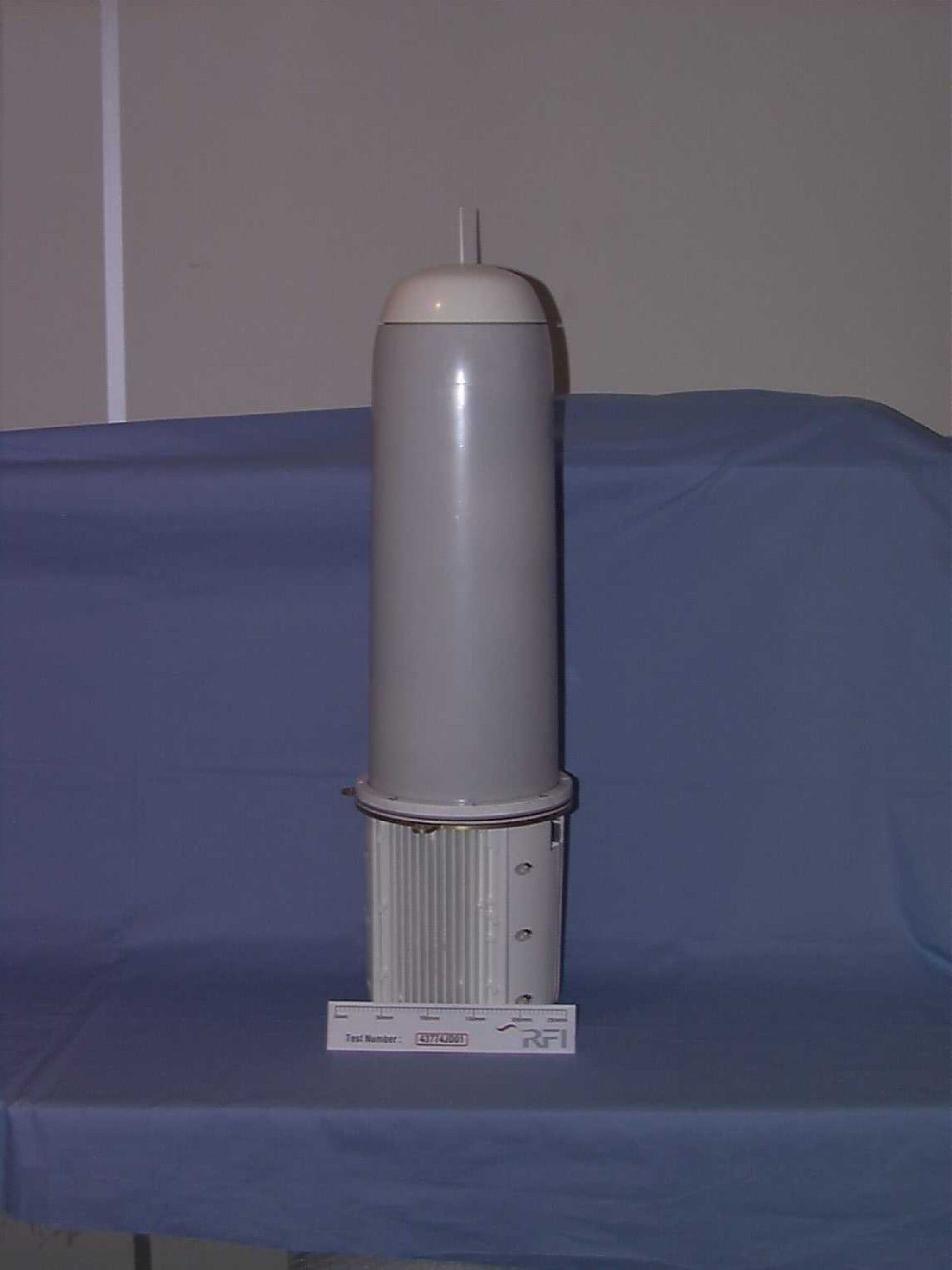
Click to zoom
Application Details
- Equipment Class
- TNB - Licensed Non-Broadcast Station Transmitter
- Date of Grant
- Sep 09, 2002
- Application Purpose
- Original Equipment
- Date of Application
- Sep 09, 2002
- Equipment Note
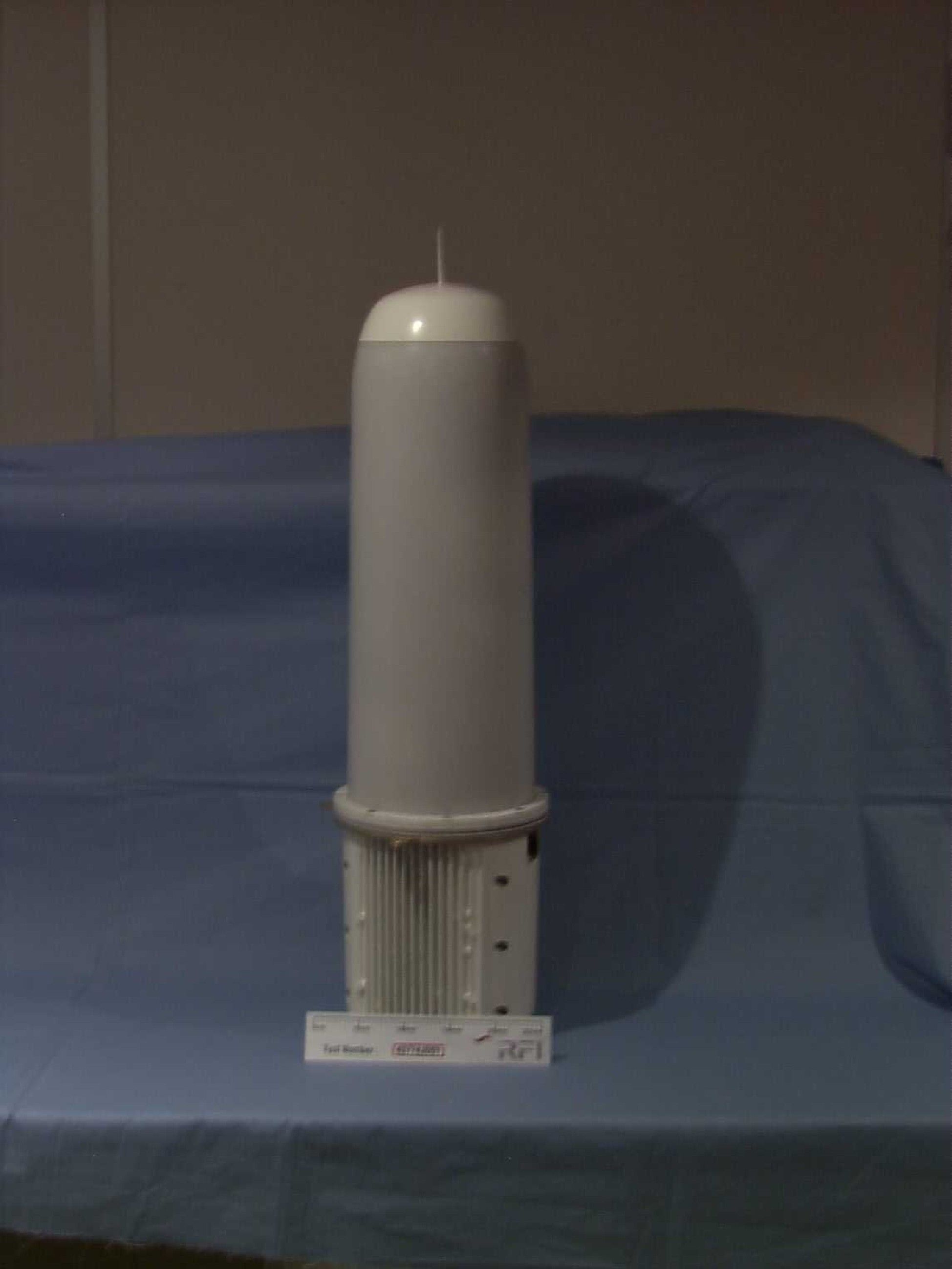
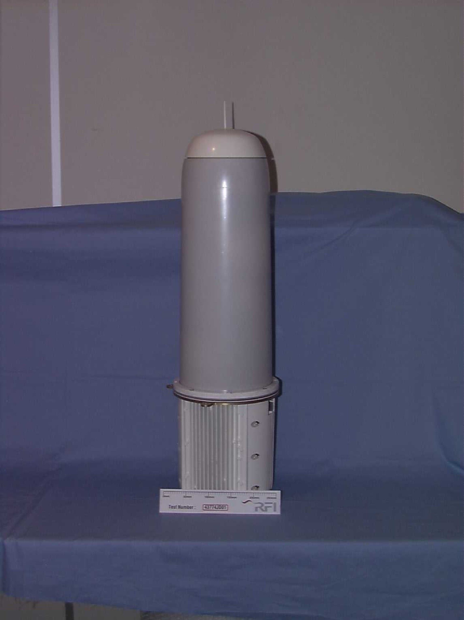
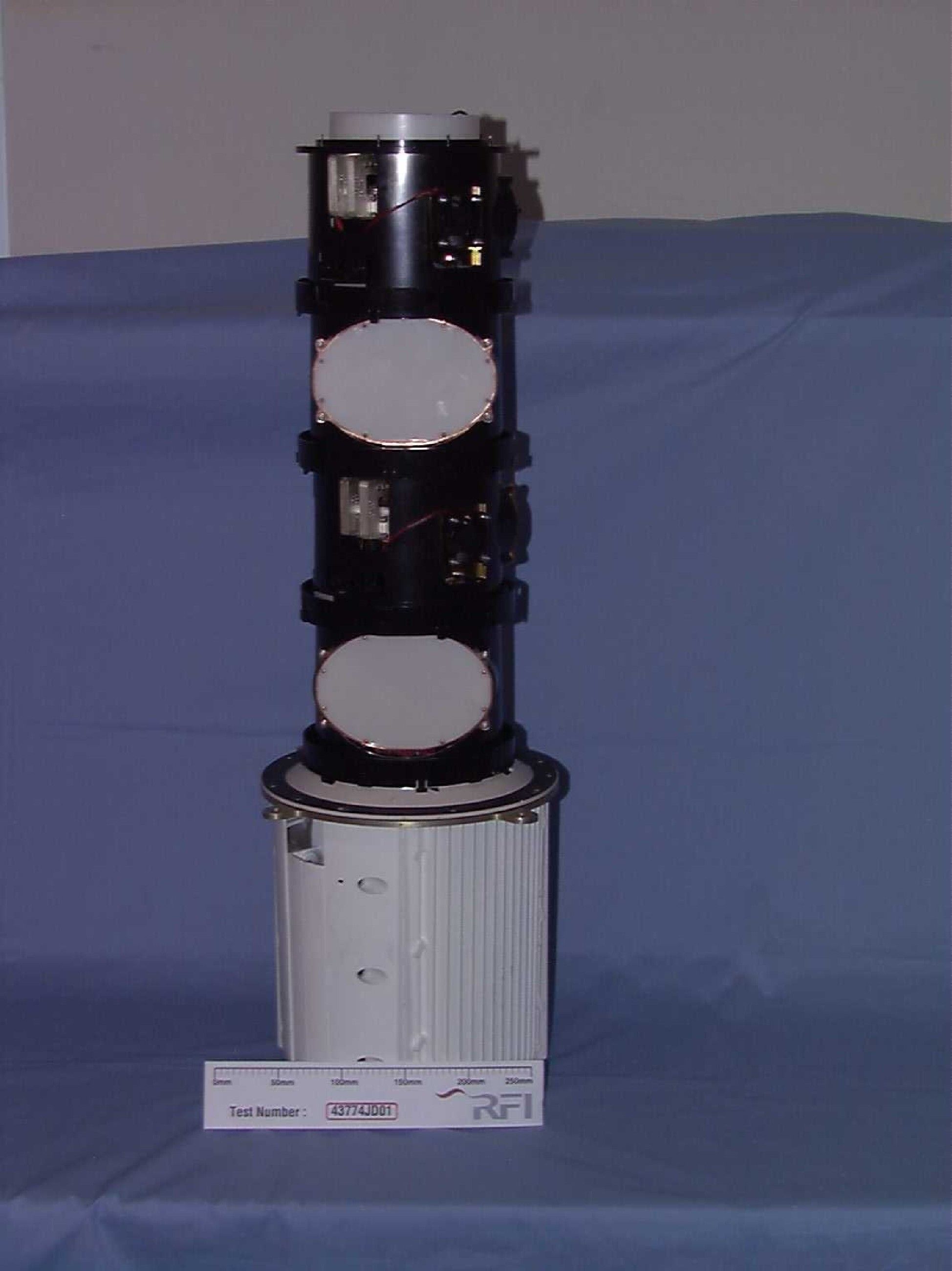
- MESHWORKS System for LMDS
- Frequency Range
- 27500.00000000 - 28350.00000000
- Company
- Radiant Networks Plc
- Country
- United Kingdom
Documents & Files
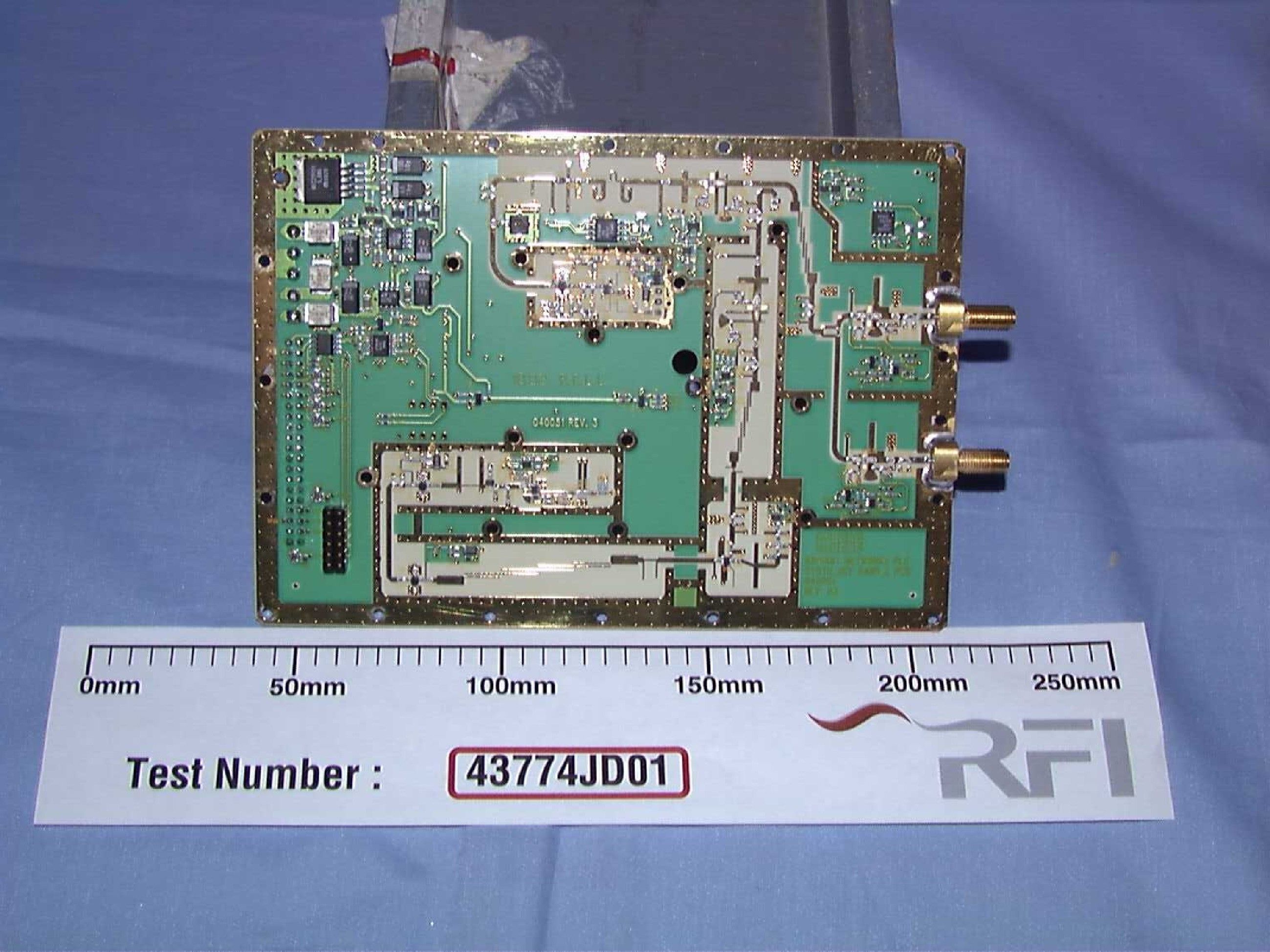
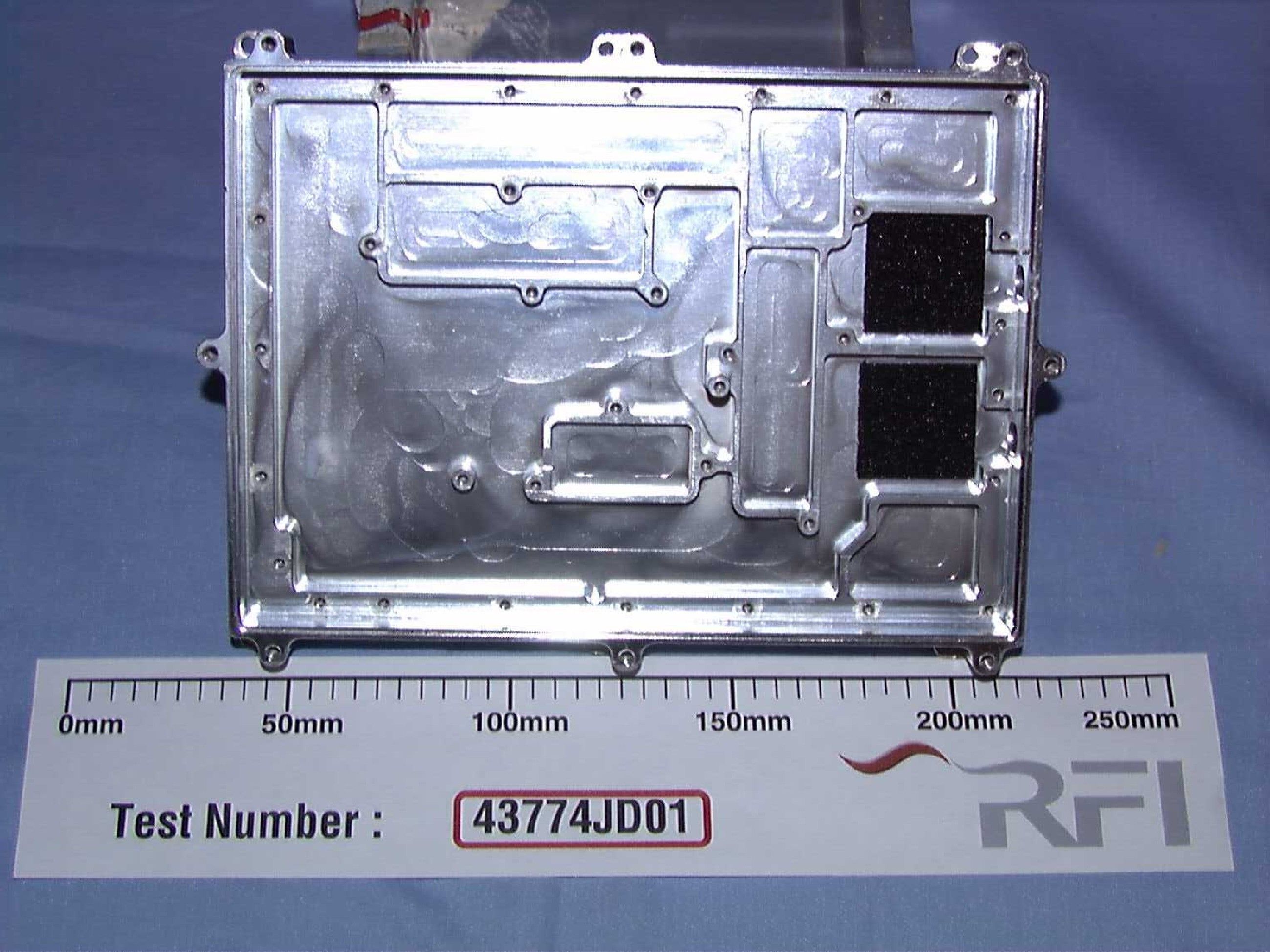
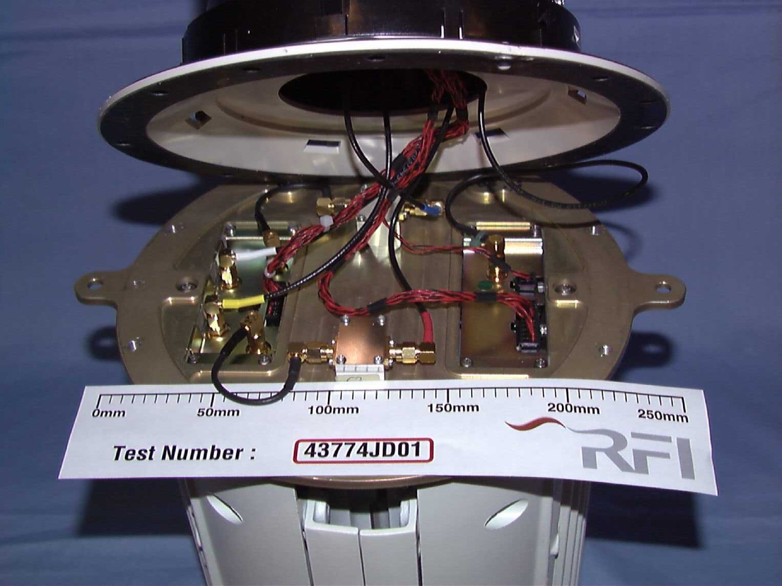
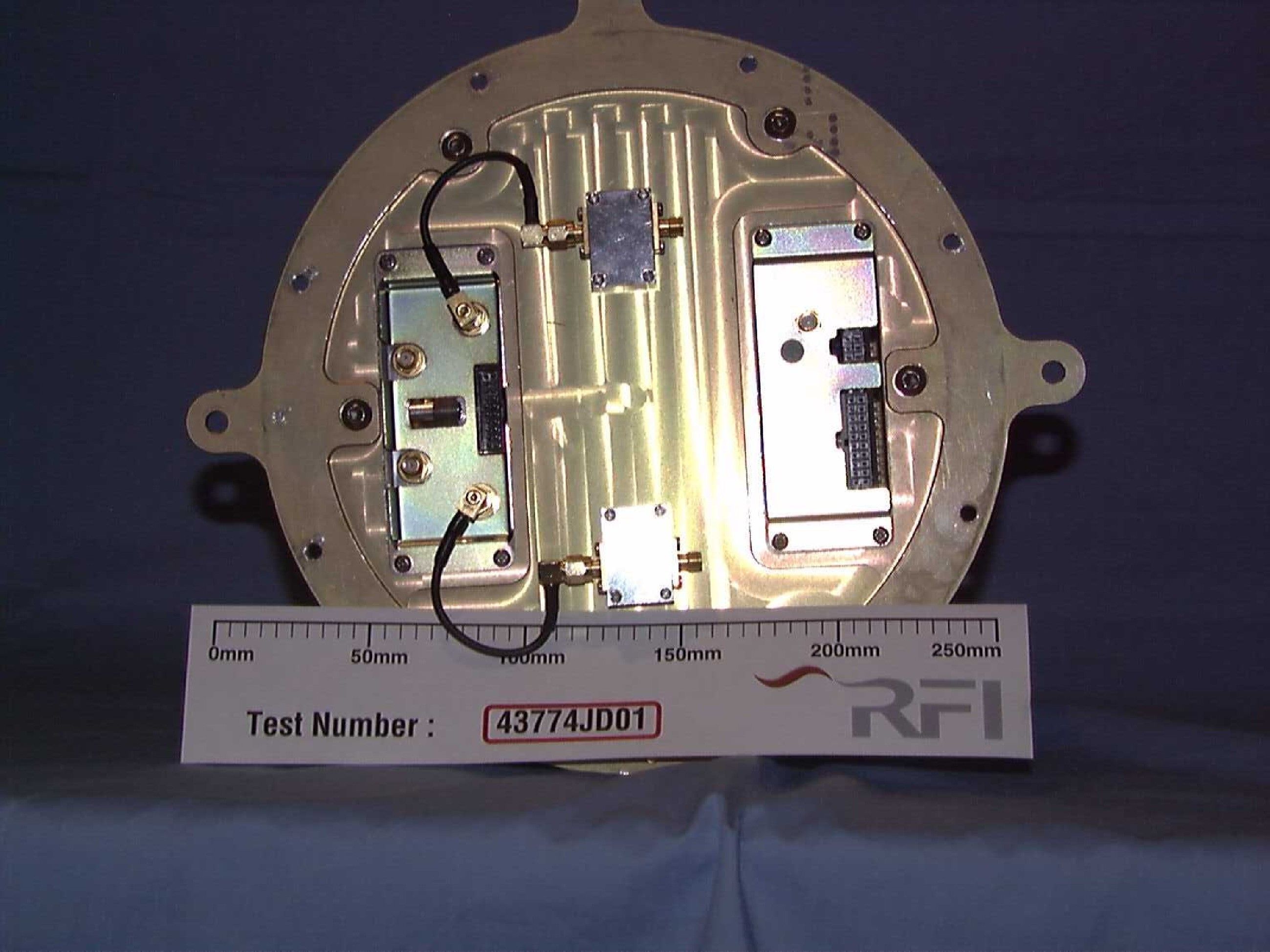

Document Text
Text extracted from the exhibit documents filed with the FCC. Open a document above to read the original.
Users Manual
Copyright Copyright © 2002 Radiant Networks. All rights reserved. The contents of this document and associated computer programs are copyright and may not be reproduced or used in any form or by any means without the prior written permission of Radiant Networks. Trademarks and acknowledgements Radiant Networks TM , MESHWORKS TM and the Radiant logo (shown at the bottom of this page) are trademarks of Radiant Networks. Marconi is a trademark of Marconi Corporation plc. Sun and Java are trademarks of Sun Microsystems, Inc. Disclaimer Radiant Networks reserves the right to make changes without notice at any time to this document, and shall not be held legally responsible for any typographical, arithmetic and listing errors. Draft status notice This is a draft document circulated internally for review and comment. This manual has been prepared for use by Radiant Networks personnel, licensees and customers. 25/6/2002 Contents Page i Contents Introduction ........................................................................................ 1 Unpacking the shipment .................................................................. 1 Safety ............................................................................................................. 3 General safety recommendations and practices .............................. 4 General safety considerations .......................................................... 4 Other safety considerations .............................................................. 5 Electrical safety .................................................................................... 5 Fibre optic safety .................................................................................. 5 Radio safety .......................................................................................... 6 Node overview ............................................................................................... 7 Overview of a node ............................................................................. 8 MESHWORKS Outdoor Unit .......................................................... 8 MESHWORKS Indoor Unit ............................................................ 9 MESHWORKS Uninterruptible Power Supply ............................. 10 An example of a basic node ............................................................. 11 Installation .................................................................................................. 13 Mechanical installation .................................................................... 14 ODU installation ............................................................................... 15 Required tools and equipment ....................................................... 15 Use of a Craft Terminal during installation ................................... 16 ODU equipment components ......................................................... 17 ODU weight and dimensions .............................................................. 19 ODU ............................................................................................ 19 ODU bracket assembly ............................................................... 19 Interfaces and connections .................................................................. 19 ODU siting ..................................................................................... 20 MESHWORKS customer node installationPage ii Draft copy Lightning protection ....................................................................... 22 Mounting specifications ..................................................................... 22 Mounting procedure ........................................................................... 23 Getting the correct vertical alignment ........................................ 23 Getting the correct directional alignment ................................... 25 Attaching the ODU to its bracket ............................................... 25 Commissioning the ODU ............................................................... 28 UPS installation ................................................................................ 34 UPS weight and dimensions ............................................................... 35 Required tools and equipment ........................................................ 35 Safety precautions for the UPS ...................................................... 35 Installation procedure ..................................................................... 36 Rack mounting of UPS .................................................................. 40 Replacing the fuse .......................................................................... 40 IDU installation ................................................................................. 42 Required tools and equipment ........................................................ 42 Desk or floor mounting ...................................................................... 42 Rack mounting ................................................................................... 42 Equipment components .................................................................. 43 Horizontal mounting .......................................................................... 43 Standard 19” rack mounting option ............................................ 43 Vertical mounting ............................................................................... 44 Short floor standing case ............................................................ 44 Long floor standing case ............................................................ 44 End pieces for IDU ............................................................................. 45 IDU end cap ................................................................................ 45 IDU base ....................................................................................…
Text truncated - open the document above for the full version.
Users Manual
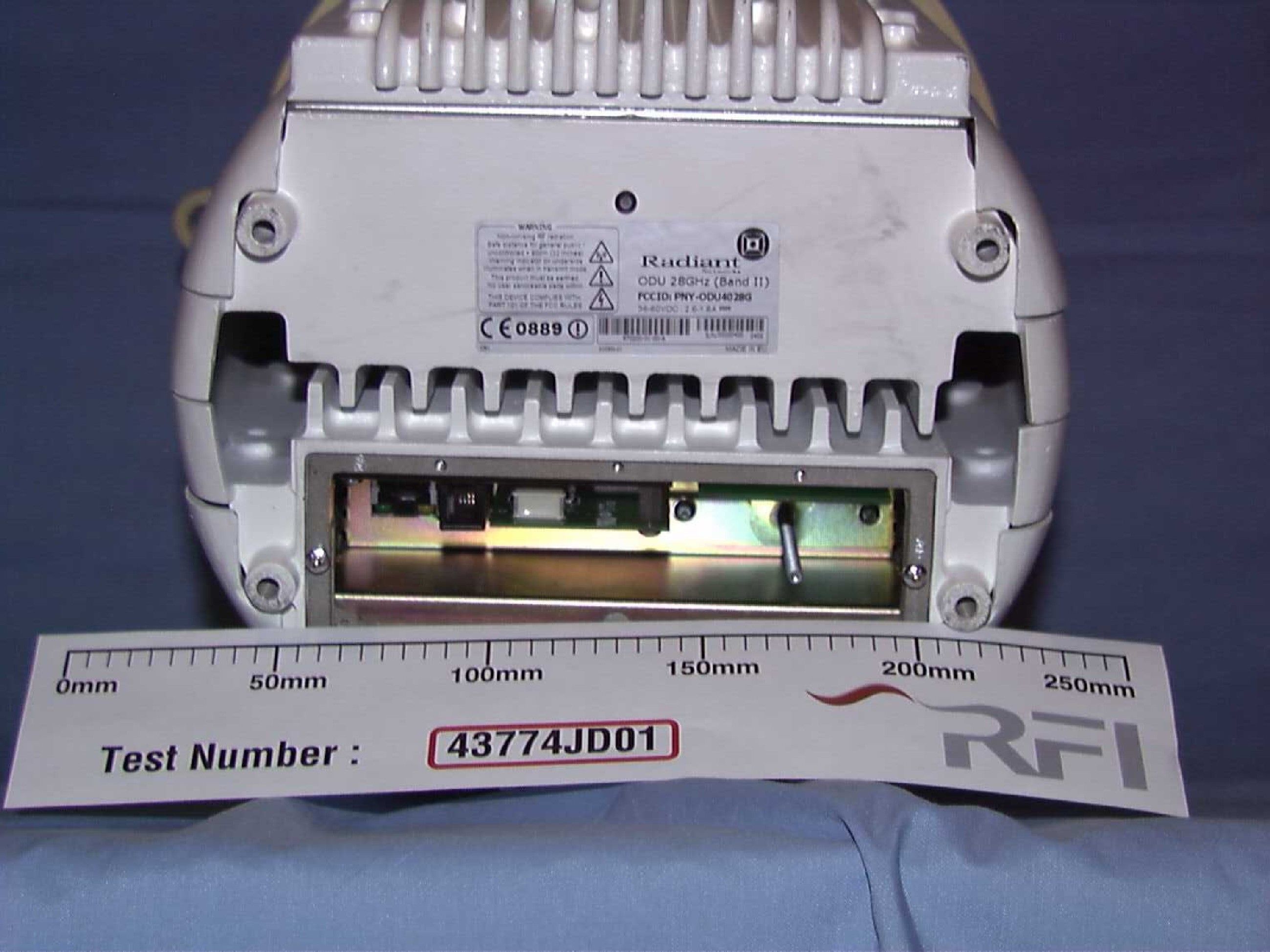
ODU kit Check the contents list before you proceed with assembly. This pack contains the following items: ODU Large metal gland nut (1) and small plastic gland nuts (2) RJ45 plug and a 6-way AMP power connector Plastic spike or bung for tip of ODU 1. Assemble and mount the ODU collar on the metal pole (see instructions for that kit). 2. On the ODU collar, adjust the jacking screws to the appropriate heights for correct vertical mounting of the ODU. Lock the jacking screws in position with the M10 Nyloc nuts. 3. If required, fit the multimode fibre module in the ODU (see instructions for that kit). 4. Mount the ODU on the collar, and secure it in place with the M6 x 20mm socket cap head screws and spherical seated washers (diagram 1). 5. Unscrew the gland plate from the underside of the ODU, and put all the wiring in place (see diagram 2). An RJ45 plug and a power connector are provided. See wiring diagrams on next page. 6. Taking care not to damage the GPS aerial in the cap, push the plastic spike or bung into the hole on the tip of the ODU (diagram 3). Parts list Assembly instructions ODU 1 3 2 ODU spike ODU bung Spherical seated washer set M6 x 20 mm socket cap head screws Close-up detail M10 Nyloc nuts Jacking screws Do not attempt to install or power up the ODU if the temperature is below -20 Celsius (-4 Fahrenheit).°° Pin 1 Pin 6 Interior layout of the ODU’s compartment IDU (ATM25) connector Craft Terminal connector Power connector Multi mode fibre module GPS module EUN0005 Ver 1.1 IDU pinouts ODU pinouts RJ45 connectorRJ45 connector Pin 1 Pin 8 Pin 1 Pin 8 Pinouts for ODU power supply Pinouts for data cable between ODU and IDU The following diagram illustrates the pinouts for the power cable connections between the ODU and the UPS: The connector at the ODU end is a right angle 6-way 0.2” Weidmuller or Wago type with friction lock. lease refer to the installation instructions for the UPS. The following diagram illustrates the pinouts for the data cable connections between the ODU and the IDU: The connectors at both ends are RJ45 type connectors. This uses a straight through, one-to-one wiring. For further details, p 0V 0V -48 V -48 V Mains AC fail Charger fail Common Low battery UPS pinouts ODU pinouts Green White Brown Red Blue Black Pin 6 - Chassis ground Pin 5 - Charger fail Pin 4 - Low battery Pin 3 - Mains AC fail Pin2-48Vnegative Pin1-48Vpositive
Users Manual
Copyright Copyright © 2002 Radiant Networks. All rights reserved. The contents of this document and associated computer programs are copyright and may not be reproduced or used in any form or by any means without the prior written permission of Radiant Networks. Trademarks and acknowledgements Radiant Networks TM , MESHWORKS TM and the Radiant logo (shown at the bottom of this page) are trademarks of Radiant Networks. Disclaimer Radiant Networks reserves the right to make changes without notice at any time to this document, and shall not be held legally responsible for any typographical, arithmetic and listing errors. Draft status notice This is a draft document circulated internally for review and comment. This manual has been prepared for use by Radiant Networks personnel, licensees and customers. EUD0006 Ver 1.0 24/7/2002 Page iContents Contents Introduction .......................................................................................1 General safety notes .....................................................................................3 Warnings and cautions .....................................................................4 Warnings .............................................................................................4 Cautions ...............................................................................................5 Labels on Mesh components ...............................................................5 Safety standards ................................................................................6 Standards .............................................................................................6 Optical safety .....................................................................................7 Working with lasers .............................................................................7 Working with optical fibre cables .......................................................7 Precautions against risk of injury .......................................................7 Precautions against damage to equipment ..........................................8 Handling & transport ..................................................................................9 Manual handling ...............................................................................10 Good handling technique .....................................................................10 Assess the situation .............................................................................10 Position your feet ................................................................................10 Adopt a good posture ..........................................................................10 Get a firm grip ....................................................................................10 Keep close to the load .........................................................................10 Jerk-free movements ...........................................................................11 Move your feet ....................................................................................11 Put down, then adjust ..........................................................................11 Further reading ....................................................................................11 Environmental considerations .........................................................12 MESHWORKS safety guidePage ii Packaging ........................................................................................... 12 General environmental operating conditions ..................................... 12 MESHWORKS outdoor equipment ................................................... 12 MESHWORKS indoor equipment ..................................................... 13 Safe environmental disposal ............................................................... 13 Reference ..................................................................................................... 15 Glossary of terms .............................................................................. 16 Radiant contact details ..................................................................... 18 Page 1Introduction Introduction This document draws attention to the hazards and risks involved when handling, installing and commissioning MESHWORKS Broadband Wireless Access telecommunications and electrical equipment. Regular reference to this document is recommended to ensure that employees and contractors remain familiar with the identified hazards, risks and detailed general precautions. This document however, is not a substitute for the adoption of safe working systems, adequate training, competency and supervision (required by legislation, or organisations employing personnel to carry out the activities concerned). It is essential that any personnel working directly on MESHWORKS equipment fulfil the following criteria: !They should be competent, adequately trained and qualified to carry out the tasks required. !They should be authorised to carry out the tasks required. !They should be fully conversant with, and follow the specific safety guidelines relating to MESHWORKS equipment and the general safety procedures and safe systems of work of their company. !They should always read and follow the warnings and cautions before starting work on any equipment. MESHWORKS documents provide written procedures, which state the precautions to be taken to ensure health and safety during the installation and commissioning of MESHWORKS equipment. At appropriate places in the documentation, safety procedures, warning and caution notices are detailed relating to specific activities to alert employees and contractors to potentially hazardous situations. Documentation also draws attention to the requirement for those installing and commissioning MESHWORKS equipment to refer to safety procedures and safe systems of work, established by their own companies. Y…
Text truncated - open the document above for the full version.
Block Diagram
FIFO BUFFER RRC FILTER COMPLEX EQUALISER SYMBOL SLICER Phase/Cartesian Look-Up Ampl. Tracking Loop TxRx_IF PCB DAC FPGA ADC Differential Driver FPGA FPGA Receiver Transmitter SAW ×14 DACFPGA SYNTHESISER ADC FPGA SAW BCH DECODE DSP Gain Control Timing Ant. Servo Exploration Link Form./modify Equaliser Training ATM INTERFACE RS DECODE BURST SLICER MOTOR SERVO FRAME SEQUENCER BURST FORMATTER BCH ENCODE RS ENCODE HOST INTERFACE RADIO INTERFACE COMPLEX SYMBOL FORMATION CORRELATOR COEFFICIENT STORE MODEM IF PROCESSOR & SYNTHESISER CONTROL & TLM BIAS REGS X2 CONTROL & TLM BIAS REGS X2 NODE CONTROLLER ATM155ATM25 mmW TRM 2 mmW TRM 1 ELECTRONIC POWER CONDITIONER FROM UPS MESH NETWORK NODE OUTDOOR UNIT BLOCK DIAGRAM MODEM INTERFACE DRUM MOTORS DAC ADC CLK 35 MHz LO2 3591 MHz 479.5 MHz 4070.5 MHz LO3 444.5 MHz LO1 11746 to 12684 MHz Fc 27.5624 to 29.4385 GHz 35 MHz 479.5 MHz 4070.5 MHz 56 MHz 10 MHz GPS MODULE
ID Label/Location Info
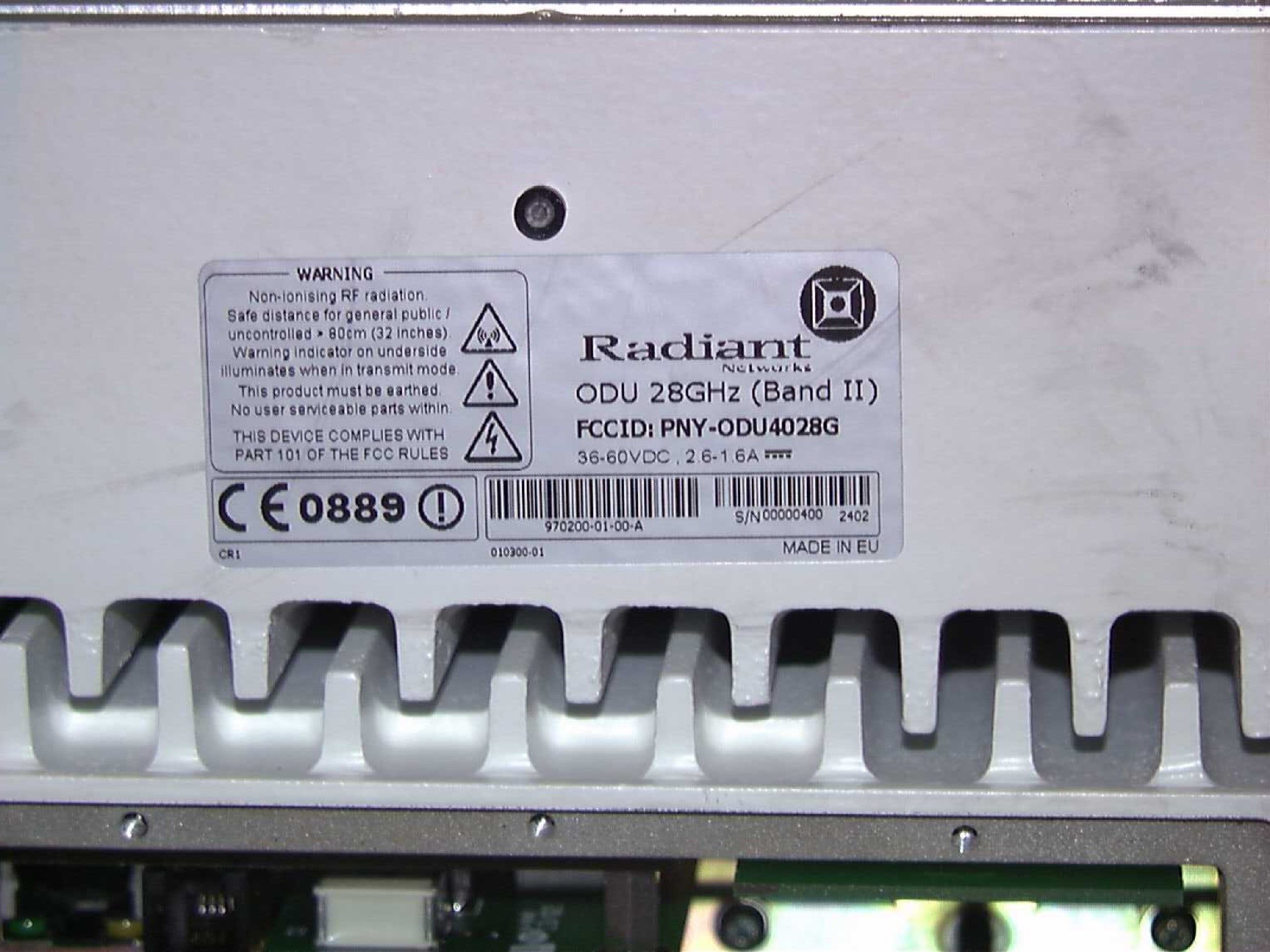
CONFIDENTIAL Page 1 of 1 Copyright © 2002 Radiant Networks plc. All rights reserved ODU Label Information Author/Editor: Andrew F Hare Status: Issue 1 Date: 2 August 2002 END OF DOCUMENT Assembly Issue Mod Site Part No. State Code
Operational Description
Meshworks System Description - 1-20.doc Page 1 of 55 Copyright © 2001 Radiant Networks plc. All rights reserved 10/08/01 Radiant™ MESHWORKS™ System Description Author/Editor: Sally Chang Status: Issue 1.20 Date: 10/08/01 Radiant Networks PLC The Mansion Chesterford Park Little Chesterford Essex CB10 1XL U.K. Tel: +44 (0) 1799 533 600 Fax: +44 (0) 1799 533 634 [email protected] www.radiantnetworks.com Meshworks System Description - 1-20.doc Page 2 of 55 Copyright © 2001 Radiant Networks plc. All rights reserved 10/08/01 System Description Version Author Date Comments 1.10 TRF 11/7/01 First draft for comment only 1.11 SLC 5/8/01 Updated 1.20 SLC 10/08/01 Issued Following Review Important Notice This document contains preliminary information. Information, data and figures are subject to change without notice. This document is a system overview and is not intended to represent a system specification While we have endeavoured to ensure that the contents of this document are as accurate as possible, Radiant Networks take no liability for any errors or omissions within this document. The ongoing development of our products and systems means that we reserve the right to update documents at any time. The copyright for this document resides with Radiant Networks PLC. Reproduction in part or whole is prohibited without the express permission of Radiant Networks PLC. This document may contain Registered Trademarks. Meshworks System Description - 1-20.doc Page 3 of 55 Copyright © 2001 Radiant Networks plc. All rights reserved 10/08/01 System Description CONTENTS 1 INTRODUCTION...................................................................................................................6 1.1 OVERVIEW................................................................................................................................................................6 1.2 KEY BENEFITS OF MESHWORKS™....................................................................................................................6 1.3 THE MARKET CHALLENGE.....................................................................................................................................7 1.4 BROADBAND ACCESS NETWORKS..........................................................................................................................7 1.5 WIRELESS ACCESS NETWORKS..............................................................................................................................8 1.5.1 Financial attraction of wireless access......................................................................................................8 1.5.2 Problems with the use of wireless access for broadband.......................................................................8 1.6 MESHWORKS™ - A REVOLUTION IN THINKING FOR BROADBAND RADIO ACCESS..................................10 2 MESHWORKS™ SYSTEM ARCHITECTURE.....................................................................11 2.1 OVERVIEW..............................................................................................................................................................11 2.1.1 Mesh – The New Paradigm........................................................................................................................11 2.1.2 How Does Mesh Deliver Improved Coverage?......................................................................................12 2.1.3 How Does Mesh Deliver Greater Performance?...................................................................................12 2.1.4 How Does Mesh Deliver Economic Advantage?....................................................................................12 2.2 THE RADIANT NODE.............................................................................................................................................13 2.2.1 Node Overview.............................................................................................................................................13 2.2.2 The Outdoor Unit (ODU)...........................................................................................................................14 2.2.3 The Indoor Unit (IDU)................................................................................................................................17 2.2.4 The Uninterruptible Power Supply (UPS)...............................................................................................18 2.2.5 Other Node Elements..................................................................................................................................18 2.3 RADIANT MESH SYSTEM ARCHITECTURE.........................................................................................................19 2.3.1 Radiant Edge Switching System (RESS)..................................................................................................20 2.3.2 System Nodes................................................................................................................................................20 2.3.3 Customer Nodes...........................................................................................................................................22 2.3.4 Visibility requirements................................................................................................................................23 3 MESHWORKS™ SERVICES AND INTERFACES................................................................24 3.1 SUPPORTED INTERFACES......................................................................................................................................24 3.1.1 Customer Interface......................................................................................................................................24 3.1.2 Core Network Interface.............................................................................................................…
Text truncated - open the document above for the full version.
Operational Description
ODU Operational Description 2.1.doc CONFIDENTIAL Page 1 of 28 Copyright © 2002 Radiant Networks plc. All rights reserved Radiant Broadband Wireless Access Network Radiant Networks MESHWORKSô Outdoor Unit – Operational Description Author/Editor: Andrew F Hare Status: Issue 2.1 Date: 15 August 2002 Approvals Name Title Signature Peter Hudson SITaR Manager Radiant Networks PLC The Mansion Chesterford Park Little Chesterford Essex CB10 1XL U.K. Tel: +44 (0) 1799 533 600 Fax: +44 (0) 1799 533 601 ODU Operational Description 2.1.doc CONFIDENTIAL Page 2 of 28 Copyright © 2002 Radiant Networks plc. All rights reserved ODU Operational Description Version Author Date Comments 1.0 A F Hare 9-Aug-02 Contents previously issued in separate docs. 2.0 A F Hare 12-Aug-02 Synthesizer section updated 2.1 A F Hare 15-Aug-02 Channel list re-formatted (see Sec 1.4) Whilst we have endeavoured to ensure that the contents of this document are as accurate as possible, Radiant Networks take no liability for any errors or omissions within this document. The ongoing development of our products and systems means that we reserve the right to update these documents at any time. The copyright for this document resides with Radiant Networks PLC. Reproduction in part or whole is prohibited without the express permission of Radiant Networks PLC. This document may contain Registered Trademarks. ODU Operational Description 2.1.doc CONFIDENTIAL Page 3 of 28 Copyright © 2002 Radiant Networks plc. All rights reserved ODU Operational Description CONTENTS 1 INTRODUCTION.................................................................................................................. 4 1.1 SCOPE......................................................................................................................................................4 1.2 NODE CONTROLLER.................................................................................................................................7 1.2.1 ATM Switch .....................................................................................................................................8 1.2.2 Boot NVRAM...................................................................................................................................8 1.2.3 ATM RAM .......................................................................................................................................8 1.2.4 Main NVRAM ..................................................................................................................................8 1.2.5 RAM ................................................................................................................................................8 1.2.6 Local PSU .......................................................................................................................................8 1.2.7 UPS AS ............................................................................................................................................9 1.2.8 I2C...................................................................................................................................................9 1.2.9 NV file .............................................................................................................................................9 1.2.10 INT ..................................................................................................................................................9 1.2.11 <MP_SAP>.....................................................................................................................................9 1.2.12 H/W Boot Port.................................................................................................................................9 1.2.13 Reset Control...................................................................................................................................9 1.2.14 Clock Generation ..........................................................................................................................10 1.2.15 Craft Interface ...............................................................................................................................10 1.2.16 UART1/2........................................................................................................................................10 1.2.17 Flag port .......................................................................................................................................10 1.2.18 155 UTP PHY................................................................................................................................10 1.3 IF PROCESSOR.......................................................................................................................................11 1.3.1 Transmit IF Up-Converter ............................................................................................................11 1.3.2 Second Conversion........................................................................................................................13 1.3.3 Passband Response .......................................................................................................................13 1.3.4 Total strip ......................................................................................................................................14 1.3.5 Output power.................................................................................................................................14 1.4 SYNTHESIZER.........................................................................................................................................15 1.5 MODEM..................................................................................................................................................18 1.6 DC POWER BOARD ñ THE ELECTRONIC POWER CONDITIONER (EPC) .…
Text truncated - open the document above for the full version.
Operational Description
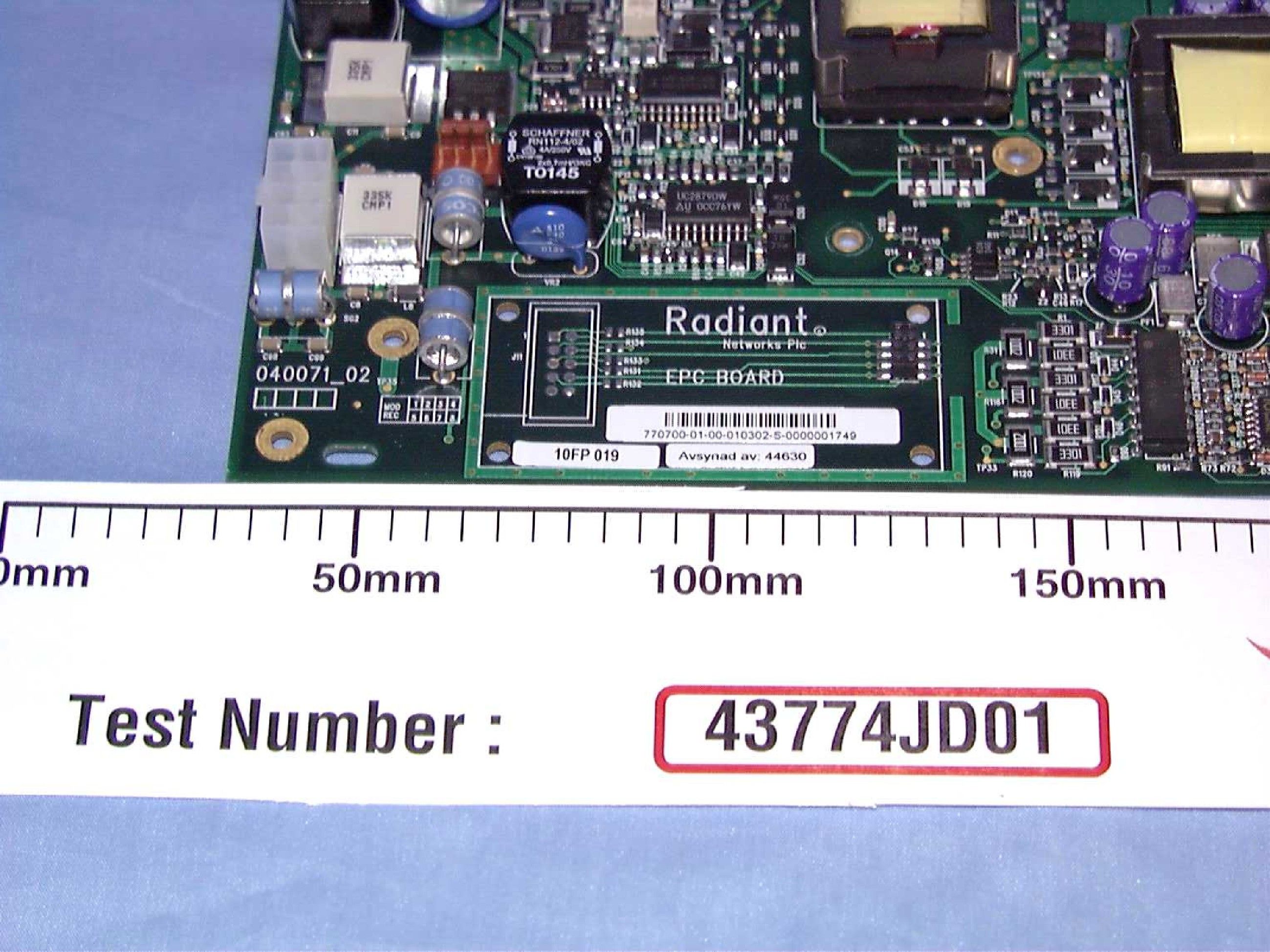
Range of Operating Pow er -12 to +18 dBm co ntrolled by firmware which adjusts attenuator settings, see Operational Description. DC Voltages The DC voltages and currents are as detailed in the Operational Descriptio n Section 1.6 and set up as per the Tune Up Procedure.
Parts List/Tune Up Info
770500-07.doc CONFIDENTIAL Page 1 of 35 Copyright © 2001 Radiant Networks plc. All rights reserved 05/08/02 Radiant Broadband Wireless Access Network Production Test Specification for Synthesiser (Band II) Boards Assembly Part Numbers: 770500 (To latest BOM revision) Author/Editor: John Molloy Status: 7.0 Release Date: 05/08/02 Pre-release Document Filename: SynthesizerTestSpec_Q_0410 Approvals Name Title Signature P Hudson SITaR Dev’ Manager E Bayer Radio Systems Dev’ Manager K Bridge Integration Team Leader J Molloy Senior RF Design Engineer Radiant Networks PLC The Mansion Chesterford Park Little Chesterford Essex CB10 1XL U.K Tel: +44 (0) 1799 533 600 Fax: +44 (0) 1799 533 601 770500-07.doc CONFIDENTIAL Page 2 of 35 Copyright © 2001 Radiant Networks plc. All rights reserved 05/08/02 Version Author Date Comments Draft H JWM 08/05/01 Draft for comments Draft J JWM 22/05/01 Draft updates Draft K JWM 04/06/01 Draft updates Draft L JWM 28/06/01 Draft updates Draft M JWM 05/07/01 Change to para 4.3.6 Draft N JWM 05/09/01 Change to para 4.2.3 & 4.2.4 Draft O JWM 07/09/01 Change to para 4.3.1 Draft P JWM 25/09/01 Changes associated with U29 & U78 Digital Potentiometers addition & miscellaneous limit changes Draft Q JWM 04/10/01 Changes to para 4.1.4, 4.3.1, 4.3.6, 4.7.1 and 4.7.2 1.0 MM 23/11/01 Document renamed for Production Release 2.0 JWM 11/01/02 ECN No. 172 Section 4.7 & 6 change 3.0 JWM 29/01/02 Updates after review 4.0 JWM 21/02/02 Change of Synthesiser Calibration Data in para 1.1.6 5.0 JWM 18/04/02 Change of Synthesiser Calibration Data in para 1.1.6 6.0 JWM 23/04/02 Change of Synthesiser Calibration Data in para 1.1.6 ‘VCO Sensitivity’ 7.0 JWM 24/07/02 Changes to Table 9 & 12 and para 4.7 and addition of section 5 Change History: Page No. Change Detail 18 & 27 Output Power Level requirements changed. 10 & 11 Synth Cal. data : Channel Spacing; Start/Stop Freq & VCO Sensitivity 10 & 11 Synth Cal. Data: VCO Sensitivity 21 Output Power measurement details 28 Remove 100MHz offset measurement 18 Improve –8Volt supply tol. with respect to current drawn. 24 Add Fault Finding Section Whilst we have endeavoured to ensure that the contents of this documen…
Text truncated - open the document above for the full version.
Contact Information
Applicant
Andrew F Hare(Senior Integration Engineer)
Technical Contact
Radiant Networks PlcAndrew F Hare
[email protected]+441799533741
The Mansion · Little Chesterford , Essex · United Kingdom
Test Firm
RFI Global Services Ltd.Allan Hume
Technical Specifications
| # | Rule Parts | Frequency Range | Power Output | Emission | Tolerance |
|---|---|---|---|---|---|
| 1 | 101 | 27.50 GHz - 28.35 GHz | 63.00 mW | 23M0V7W | 0.0010000000 % |