PO3WNGWAP104Pear Wireless Series 100 Wall Access Point
Galtronics USA Inc.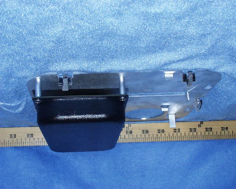
Click to zoom
Application Details
- Equipment Class
- DSS - Part 15 Spread Spectrum Transmitter
- Date of Grant
- Dec 26, 2001
- Application Purpose
- Original Equipment
- Date of Application
- Dec 26, 2001
- Equipment Note
- Pear Wireless Series 100 Wall Access Point
- Frequency Range
- 2412.00000000 - 2462.00000000
- Company
- Galtronics USA Inc.
- Country
- United States
Documents & Files
Document Text
Text extracted from the exhibit documents filed with the FCC. Open a document above to read the original.
Users Manual
COPYRIGHT STATEMENT No part of this publication may be reproduced, stored in a retrieval system, or transmitted in any form or by any means, whether electronic, mechanical, photocopying, recording, or otherwise without the prior written Approval of the publisher. Printed in USA, December 2001 Pear Wireless Wall Access Point December 2001 SAFETY This equipment is designed with the utmost care for the safety of those who install and use it. However, special attention must be paid to the dangers of electrical shock and static electricity when working with electrical equipment. All guidelines of this manual and of the computer manufacturer must be followed at all times to ensure the safe use of the equipment. LIMITATION OF LIABILITY THE LIABILITY OF GALTRONICS USA, INC. AND ITS AFFILIATES SHALL, UNDER ALL CIRCUMSTANCES, BE LIMITED TO THE AMOUNT PAID FOR THE PEAR WIRELESS PRODUCTS AND EQUIPMENT. GALTRONICS SHALL IN NO EVENT BE LIABLE FOR DIRECT, SPECIAL, INCIDENTAL, PUNITIVE OR CONSEQUENTIAL DAMAGES, INCLUDING BUT NOT LIMITED TO DAMAGE TO PROPERTY, INCONVENIENCE, LOSS OF GOODWILL, LOST PROFITS OR REVENUE, LOSS OF USE OF THE PRODUCTS OR ANY ASSOCIATED EQUIPMENT, COST OF SUBSTITUTE EQUIPMENT, DOWNTIME COSTS, OR CLAIMS OF ANY PARTY DEALING WITH PURCHASER FOR SUCH DAMAGES, CAUSED BY ANY DEFECTS IN THE PEAR WIRELESS PRODUCTS OR EQUIPMENT OR AS A RESULT OF USE OF THE PEAR WIRELESS PRODUCTS OR EQUIPMENT UNDER ANY LEGAL OR EQUITABLE THEORY, EVEN IF GALTRONICS USA, INC. HAS BEEN ADVISED OF THE POSSIBILITY OF SUCH DAMAGES. STATEMENT OF CONDITIONS The information contained in this manual is subject to change without notice. Pear Wireless shall not be liable for errors contained herein or for incidental or consequential damages in connection with the furnishing, performance, or use of this manual or equipment supplied with it. TRADEMARKS AND LICENSES Pear, Pear Wireless, Pear Wireless Network, and Pear-to-Pear Wireless Network are trademarks of Galtronics USA, Inc. Other product and company names are trademarks or registered trademarks of their respective holders. Pear Wireless™ Pear Wireless™ Technical Support 4645 East Cotton Center Boulevard www.pearwireless.com Building Two [email protected] Phoenix, AZ 85040 USA +1 (866) 772-5285 +1 (602) 659-3000 Except for the End-User Software License granted for use of the Pear Wireless Software, nothing in this User Manual shall be construed as a grant of or as an intention or commitment to grant any rights, title or interest, of any nature whatsoever, including but not limited to a license, implied or otherwise, in the Pear Wireless Products or equipment, intellectual property rights or any processes encompassed thereby or any improvements or developments thereon of Galtronics USA, Inc. or its affiliates. All Pear Wireless Products and equipment, intellectual property rights and any processes encompassed thereby and any improvements or developments thereon shall remain the sole and exclusive property of Galtronics USA, Inc. WARRANTY INFORMATION Galtronics USA, Inc. warrants the Pear Wireless Products and equipment to consumers only as set forth in the Galtronics Limited Warranty accompanying such products. EXCEPT FOR THE GALTRONICS LIMITED WARRANTY ACCOMPANYING THE PEAR WIRELESS PRODUCTS AND EQUIPMENT AND TO THE FULL EXTENT PERMITTED BY LAW, GALTRONICS MAKES NO WARRANTY, EXPRESS OR IMPLIED, WITH RESPECT TO THE PRODUCTS. IN PARTICULAR, GALTRONICS MAKES NO WARRANTY RESPECTING THE MERCHANTABILITY OR QUALITY OF THE PRODUCTS OR THEIR SUITABILITY OR FITNESS FOR ANY PARTICULAR PURPOSE OR USE OR RESPECTING TITLE OR INFRINGEMENT AND, TO THE FULL EXTENT PERMITTED BY LAW, GALTRONICS PROVIDES THE PRODUCTS AS-IS. THE ENTIRE RISK AS TO THE QUALITY, SELECTION AND PERFORMANCE OF THE PRODUCT IS WITH THE PURCHASER OF THE PRODUCT. Complete warranty information for all Pear Wireless products is available online at www.pearwireless.com. REGULATORY INFORMATION Federal Communications Commission (FCC) This equipment has been tested and found to comply with the limits for a Class B digital device, pursuant to Part 15 of the FCC Rules. These limits are designed to provide reasonable protection against harmful interference in a residential installation. This equipment generates, uses, and can radiate radio frequency energy and, if not installed and used in accordance with the instructions, may cause harmful interference to radio communications. However, there is no guarantee that interference will not occur in a particular installation. If this equipment does cause harmful interference to radio or television reception, which can be determined by turning the equipment off and on, the user is encouraged to try to correct the interference by one of the following measures: • Reorient or relocate the receiving antenna. • Increase the separation between the equipment and the receiver. • Plug the equipment into an outlet on a circuit different from that to which the receiver is connected. • Consult the dealer or an experienced radio/TV technician for help. The user is cautioned that any changes or modifications not expressly Approved by the party responsible for compliance could void the user's authority to operate this equipment. This device complies with Part 15 of the FCC Rules. Operation is subject to the following two conditions: (1) this device may not cause harmful interference, and (2) this device must accept any interference received, including interference that may cause undesired operation. Industry Canada (IC) This class B digital Apparatus meets all requirements of the Canadian Interference Causing Equipment Regulations. Responsible Party Galtronics 4645 East Cotton Center Boulevard Telephone: +1 (602) 659-3000 Building Two Fax: +1 (602) 453-0259 Phoenix, AZ 85040 USA Email: [email protected] STATEMENT OF CONDITIONS The information contained in this User Manual is subject to change without notice. While the information furnished is believed to be accurate and rel…
Text truncated - open the document above for the full version.
Block Diagram
WX-1500 Block Diagram ANT SW WEPENGINE 2.4GHz BPF TX/RX SW MIXER SAW FILTER AGC CTL LNA TX/RX SW PLL 2038-2098M Hz AMP MIXER AMP AMP AMP TX/RX SW MIXE R MIXER AMP MIXE R MIXER LO AMP PLL Q DAC TX DAC TX ADC Q ADC I ADCI DAC RF DAC RF ADC IF DAC DEMODULATOR I/O MODULATOR TX ALC HOST INTERFAC E CONTROL PROCESSOR MEMORY ACCESS ARBITER GP SERIAL PORTS FLASH MEMORY RADIO CONTROL] PORTS RADIODATAINTERFACE SRAM MEMORY CPU 44MHz XTAL OSC 2.4GHz VCO 748MHz VCO U11 RF/IF CONV U9 QUAD IF CONV U5 BASEBAND PROCESSOR U3 CPU FL1 U6 XTAL OSC 374 MHz saw filter FL4 BPF U10 ANT SW U14 RF VCO U13 IF VCO REG3.3V VSS REG3.3V 5V AMP BPF FL5 U12 POWER AMP U18U19 U4,U1 MEMORY U2 MEMORY RXI RXQ TXI TXQ DATA TX/RX 2412-2472 MHz ETHERNET control RJ45 interface POWER jet U250 J250
Cover Letter(s)
From: Denise Teng Sent: Thursday, December 27, 2001 3:25 PM To: Mike Kuo Subject: RE: GALTRONICS, FCC ID:PO3WNGWAP104, AN01T1689 Mike, Q3: Please see attachment for MPE calculation. regards, Denise -----Original Message----- From: CERTADM Sent: Friday, December 07, 2001 5:38 PM To: '[email protected]' Subject: GALTRONICS, FCC ID:PO3WNGWAP104, AN01T1689 Notice_content ------------- Question #1: Please provide Processing Gain Data. Question #2: The antenna gain listed in the technical specifiction and user manual is 1dBi gain. However, in the antenna specification file, the antenna gain is listed as 8dBi gain. Please explain. Question #3: Please provide MPE calculation. Question #4: What is the theoretical process gain? Chip/bit rate? Spread rate/data rate? Best Regards Mike Kuo / TCB Certifier The items indicated above must be submitted before processing can continue on the above referenced application. Failure to provide the requested information within 60 days of the original e-mail date may result in application dismissal and forfeiture of the filing fee. Also, please note that partial responses increase processing time and should not be submitted. Any questions about the content of this correspondence should be directed to the e-mail address listed below the name of the sender.
ID Label/Location Info
PROPOSED FCC ID LABEL AND LOCATION FCC ID LABEL GALTRONICS This device complies with Part 15 of FCC rules. FCC ID: PO3WNGWAP104
Parts List/Tune Up Info
Antenna Specification for Galtronics Wireless Access Point WNG-WAP-104 Antenna system: - Dual antenna diversity system - Internal Double-Folded Dipole Antennas - Peak Gain 8 dBi
RF Exposure Info
For 1 dBi antenna For 8 dBi antenna MPE CALCULATION for GALTRONICS WNG-WAP-104 Formular used in the MPE Calculations: E^2/3770 = S, mW/cm2 Pwatts*Ggain = 10^(PdBm-30+GdBi)/10) E, V/m = (Pwatts*Ggain*30)^.5/d, meters d = ((Pwatts*G*30)/3770*S))^0.5 --------- (A) Since S (mW/cm 2 ) = 1.00from 1.1310 Table 1 P (dBm) = 20.7EUT output power G (dBi) = 8.0EUT antenna gain Substitute these parameters into the A above, we have MPE safe distance d (cm) =7.7 NOTE: For mobile or fixed location transmitters, minimum separation distance is 20 cm, even if calculations indicate MPE distance is less Form ular used in the M PE Calculations: E^2/3770 = S, mW/cm2 Pw atts*G g a in = 10^(PdBm -30+G dBi)/10) E, V/m = (Pw a tts*G g a in*30)^.5/d, meters d = ((Pw a tts*G *30)/3770*S))^0.5 --------- (A ) Since S (mW/cm 2 ) = 1.00 from 1.1310 Table 1 P (d B m ) = 20.7 EUT output power G (d B i) =1.0 EUT antenna gain Sub stitute these param eters into the A above, we have 3.4 MPE sa fe distance d (c m ) = M PE CALCULATION for GALTRONICS WNG-WAP-104 NOTE: Fo r mobile or fixed location transm itters, minimum separation distance is 20 cm , even if calculations indicate M PE distance is less
Test Report
FCC CFR47 PART 15 CERTIFICATION TEST REPORT FOR 2.4GHz DIRECT SEQUENCE SPREAD SPECTRUM WIRELESS NETWORKING ACCESS POINT MODEL: WNG-WAP-104 FCC ID: PO3WNGWAP104 REPORT NUMBER: 01U1031-1 ISSUE DATE: NOVEMBER 14, 2001 Prepared for GALTRONICS USA INC. 4645 E. COTTON CENTER BLVD., BLDG 2 PHOENIX, AZ 85040 USA Prepared by COMPLIANCE CERTIFICATION SERVICES 561 F MONTEREY ROAD MORGAN HILL, CA 95037, USA TEL: (408) 463-0885 FAX: (408) 463-0888 REPORT NO: 01U1031-1 FCC ID: PO3WNGWAP104 DATE: November 14, 2001 EUT: 2.4 GHz Direct Sequence Spread Spectrum Wireless Network Access Point Page 2 of 54 COMPLIANCE CERTIFICATION SERVICES DOCUMENT NO: CCSUP4031A 561F MONTEREY ROAD, MORGAN HILL, CA 95037 USA TEL: (408) 463-0885 FAX: (408) 463-0888 This report shall not be reproduced except in full, without the written approval of CCS. This document may be altered or revised by Compliance Certification Services personnel only, and shall be noted in the revision section of the document. TABLE OF CONTENT 1. TEST RESULT CERTIFICATION-----------------------------------------------------------------------------------------------------3 2. EUT DESCRIPTION----------------------------------------------------------------------------------------------------------------------4 3. TEST METHODOLOGY-----------------------------------------------------------------------------------------------------------------4 4. TEST FACILITY---------------------------------------------------------------------------------------------------------------------------4 5. ACCREDITATION AND LISTING----------------------------------------------------------------------------------------------------4 5.1. Laboratory Accreditations and Listings-------------------------------------------------------------------------------------------5 6. MEASURING INSTRUMENT CALIBRATION------------------------------------------------------------------------------------6 6.1. Measurement Uncertainty-----------------------------------------------------------------------------------------------------------6 7. SUPPORT EQUIPMENT / TEST DIAGRAM---------------------------------------------------------------------------------------7 8. APPLICABLE RULES AND BRIEF TEST RESULT------------------------------------------------------------------------------9 9. TEST SETUP, PROCEDURE AND RESULT--------------------------------------------------------------------------------------14 9.1. CONDUCTED POWER------------------------------------------------------------------------------------------------------------14 9.2. 6 dB BANDWIDTH MEASUREMENT-------------------------------------------------------------------------------------------16 9.3. CONDUCTED SPURIOUS EMISSION-----------------------------------------------------------------------------------------18 9.4. PEAK POWER SPECTRAL DENSITY-------------------------------------------------------------------------------------------24 9.5. PROCESSING GAIN---------------------------------------------------------------------------------------------------------------28 9.6. BAND EDGE MEASUREMENT--------------------------------------------------------------------------------------------------29 9.7. RADIATED EMISSION------------------------------------------------------------------------------------------------------------31 9.8. POWER LINE CONDUCTED EMISSION--------------------------------------------------------------------------------------38 9.9. SETUP PHOTOS--------------------------------------------------------------------------------------------------------------------41 ATTACHMENTS • EUT PHOTOGRAPHS • PROPOSED FCC ID LABEL • AGENT AUTHORIZATION LETTER • ANTENNA SPECIFICATION • THEORY OF OPERATION • TECHNICAL DESCRIPTION • USER’S MANUAL • BLOCK DIAGRAM & SCHEMATIC DIAGRAM REPORT NO: 01U1031-1 FCC ID: PO3WNGWAP104 DATE: November 14, 2001 EUT: 2.4 GHz Direct Sequence Spread Spectrum Wireless Network Access Point Page 3 of 54 COMPLIANCE CERTIFICATION SERVICES DOCUMENT NO: CCSUP4031A 561F MONTEREY ROAD, MORGAN HILL, CA 95037 USA TEL: (408) 463-0885 FAX: (408) 463-0888 This report shall not be reproduced except in full, without the written approval of CCS. This document may be altered or revised by Compliance Certification Services personnel only, and shall be noted in the revision section of the document. 1. TEST RESULT CERTIFICATION COMPANY NAME: GALTRONICS USA INC. 4645 E. COTTON CENTER BLVD., BLDG 2 PHOENIX, AZ 85040 USA CONTACT PERSON: SCOTT R. MILLER / ANTENNA AND SYSTEM DEVELOPMENT MANAGER TELPHONE NO: 602-659-3000 EUT DESCRIPTION: 2.4GHZ DIRECT SEQUENCE SPREAD SPECTRUM WIRELESS NETWORKING ACCESS POINT MODEL NAME: WNG-WAP-104 DATE TESTED: NOVEMBER 14, 2001 TYPE OF EQUIPMENT INTENTIONAL RADIATOR EQUIPMENT TYPE 2.4GHz TRANSCEIVER MEASUREMENT PROCEDURE ANSI 63.4 / 1992, TIA/EIA 603 PROCEDURE CERTIFICATION FCC RULE CFR 47 PART 15.247 Compliance Certification Services, Inc. tested the above equipment for compliance with the requirement set forth in CFR 47, PART 15.247. The equipment in the configuration described in this report, shows the measured emission levels emanating from the equipment do not exceed the specified limit. Note: This document reports conditions under which testing was conducted and results of tests performed. This document may not be altered or revised in any way unless done so by Compliance Certification Services and all revisions are duly noted in the revisions section. Any alteration of this document not carried out by Compliance Certification Services will constitute fraud and shall nullify the document. Approved & Released For CCS By: Tested By: STEVE CHENG JESSE SALDIVAR EMC ENGINEERING MANAGER ASSOCIATE EMC ENGINEER COMPLIANCE CERTIFICATION SERVICES COMPLIANCE CERTIFICATION SERVICES REPORT NO: 01U1031-1 FCC ID: PO3WNGWAP104 DATE: November 14, 2001 EUT: 2.4 GHz Direct Sequence Spread Spectrum Wireless Network Access Point Page 4 of 54 COMPLIANCE CERTIFICATION SERVICES DOCUMENT NO: CCSUP4031A 561F MONTEREY ROAD…
Text truncated - open the document above for the full version.
Test Report
RF89081018Page 58/85 FCC ID:MXF-WX1500 Issued Date: August 28, 2000 6.6 Processing Gain of a Direct Sequence Spread Spectrum Measurement 6.6.1 Test Instruments and Support Units Description & ManufacturerModel No.Serial No. Hewlett Packard Spectrum Analyzer, 9kHz to 22GHz HP8593ES942848 Marconi Signal Generator, 10kHz to 2.7GHz 2031953426 Hewlett Packard Power Meter,HP438AS952633 Hewlett Packard Power Sensor, -20 to –70dBm HP8481DSCD15369 Hewlett Packard Attenuator, 6dB to 10 dB HP8493ANA Hewlett Packard Step Attenuator, 1dB steps HP8494ANA Hewlett Packard Step Attenuator, 10dB steps HP8495DNA Hewlett Packard Power Splitter,HP11667B04390 Campaq Laptop Computer (Qty 2), Armada 1700NA 6.6.2 Method of Measurement Since the product is used for data transmission, so the recommended BER is 10 -5 . One packet contents 8 bits, so the recommended Packet Error Rate (PER) is 8%. The processing gain may be measured using the CW jamming margin method. Figure 1 shows the test configuration. The test consists of stepping a signal generator in 50 kHz increments across the passband of the system. At each point, the generator level required to produce the recommended Bit Error Rate (BER) is recorded. This level is jammer level. The output power of the transmitting unit is measured at the same point. The jammer to Signal (J/S) ratio is then calculated. Discard the worst 20% of the J/S data points. The lowest remaining J/S ratio is used when calculating the Process Gain. The reference PER is specified as 8%. The corresponding Es/No (signal to noise ratio per symbol) is 16.4 dB. The curve is attached as below. RF89081018Page 59/85 FCC ID:MXF-WX1500 Issued Date: August 28, 2000 This value and the measured J/S ratio are used in the following equation to calculate the Process Gain (Gp) of the system. Where: (S/N) o : Signal to noise ratio for the chosen BER. Mj : Maximum jammer to Signal Ratio recorded at the detected BER. Lsys : System losses . For the purpose of this processing gain calculation, we assume Lsys at its minimum value of 2 dB. Applicable Reference Documents. 1. “HFA3861A Direct Sequence Spread Spectrum Baseband Processor” Harris Corporation Semiconductor Sector Preliminary Data Sheet, Melbourne FL, July 1999. 2. “M-ary Orthogonal Keying BER Curve”. Gp = (S/N) o +Mj+Lsys RF89081018Page 60/85 FCC ID:MXF-WX1500 Issued Date: August 28, 2000 6.6.3 Test Setup Transmitter HP11667B Power Splitter HP8493A HP8494A STEP ATTN 11dB (1dB steps) HP8495D HP8493A STEP ATTN 70dB (10dB steps) HP11667B Power Splitter HP8493A Receiver Matched Cables Laptop Compaq Computer Armada 1700 PCMCIA CARD WL11000-1 10 dB MARCONI 2031 SIGNAL GENERATOR 6dB 10dB PCMCIA CARD WL11000-1 Laptop Compaq Computer Armada 1700 PWR SENSOR HP 8481D Power meter HP 438A RF89081018Page 61/85 FCC ID:MXF-WX1500 Issued Date: August 28, 2000 6.6.4 Test Procedure Obtain the simplex link shown. Perform all independent instrumentation calibrations prior to this procedure. Set operating power levels using fixed and variable attenuators in system to meet the following objectives: 1. Signal Power at receiver approximately –60dBm (above thermal sensitivity such that thermal noise does not cause bit errors. 2. Signal Power at power meter between –20 and –30dBm for optimal linearity. 3. Use spectrum analyzer to monitor test. 4. Ensure that CW Jammer generator RF output is disabled and measure the power at the power meter port using the power meter. This is the relative signal power, Sr. 5. Disable Transmitter, and set CW Jammer generator RF output frequency equal to the carrier frequency and enable generator output. Set reference CW Jammer power level at power meter port 8.4dB below Sr (minimum J/S, or 10dB processing gain reference level). Note the power level setting on the generator, this is the reference CW Jammer power setting, Jr. 6. Disable CW Jammer, re-establish link. PER test should be operating essentially error -free. 7. Enable CW Jammer at the reference power level and verify that the PER test indicates a PER of less than 8%. 8. Alternatively, adjust the CW Jammer level to that which causes 8% PER and verify that the S/J is less than 8.4dB. 9. Repeat step 7 for uniform steps in frequency increments of 50 kHz across the receiver passband with the CW Jammer. In this case the receiver passband is +/- 8.5 MHz. The numerical data associated with the following radio channel is tabulated and presented for : Channel 1:2412 MHz Channel 6:2437 MHz Channel 11:2462 MHz RF89081018Page 62/85 FCC ID:MXF-WX1500 Issued Date: August 28, 2000 6.6.5 EUT Operating condition Software provided by client to set the EUT to transmit at lowest, middle and highest channel. 6.6.6 Climate Condition The temperature and related humidity: 25°C and 50% RF89081018Page 63/85 FCC ID:MXF-WX1500 Issued Date: August 28, 2000 6.6.7 Test Results Although the theoretical processing gain is lower than 10 dB, but the CCK coding provides an extra coding gain of 2.2dB. 11Mbps CHANNEL 1 Processing Gain Gp = (S/N)。 。。 。+ Mj + Lsys Freq.Gp (S/N)。 。。 。 Mj = J/SLsysJammerLVL (GHz)(dB)(dB)(dB)(dB)(dBm)(dBm) 2.409511.316.4-7.12-47.1-0.7 2.4095511.416.4 -72-47-0.6 2.409611.416.4-72-47-0.6 2.4096511.416.4-72-47-0.6 2.409711.316.4-7.12-47.1-0.7 2.4097511.316.4-7.12-47.1-0.7 2.409811.116.4-7.32-47.3-0.9 2.4098511.116.4-7.32-47.30.9 2.40991116.4-7.42-47.4-1 2.409951116.4-7.42-47.4-1 2.4110.916.4-7.52-47.5-1.1 2.410051116.4-7.42-47.4-1 2.41011116.4-7.42-47.4-1 2.4101511.116.4-7.32-47.3-0.9 2.410211.216.4-7.22-47.2-0.8 2.4102511.316.4-7.12-47.1-0.7 2.410311.316.4-7.12-47.1-0.7 2.4103511.416.4-72-47-0.6 2.410411.316.4-7.12-47.1-0.7 2.4104511.316.4-7.12-47.1-0.7 2.410511.316.4-7.12-47.1-0.7 2.4105511.216.4-7.22-47.2-0.8 2.410611.216.4-7.22-47.2-0.8 2.4106511.316.4-7.12-47.1-0.7 2.410711.316.4-7.12-47.1-0.7 2.4107511.316.4-7.12-47.1-0.7 2.410811.416.4-72-47-0.6 2.4108511.516.4-6.92-46.9-0.5 2.410911.616.4-6.82-46.8-0.4 2.4109511.616.4-6.82-46.8-0.4 2.41111.616.4-6.82-46.8-0.4 2.4110511.416.4-72-47-0.6 2.41…
Text truncated - open the document above for the full version.
Test Report
01U1007-1 011213A1 12/13/012:55 PM Jesse Saldivar Galtronics 2.4GHz DSSS Transmitter for Access Point w/ POE EUT/POE/PC/Monitor/Keyboard/Mouse EN55022 Class B TX 12/27/01 Freq.ReadingAFClossPre-ampLevelLimitMarginPolAzHeightMark (MHz)(dBuV)(dB)(dB)(dB)(dBuV/m)EN_B(dB)(H/V)(Deg)(Meter)(P/Q/A) 304.0040.0013.682.4227.0929.0137.00-7.9910mH180.001.00P 412.0040.7016.292.8827.8831.9937.00-5.0110mH180.001.50P 144.0438.7011.101.6027.4423.9630.00-6.0410mH270.002.00P 304.0042.2013.822.4227.0931.3537.00-5.6510mV90.001.00P 412.0038.9016.392.8827.8830.2937.00-6.7110mV90.001.00P 144.0636.4010.891.6027.4421.4630.00-8.5410mV180.001.00P Total data #: 6 V.2a Company: EUT Description: Test Configuration : Type of Test: Mode of Operation: FCC, VCCI, CISPR, CE, AUSTEL, NZ UL, CSA, TUV, BSMI, DHHS, NVLAP 561F MONTEREY ROAD, SAN JOSE, CA 95037-9001 PHONE: (408) 463-0885 FAX: (408) 463-0888 Project #: Report #: Date& Time: Test Engr: A-Site nmlkji A-Site nmlkji B-Site nmlkj B-Site nmlkj C-Site nmlkj C-Site nmlkj F-Site nmlkj F-Site nmlkj 6 Worst DataDescending 561F Monterey Road, Morgan Hill, CA 95037 Tel: (408) 463-0885 Fax: (408) 463-0888 Data#: 7File#: 01U1007.EMIDate: 12-13-2001 Time: 13:20:26 Trace: 3 Ref Trace: Report : 011213 Project# : 01U1007-1 Tested By : Jesse Saldivar Manufacture : Galtronics EUT Description : 2.4GHz DSSS Transmitter for Access Point Model : WNG-WAP-104 Test Config. : EUT/Support PC/ w/ POE PowerDsine 40 : P/N: PD-PH-4001/AC/48 sn:A01376010001180 Test Target : FCC Class B Mode of Operation: TX : PEAK: L1(Green), L2(Blue) : 115V(AC);60Hz
Test Setup Photos
REPORT NO: 01U1031-1 FCC ID: PO3WNGWAP104 DATE: November 14, 2001 EUT: 2.4 GHz Direct Sequence Spread Spectrum Wireless Network Access Point Page 41 of 54 COMPLIANCE CERTIFICATION SERVICES DOCUMENT NO: CCSUP4031A 561F MONTEREY ROAD, MORGAN HILL, CA 95037 USA TEL: (408) 463-0885 FAX: (408) 463-0888 This report shall not be reproduced except in full, without the written approval of CCS. This document may be altered or revised by Compliance Certification Services personnel only, and shall be noted in the revision section of the document. 9.8. SETUP PHOTOS Radiated Emission photos REPORT NO: 01U1031-1 FCC ID: PO3WNGWAP104 DATE: November 14, 2001 EUT: 2.4 GHz Direct Sequence Spread Spectrum Wireless Network Access Point Page 42 of 54 COMPLIANCE CERTIFICATION SERVICES DOCUMENT NO: CCSUP4031A 561F MONTEREY ROAD, MORGAN HILL, CA 95037 USA TEL: (408) 463-0885 FAX: (408) 463-0888 This report shall not be reproduced except in full, without the written approval of CCS. This document may be altered or revised by Compliance Certification Services personnel only, and shall be noted in the revision section of the document. Conducted Emission Photos REPORT NO: 01U1031-1 FCC ID: PO3WNGWAP104 DATE: November 14, 2001 EUT: 2.4 GHz Direct Sequence Spread Spectrum Wireless Network Access Point Page 43 of 54 COMPLIANCE CERTIFICATION SERVICES DOCUMENT NO: CCSUP4031A 561F MONTEREY ROAD, MORGAN HILL, CA 95037 USA TEL: (408) 463-0885 FAX: (408) 463-0888 This report shall not be reproduced except in full, without the written approval of CCS. This document may be altered or revised by Compliance Certification Services personnel only, and shall be noted in the revision section of the document. FCC testing to antenna port REPORT NO: 01U1031-1 FCC ID: PO3WNGWAP104 DATE: November 14, 2001 EUT: 2.4 GHz Direct Sequence Spread Spectrum Wireless Network Access Point Page 44 of 54 COMPLIANCE CERTIFICATION SERVICES DOCUMENT NO: CCSUP4031A 561F MONTEREY ROAD, MORGAN HILL, CA 95037 USA TEL: (408) 463-0885 FAX: (408) 463-0888 This report shall not be reproduced except in full, without the written approval of CCS. This document may be altered or revised by Compliance Certification Services personnel only, and shall be noted in the revision section of the document. FCC testing above 1GIGHz
Test Setup Photos
REPORT NO: 01U1031-1 FCC ID: PO3WNGWAP104 DATE: November 14, 2001 EUT: 2.4 GHz Direct Sequence Spread Spectrum Wireless Network Access Point COMPLIANCE CERTIFICATION SERVICES DOCUMENT NO: CCSUP4031A 561F MONTEREY ROAD, MORGAN HILL, CA 95037 USA TEL: (408) 463-0885 FAX: (408) 463-0888 This report shall not be reproduced except in full, without the written approval of CCS. This document may be altered or revised by Compliance Certification Services personnel only, and shall be noted in the revision section of the document. Radiated Emission photos (POE) REPORT NO: 01U1031-1 FCC ID: PO3WNGWAP104 DATE: November 14, 2001 EUT: 2.4 GHz Direct Sequence Spread Spectrum Wireless Network Access Point COMPLIANCE CERTIFICATION SERVICES DOCUMENT NO: CCSUP4031A 561F MONTEREY ROAD, MORGAN HILL, CA 95037 USA TEL: (408) 463-0885 FAX: (408) 463-0888 This report shall not be reproduced except in full, without the written approval of CCS. This document may be altered or revised by Compliance Certification Services personnel only, and shall be noted in the revision section of the document. Conducted Emission Photos (POE)
Contact Information
Applicant
Les Reading(Chief Technical Officer)
Technical Contact
Compliance Certification ServicesSteve Cheng
[email protected]408-463-0885
561F Monterey Road · Morgan Hill, California · United States
Test Firm
Compliance Certification Services IncSteve Cheng
Technical Specifications
| # | Rule Parts | Frequency Range | Power Output |
|---|---|---|---|
| 1 | 15C | 2.41 GHz - 2.46 GHz | 117.00 mW |
Other Applications from Galtronics USA Inc.
PO3WNGDAP103
Oct 18, 2001DSS - Part 15 Spread Spectrum Transmitter
Equipment Class
DSS - Part 15 Spread Spectrum Transmitter
PO3WNGUSB102
Oct 18, 2001DSS - Part 15 Spread Spectrum Transmitter
Equipment Class
DSS - Part 15 Spread Spectrum Transmitter