POCQ2438FOnboard information system
Xata Corporation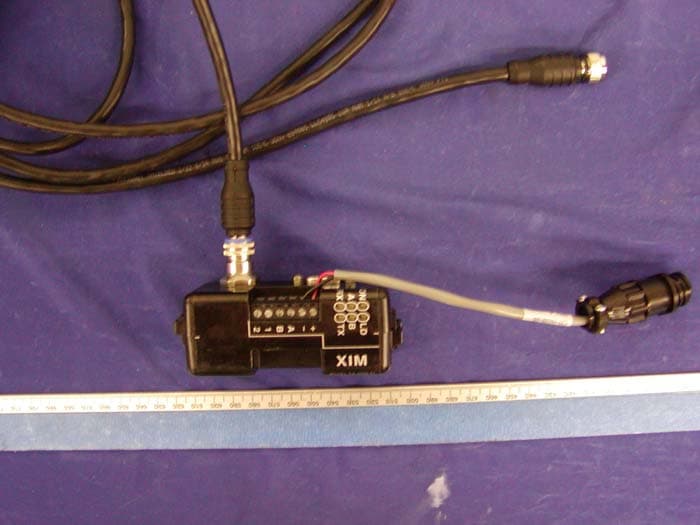
Click to zoom
Application Details
- Equipment Class
- PCB - PCS Licensed Transmitter
- Date of Grant
- Oct 11, 2004
- Application Purpose
- Original Equipment
- Date of Application
- Oct 11, 2004
- Equipment Note
- Onboard information system
- Frequency Range
- 1851.25000000 - 1908.75000000
- Company
- Xata Corporation
- Country
- United States
Documents & Files
Document Text
Text extracted from the exhibit documents filed with the FCC. Open a document above to read the original.
Users Manual
Onboard Fleet Management System Overview 151 East Cliff Road – Suite 10 – Minneapolis, MN 55337 – 1.800.745.9282 – www.xata.com Optimizing Fleet Efficiency System Overview XATA Onboard Computer System Page 2 XATA ONBOARD is a state-of-the-art onboard information system that integrates onboard computing, real-time communications, global positioning, and advanced fleet management software into an enterprise-wide logistics solution for America’s largest fleets. XATA ONBOARD combines 15 years of experience and expertise in delivering onboard application software with state-of-the-art technology and platforms that provide a path to the future. Transportation professionals confirm again and again the pivotal role of onboard technology in helping fleets improve their productivity and profitability. In order to achieve measurable increases, fleet managers must integrate onboard technology into the fleet management process. The XATA System does just that. Its combination of ease-of-use and greater functionality has lead to overwhelming acceptance by such nationally known fleets as AmeriServe, BOC Gases, Coca-Cola, EOTT, Safeway, Supervalu, Ruan, Ryder, Penske, Unisource, and Whirlpool. XATA’s onboard computer is an essential productivity tool for the professional driver that helps him contribute to the overall success of the company. The onboard computer and powerful fleet management software unifies drivers and fleet managers into a single team with the power to drive out cost and drive up service. System Components The XATA System consists of six basic components: • Driver Computer • Data Station • Driver Key • XATA Application Module • OpCenter • SmartCom Each component of the XATA System has a basic function that it performs as part of its role in the total system. Driver Computer The Driver Computer has a large, touch-sensitive, easy to read, user-friendly screen which provides instant feedback to the driver. It requires little training and interacts with the driver by simply touching the screen. The Driver Computer has a very high level of acceptance among drivers because it makes the job so much easier. For starters, you have a paperless interactive trip plan, paperless state fuel tax data capture, and a DOT certified paperless driver's log. It is a professional system for the professional driver, not a vehicle recording system that is used by a driver. Besides the easy onboard operation, the XATA system gives the driver important information about each day's routes. The system tells the driver where to go, when to be there, and what to do. The trip plan is always available for the driver's review. All data that is captured by the Driver Computer is presented to the driver first. The driver can read and interact with the system at all times. It's as if each driver has their own onboard advisor . System Overview XATA Onboard Computer System Page 3 Driver Key Each driver has an electronic key which stores the driver's identity, the driver's log, dispatch data, and trip data. It has the capacity to hold multiple trips. Besides serving as a data storage device, the Driver Key transports information to and from the Driver Computer and Data Stations for collection purposes, utilizing the key receptacles built into both devices. Because each key contains a computer memory chip, the Driver Key provides a portable, powerful, efficient and secure method for transporting information in a paperless, electronic format. Data Station Data Stations contain the same hardware as the Driver Computer, but utilize different software. The Data Stations are located where trips begin and end. The data station gives the driver his dispatch data on a Driver Key at the beginning of trips and offloads actual trip data from the driver's key at the end of trips. The Data Station connects directly to a PC or to a modem, giving you the capability to transfer information to or from your PC or from any remote site. Drivers can access the Data Station at any time, allowing them to operate on their schedule without the need to physically interchange paper with management. XATA Application Module The XATA Application Module (XAM) is the most technologically advanced onboard computer available on the market today. The XAM and our Driver Computer form an advanced client/server architecture that extends the life of our customer’s existing onboard computer system and enables the deployment of new applications in the future using this powerful platform. Using this client/server architecture, the XAM contains and executes multiple onboard applications in a multi-tasking real time environment while providing extensive connectivity to vehicle networks, peripheral devices, and other server devices. The XAM serves as the primary application platform for our onboard computer system by: • Providing processor and memory resources for more advanced applications. • Supporting connectivity to multiple peripheral devices. • Providing the architecture to support the use of GPS and real-time communications. • Increasing the level of systems integration in the vehicle. • Creating an architecture that is modular, scaleable, expandable, and open. . The XAM is a small, rugged dome that mounts outside the vehicle. Inside is a state-of-the art onboard computer, GPS and optional wireless communications. System Overview XATA Onboard Computer System Page 4 OpCenter In an open, multi-user, Windows environment, OpCenter collects, validates and processes data recorded by a fleet’s network of XATA onboard computers – then stores the information in an open SQL database for further analysis and reporting. It also automatically delivers this information in a user-friendly, intelligent format over an interactive desktop interface. OpCenter provides a decision support environment for the entire distribution team that reduces operating costs, improves safety, streamlines compliance reporting, and automates data collection for other systems. By integrating all fle…
Text truncated - open the document above for the full version.
Users Manual
FLEET INTELLIGENCE The Web-based fleet management system with an affordable entry point to quickly improve operations across any-sized fleet . System Overview Know What Matters. 2 ` XATANET Overview XATANET Benefits: o Eliminates the need for a substantial capital investment o Offers a lower cost of entry and ownership o Expands as your business grows or changes o Requires minimal training for drivers and fleet operators o Automates labor-intensive, error-prone processes o Reduces the time required for deployment o Configures to best meet your needs o Anywhere, anytime access via a Web browser o No software or hardware purchase or installation o Minimal IT support o Costs are structured and predictable XATANET is a flexible, expandable, online fleet management solution that is easy to use and delivers a rapid return on investment. Your Fleet, Your Future, Your Flexibility. XATA has recast 20 years of experience designing, developing and delivering fleet management solutions into a new Web-based platform – XATANET. XATANET is delivered as a hosted service, allowing a fleet to deploy an enterprise-wide fleet management solution rapidly and cost-effectively, without placing time intensive and expensive demands on its IT infrastructure, staff or budget. Enterprise Architecture. Centralized Infrastructure. XATANET is 100% web-based, and delivered through an ASP model, allowing your fleet to rapidly and cost- effectively utilize fleet management technology, while avoiding the pain and expense of installing, maintaining and upgrading packaged software. XATANET provides the applications, hosting and services via a centralized infrastructure – delivering full-featured fleet management functionality and unlimited scalability at a monthly cost based on how you configure your system. Software That Sets The Standard. XATANET delivers a powerful software platform of integrated fleet management applications designed to solve problems core to operating, managing and maintaining a fleet of trucks. This new system provides you with the right information at the right time in the right place – from hours of service status to delivery notification to fuel economy performance – helping you make the decisions that lead to improved fleet productivity and profitability, quickly and effectively. XATANET is the only fleet management software that automatically collects, transforms and delivers exactly what you need to know about your fleet in order to drive operational results and business performance by delivering this fleet intelligence right to your desktop. XATANET Hosting: XATANET is hosted in a Tier One data center owned and managed by Agiliti, a leading provider of hosting, network management and professional services that delivers complete availability, reliability and security to more than 400 customers. 3 ` XATANET: THE ASP ALTERNATIVE XATANET is delivered as a completely managed, outsourced service that XATA hosts, maintains and upgrades for a predictable, ongoing monthly fee based on usage. The ASP alternative With ASPs, businesses can forego the need to make expensive upfront hardware investments and instead, pay for only those applications they need and cost-effectively scale up or down their application usage as demand requires. Depending on the application and the business requirement, this approach delivers numerous benefits: • Lower upfront costs. Since the ASP operates and maintains the application and has invested in the back-end hardware needed to run it, businesses don’t have to buy expensive new hardware and pricey software licenses. Depending on the application, this can save tens or hundreds of thousands of dollars in upfront costs. • Lower ongoing costs. ASPs eliminate the need for internal IT personnel to support and maintain an application. The only technology involved may be a web browser and dial-up or broadband IT connection. (For fleet management applications, onboard truck units will be required). This changes IT to a monthly expense – scaled to actual usage – instead of a large capital investment. • Faster application deployment. In addition to lower costs, a hosted and managed application can be deployed in much less time than an internal application. “Deployment” for the business user may be simply a matter of setting up and activating an account. Upgrades to the host software are implemented automatically, as well, since they are delivered over the Internet. • Reliability and security. Established ASPs maintain “Tier One” data centers – technologically sophisticated facilities built that provide more application reliability and data security than businesses can typically afford on their own. Moreover, Tier One centers are staffed by personnel whose sole job is protecting, maintaining and backing up data. Due to the sophistication of their IT infrastructures, ASPs commonly maintain 99+ percent uptime. • Anytime-anywhere access. Customers can access their applications and data 24/7 from any Web browser. And since the application interface is a browser, deployment to The ASP model: An application service provider (ASP) is a company that offers businesses access to applications and related services over the Internet that would otherwise have to be located on their own computers. This is called managed hosting. Instead of buying software licenses, customers pay a monthly usage fee. Overall costs are usually less, sometimes substantially less, than outright application ownership and maintenance. However, with an ASP, a business is able to derive most if not all the benefits of owning and operating the application itself. Sometimes called “renting” or “leasing” applications, the ASP model has become an important alternative to owning and operating applications. Small companies with limited budgets benefit by access to applications that otherwise would be unaffordable, and can better focus on their core business competencies, not on maintaining large and expensive IT units. The ASP app…
Text truncated - open the document above for the full version.
Cover Letter(s)
Federal Communications Commission Authorization and Evaluation Division Confidentiality Request regarding application for certification of FCC ID; POCQ2438F Pursuant to Sections 0.457 and 0.459 of the Commission’s Rules, we hereby request confidential treatment of information accompanying this application as outlined below: 1. Parts List EA-0066-02 3_1.doc 2. Schematics SE-0066 3 Sheet1.pdf, SE-0066 3 Sheet2.pdf 3. Block Diagrams The above materials contain trade secrets and proprietary information not customarily released to the public. The public disclosure of these materials may be harmful to the applicant and provide unjustified benefits to its competitors. The applicant understands that pursuant to Section 0.457 of the Rules, disclosure of this application and all accompanying documentation will not be made before the date of the Grant for this application. Sincerely, Dennis A. Quy VP Hardware Engineering XATA Corporation 151 E. Cliff Road, Suite 10 Burnsville, MN 55337 phone: 612-894-3680 fax: 612-894-2463 http://www.xata.com
External Photos
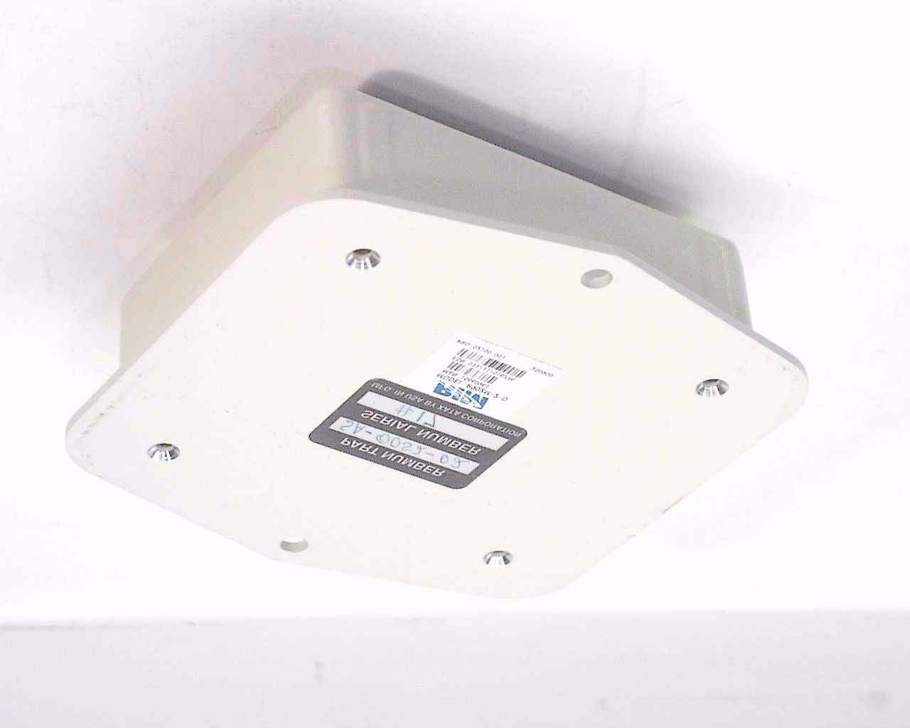
EXHIBIT C - EUT EXTRNAL PHOTOGRAPHS EUT – Front View EUT – Back View EUT – Port View XIM Interface Module and Cable EUT – Antenna View
Internal Photos
EXHIBIT C - EUT INTRNAL PHOTOGRAPHS EUT – Component View EUT – Component View without Shielding EUT – Solder View
Operational Description
Wavecom Wismo Quik Q2438 Module RF Circuitry Description: Frequency Tuning This product has factory preset frequency adjustment. There is no frequency field adjustment for this product. In the field, frequency is locked to the base station and controlled by the VCTCXO adjustments to offset any possible error. Limiting Power Each mobile is individually calibrated at the factory to ensure a minimum MAX power of 23.0dBm (Cellular and PCS CDMA) and MIN power of –50dBm by employing proper frequency and temperature compensation schemes for both the RX and TX automatic gain control (AGC) amplifier. Suppression of Spurious Radiations Spurious and harmonic suppression is achieved by proper design with various filters and sufficient use of metallic shields. Rigorous testing at the factory ensures continuous compliance. Frequency Stability A voltage controlled temperature compensated crystal oscillator (VCTCXO) is utilized as a frequency reference for all of the transceiver local oscillators. This crystal oscillator is specified to a frequency stability of +/- 2.5ppm. The synthesizer lock status is constantly monitored by the microprocessor and transmission is disabled whenever an out of lock condition is detected. The mobile is locked to the base station and makes necessary frequency adjustments on the VCTCXO to correct and frequency errors between the mobile and the base station. Limiting Modulation The audio input is sampled, digitally limited, and then filtered to an amplitude and frequency limit the signal applied to the modulator. The device supports IS-2000 for CDMA operation, and IS-98 for AMPS operation. The device has an operating temperature of –30 o C to +60 o C. The functions include a compandor, PLL lock detector, filtering of received data, audio signal filtering for signals.
Parts List/Tune Up Info
Wavecom Wismo Quik Q2438 Module RF Circuitry Description: Frequency Tuning This product has factory preset frequency adjustment. There is no frequency field adjustment for this product. In the field, frequency is locked to the base station and controlled by the VCTCXO adjustments to offset any possible error. Limiting Power Each mobile is individually calibrated at the factory to ensure a minimum MAX power of 23.0dBm (Cellular and PCS CDMA) and MIN power of –50dBm by employing proper frequency and temperature compensation schemes for both the RX and TX automatic gain control (AGC) amplifier. Suppression of Spurious Radiations Spurious and harmonic suppression is achieved by proper design with various filters and sufficient use of metallic shields. Rigorous testing at the factory ensures continuous compliance. Frequency Stability A voltage controlled temperature compensated crystal oscillator (VCTCXO) is utilized as a frequency reference for all of the transceiver local oscillators. This crystal oscillator is specified to a frequency stability of +/- 2.5ppm. The synthesizer lock status is constantly monitored by the microprocessor and transmission is disabled whenever an out of lock condition is detected. The mobile is locked to the base station and makes necessary frequency adjustments on the VCTCXO to correct and frequency errors between the mobile and the base station. Limiting Modulation The audio input is sampled, digitally limited, and then filtered to an amplitude and frequency limit the signal applied to the modulator. The device supports IS-2000 for CDMA operation, and IS-98 for AMPS operation. The device has an operating temperature of –30 o C to +60 o C. The functions include a compandor, PLL lock detector, filtering of received data, audio signal filtering for signals.
Test Report
Note: The test report is specially limited to the above company and the product model only. It may not be duplicated without prior written consent of Bay Area Compliance Laboratory Corporation. This report must not be used by the client to claim product certification, approval, or endorsement by NVLAP, NIST or any agency of the US Government. FCC PART 24 TYPE APPROVAL EMI MEASUREMENT AND TEST REPORT For XATA Corporation 151 East Cliff Rd Burnsville, MN 55337 FCC ID: POCQ2438F This Report Concerns: Original Report Equipment Type: Onboard Information System Test Engineer: Ming Jing / Report No.: R0409142 Report Date: 2004-10-01 Reviewed By: Hang Tan / Prepared By: Bay Area Compliance Laboratory Corporation (BACL) 230 Commercial Street Sunnyvale, CA 94085 Tel: (408) 732-9162 Fax: (408) 732 9164 XATA Corporation FCC ID: POCQ2438F Report # R0409142Rpt.doc Page 2 of 24 FCC Part 24 Type Approval Report TABLE OF CONTENTS GENERAL INFORMATION.......................................................................................................................................4 PRODUCT DESCRIPTION FOR EQUIPMENT UNDER TEST (EUT) ....................................................................................4 OBJECTIVE...................................................................................................................................................................4 RELATED SUBMITTAL(S)/GRANT(S).............................................................................................................................4 TEST METHODOLOGY..................................................................................................................................................4 TEST FACILITY.............................................................................................................................................................4 SYSTEM TEST CONFIGURATION ..........................................................................................................................6 JUSTIFICATION.............................................................................................................................................................6 BLOCK DIAGRAM.........................................................................................................................................................6 EQUIPMENT MODIFICATIONS.......................................................................................................................................6 LOCAL SUPPORT EQUIPMENT LIST AND DETAILS........................................................................................................6 REMOTE SUPPORT EQUIPMENT LIST AND DETAILS......................................................................................................6 EXTERNAL CABLES LIST AND DETAILS........................................................................................................................6 CONFIGURATION OF TEST SYSTEM..............................................................................................................................7 TEST SETUP BLOCK DIAGRAM.....................................................................................................................................7 SUMMARY OF TEST RESULTS ...............................................................................................................................8 §2.1047 - MODULATION CHARACTERISTIC .......................................................................................................9 APPLICABLE STANDARD..............................................................................................................................................9 TEST PROCEDURE........................................................................................................................................................9 TEST EQUIPMENT LIST AND DETAILS...........................................................................................................................9 ENVIRONMENTAL CONDITIONS....................................................................................................................................9 TEST RESULTS.............................................................................................................................................................9 §2.1053 - SPURIOUS RADIATED EMISSIONS .....................................................................................................10 APPLICABLE STANDARD............................................................................................................................................10 TEST PROCEDURE......................................................................................................................................................10 TEST EQUIPMENT LIST AND DETAILS.........................................................................................................................10 ENVIRONMENTAL CONDITIONS..................................................................................................................................10 TEST RESULT.............................................................................................................................................................11 §2.1046, & §24.232 - RF POWER OUTPUT.............................................................................................................12 APPLICABLE STANDARD............................................................................................................................................12 TEST PROCEDURE......................................................................................................................................................12 TEST EQUIPMENT LIST AND DETAILS.........................................................................................................................13 ENVIRONM…
Text truncated - open the document above for the full version.
Test Report
RF EXPOSURE According to §15.247(b)(4) and §1.1307(b)(1), systems operating under the provisions of this section shall be operated in a manner that ensures that the public is not exposed to radio frequency energy level in excess of the Commission’s guidelines. According to §1.1310 and §2.1093 RF exposure is calculated. Limits for Maximum Permissive Exposure (MPE) Frequency Range (MHz) Electric Field Strength (V/m) Magnetic Field Strength (A/m) Power Density (mW/cm 2 ) Averaging Time (minute) Limits for General Population/Uncontrolled Exposure 0.3-1.34 614 1.63 *(100) 30 1.34-30 824/f 2.19/f *(180/f 2 ) 30 30-300 27.5 0.073 0.2 30 300-1500 / / f/1500 30 1500-15000 / / 1.0 30 f = frequency in MHz * = Plane-wave equivalent power density MPE Prediction Predication of MPE limit at a given distance Equation from page 18 of OET Bulletin 65, Edition 97-01 S = PG/4πR² Where: S = power density P = power input to antenna G = power gain of the antenna in the direction of interest relative to an isotropic radiator R = distance to the center of radiation of the antenna Maximum peak output power at antenna input terminal: 30.17 (dBm ) Maximum peak output power at antenna input terminal: 1039.92 (mW) Prediction distance: 20 (cm) Predication frequency: 1880 (MHz) 13dBi Panel Antenna, Antenna Gain (typical): 2.2 (dBi) antenna gain: 1.66 (numeric) Power density at predication frequency at 20 cm: 0.34 (mW/cm 2 ) MPE limit for uncontrolled exposure at prediction frequency: 1.0 (mW/cm 2 ) Test Result The EUT is defined as a mobile device since the predicted power density level at 20 cm is 0.34 mW/cm². This is below the uncontrolled exposure limit of 1.0mW/cm² at 1880 MHz.
Contact Information
Applicant
Dennis Quy(VP Hardware Engineering)
Test Firm
Bay Area Compliance LaboratoryJohn Chan
Technical Specifications
| # | Rule Parts | Frequency Range | Power Output | Emission | Tolerance |
|---|---|---|---|---|---|
| 1 | 24E | 1.85 GHz - 1.91 GHz | 1.04 W | 1M27G1D | 2.5000000000 ppm |
Other Applications from Xata Corporation
POC-R902
Aug 20, 2001OEM Radio Modem
Equipment Class
TNB - Licensed Non-Broadcast Station Transmitter