POPFMTRANSMITTERFM Transmitter
Ucentric Systems LLC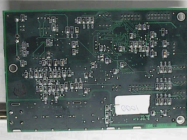
Click to zoom
Application Details
- Equipment Class
- DXX - Part 15 Low Power Communication Device Transmitter
- Date of Grant
- Jul 21, 2001
- Application Purpose
- Original Equipment
- Date of Application
- Jul 21, 2001
- Equipment Note
- FM Transmitter
- Frequency Range
- 91.10000000 - 95.90000000
- Company
- Ucentric Systems LLC
- Country
- United States
Documents & Files
Document Text
Text extracted from the exhibit documents filed with the FCC. Open a document above to read the original.
Users Manual
Installation Guide Ucentric Systems Home Area Network Server DRAFT COPY FOR INTERNAL REVIEW PURPOSES ONLY Updated Revision: Alpha 2.0B1 PROPRIETARY INFORMATION December 13, 2000 Ucentric Systems LLC 2 Clock Tower Place, Suite 550 Maynard, Massachusetts 01754 Tel: 978-823-8100 © Copyright 2000 Ucentric Systems, LLC All Rights Reserved. Reproduction, adaptation, or translation without prior written permission from Ucentric Systems is prohibited, except as allowed under copyright laws. Printed in USA Wa rra n ty Information in this document ap- plies to the Alpha-2 version of the Home Server and is subject to change without notice. Ucentric Systems, LLC makes no warranty of any kind with regard to this document and in- formation, included, but not lim- ited to, the implied warranties or merchantability and fitness for a particular purpose. Ucentric Systems, LLC shall not be liable for errors contained herein or for incidental or conse- quential damages in connection with the furnishing, perfor- mance, or use of this document. FCC Statement This equipment has been tested and found to comply with the limits for a Class B digital device, pursuant to Part 15 of the FCC rules. These limits are designed to provide reasonable protection against harmful interference in a residential installation. This equipment generates, uses and can radiate radio frequency energy and, if not installed and used in accordance with the instructions, may cause harmful interference to radio communications. However, there is no guarantee that interference will not occur in a particular installation. If this equipment does cause harmful interference to radio or television reception, which can be determined by turning the equipment off and on, the user is encouraged to try to correct the interference by one or more of the following measures: - Reorient or relocate the receiving antenna. - Increase the separation between tween the equipment and the receiver. - Connect the equipment into an outlet on a circuit different from that to which the receiver is connected. - Consult the dealer or an experienced radio/TV technician for help. Changes and modifications not expressly approved by the manufacturer or registrant of this equipment can void your authority to operate this equipment under Federal Communications Commission rules. FCC Part 68 Compliance 1. This equipment complies with Part 68 of the FCC rules. This unit bears a label which contains the FCC registration number ringer equivalence number (REN). If requested, this infor- mation must be provided to the telephone company. 2. This equipment used the fol- lowing standard jack types for network connection: RJ11. 3. This equipment contains an FCC compliant modular jack. It is designed to be connected to the telephone network or premises wiring using compatible modular plugs and cabling which comply with the requirements of FCC Part 68 rules. 4. The Ringer Equivalence Num- ber, or REN, is used to determine the number of devices which may be connected to the tele- phone line. An excessive REN may cause the equipment to not ring in response to an incoming call. In most areas, the sum of the RENs of all equipment on a line should not exceed five (5.0). 5. In the unlikely event that this equipment causes harm to the telephone network, the telephone company can temporarily dis- connect your service. The tele- phone company will try to warn you in advance of any such dis- connection, but if advance notice isn’t practical, it may disconnect the service first and notify you as soon as possible afterwards. In the event such a disconnection is deemed necessary, you will be advised of your right to file a complaint with the FCC. 6. From time to time, the tele- phone company may make changes in its facilities, equip- ment, or operations which could affect the operation of this equip- ment. If this occurs, the tele- phone company is required to provide you with advance notice so you can make the modifica- tions necessary to maintain unin- terrupted service. 7.Forrepairorwarrantyservice contact: Mack Technologies Inc. 27 Carlisle Road, Westford, MA 01886 8. This device contains no user serviceable parts. INDUSTRY CANADA ES-003 Compliance NOTICE: The industry Canada label identifies certified equip- ment. This certification means that the equipment meets tele- communications network protec- tive, operation and safety requirements as prescribed in the appropriate Terminal Equipment Technical Requirements docu- ment(s). The Department does not guarantee the equipment will operate to the user’s satisfaction. Before installing this equipment, users should ensure that it is per- missible to be connected to the facilities of the local telecommu- nications company. The equip- ment must also be installed using an acceptable method of connec- tion. The customer should be aware that compliance with the above conditions may not pre- vent degradation of service in some situations. Repairs to certified equipment should not be coordinated by a representative designated by the supplier. Any repairs or alter- ations made by the user to this equipment, or equipment mal- functions, may give the telecom- munications company cause to request the user to disconnect the equipment. Users should ensure for their own protection that the electrical ground connections of the power utility, telephone lines and internal metallic water pipe sys- tem, if present, are connected to- gether. This pre-caution may be particularly important in rural ar- eas. CAUTION: Users should not at- tempt to make such connections themselves, but should contact the appropriate electric inspec- tion authority, or electrician, as appropriate. NOTICE: The Ringer Equiva- lence Number (REN) assigned to each terminal device provides an indication of the maximum num- berofterminalsallowedtobe connected to a telephone inter- face. The termination on an inter- face may consist of any combination of devices subject only to the requirement that …
Text truncated - open the document above for the full version.
Cover Letter(s)
Curtis-Straus LLC 527 Great Road Littleton, Massachusetts 01460 Tel: 978.486.8880 Fax: 978.486.8828 Web: www.curtis-straus.com e-mail: [email protected] Worldwide Regulatory Approvals Experts ® June 26, 2001 Federal Communications Commission 7435 Oakland Mills Road Columbia, MD 21046 Gentlemen: This letter is to comply with Section 0.457(d)(2)(I) pertaining to confidential material. Ucentric Systems requests that the following documents regarding this submission for FCC ID: POPFMTRANSMITTER be kept confidential: 1. Block diagram 2. Schematic 3. Circuit Description 4. Bill of Materials The material above contains trade secrets or technical data which would customarily be guarded from competitors. We respectfully request that these documents not be available to the general public. Sincerely, Michael Buchholz EMC Manager
Cover Letter(s)
Please see responses and attachments below: If you have any other questions, please let me know. -Mike 1. Please provide data responsive to the power supply voltage variation requirements or 15.31(e). The product uses an off the shelf PC power supply. These supplies have historically proven to be very stable and do not vary with minor changes in input AC voltage. 2. The photos are identified as the FCC ID: UCSFMTRANSMITTER. Please explain. At the time the photos were taken, Ucentric indicated that thier grantee code was UCS. It was determined at a later date that this is incorrect. Corrected in new photo attachment. 3. I appear to have only one side of the transmitter base board. Please provide a set of photos which includes both sides of the base board. See new photo attachment. 4. Where is the base transmitter located in the setup photo? The base transmitter is located unter the ground plane. The base transmitter setup is in every way identical to that which was tested at Integrity. We believed it would be much easier to characterize the modified splitter without having to manually weed out the known emissions from the base unit. 5. The label does not contain the required 15.19(a)(3) statement. The device is small enough to qualify under 15.19(a)(5), but in that case the statement must appear in the manual. Please provide either a revised label or a revised manual. The label containing the required warnings is located on the base unit. The FCC ID label is on the splitter unit. Base unit label is attached. 6. The document "technicaljustification" which includes the Integrity test report is too large to submit to the FCC. Please provide an unprotected pdf copy of this document and I will extract the pages to submit to the FCC. I plan on sending only the third ITDS test report to the FCC. This should get it below the 2MB limit allowed by the FCC. Requested report is attached. Best regards Barry C. Quinlan Certification & Telecom Manager ----------------------------------------------------- -------------------------- Curtis-Straus LLC Voice: 978.486.8880 x270 527 Great Road Fax: 978.486.8828 Littleton, MA 01460 http://www.curtis-straus.com --------------------------------------------------------------------------------
External Photos
Equipment Photos Ucentric Home Server (system) FCC ID: POPFMTRANSMITTER Ucentric Home Server (base unit transmitter board - top) FCC ID: POPFMTRANSMITTER Ucentric Home Server (base unit transmitter board - bottom) FCC ID: POPFMTRANSMITTER Ucentric Home Server (splitter) FCC ID: POPFMTRANSMITTER Ucentric Home Server (splitter – top with cans) FCC ID: POPFMTRANSMITTER Ucentric Home Server (splitter - bottom) FCC ID: POPFMTRANSMITTER Ucentric Home Server (splitter – top without cans) FCC ID: POPFMTRANSMITTER
Internal Photos
Equipment Photos Ucentric Home Server (system) FCC ID: POPFMTRANSMITTER Ucentric Home Server (base unit transmitter board - top) FCC ID: POPFMTRANSMITTER Ucentric Home Server (base unit transmitter board - bottom) FCC ID: POPFMTRANSMITTER Ucentric Home Server (splitter) FCC ID: POPFMTRANSMITTER Ucentric Home Server (splitter – top with cans) FCC ID: POPFMTRANSMITTER Ucentric Home Server (splitter - bottom) FCC ID: POPFMTRANSMITTER Ucentric Home Server (splitter – top without cans) FCC ID: POPFMTRANSMITTER
Test Report
Report # 66595.e1 37-7 Ayer Road Littleton, MA 01460 Page Tel: (978) 486-0432 Fax: (978) 486-0592 Email: [email protected] 1 of 29 Test Report Standard(s): FCC Part 15 Class B Model(s): Ubox Home Internet Server Model 1A001-01 Prepared for: Ucentric Systems 2 Clock Tower Place / Suite 550 Maynard, MA 01754 Date(s) of test: February 8, 2001 Prepared by: _________________________________Date______________ Dan Alvarez, Compliance Engineer Reviewed by: _________________________________Date_____________ Michael Koffink, EMI Section Manager Report # 66595.e1 37-7 Ayer Road Littleton, MA 01460 Page Tel: (978) 486-0432 Fax: (978) 486-0592 Email: [email protected] 2 of 29 Insert certificate Report # 66595.e1 37-7 Ayer Road Littleton, MA 01460 Page Tel: (978) 486-0432 Fax: (978) 486-0592 Email: [email protected] 3 of 29 This report may not be reproduced in parts without the written consent of Integrity Design & Test Services, Inc. This report must not be used to claim product endorsement by NVLAP or any agency of the United States government. Report # 66595.e1 37-7 Ayer Road Littleton, MA 01460 Page Tel: (978) 486-0432 Fax: (978) 486-0592 Email: [email protected] 4 of 29 Table of Contents 1. EXECUTIVE SUMMARY.........................................................................................6 1.1 SCOPE...................................................................................................................6 1.2 CONTENT..............................................................................................................6 1.3 CONCLUSIONS.......................................................................................................6 2. TEST ENVIRONMENT............................................................................................7 2.1 EUT DESCRIPTION................................................................................................7 2.2 TEST FACILITY DESCRIPTION................................................................................10 2.3 TEST EQUIPMENT................................................................................................10 2.4 PRODUCT DISPOSITION........................................................................................10 3. TEST DESCRIPTION/RESULTS............................................................................13 3.1 RADIATED EMISSIONS..........................................................................................13 3.2 CONDUCTED EMISSIONS......................................................................................16 3.3 LABELING REQUIREMENTS.................................................................................20 APPENDIX A – TEST DATA.........................................................................................23 CONFIGURATION PHOTOGRAPHS..........................................................................26 Report # 66595.e1 37-7 Ayer Road Littleton, MA 01460 Page Tel: (978) 486-0432 Fax: (978) 486-0592 Email: [email protected] 5 of 29 List of Tables TABLE 2.3-1: TEST EQUIPMENT...................................................................................11 TABLE 3.1.1-1: FCC CLASS B RADIATED EMISSIONS LIMIT..............................................19 TABLE 3.2.1-1: FCC CLASS B CONDUCTED EMISSIONS LIMIT..........................................19 TABLE A1: FCC CLASS B RADIATED EMISSIONS....................................................24 TABLE A2: FCC CLASS B CONDUCTED EMISSIONS................................................25 Report # 66595.e1 37-7 Ayer Road Littleton, MA 01460 Page Tel: (978) 486-0432 Fax: (978) 486-0592 Email: [email protected] 6 of 29 1. Executive Summary 1.1 Scope This document describes electromagnetic emissions testing performed on the Ubox Home Internet Server Model 1A001-01 on February 8, 2001, pursuant to FCC CFR 47 Part 15. It may be used to demonstrate compliance with the FCC emissions requirements under a Declaration of Conformity (DoC) as well as Canadian emissions requirements regulated by Industry Canada as defined in ICES-003 Issue 2, Revision 1. 1.2 Content Contained herein are the technical descriptions of the equipment under test (EUT) as well as the test methods and results used to verify compliance with the emissions requirements for Information Technology Equipment (ITE), to the above named standards. 1.3 Conclusions The Ubox Home Internet Server Model 1A001-01 met the FCC Class B requirements when tested as described herein. (Refer to Test Descriptions & Results in section 3 for a detailed description). Report # 66595.e1 37-7 Ayer Road Littleton, MA 01460 Page Tel: (978) 486-0432 Fax: (978) 486-0592 Email: [email protected] 7 of 29 2. Test Environment 2.1 EUT Description M/N: Ubox Home Internet Server Model 1A001-01 S/N: FCC Test Sample #10 (Revised) Description: The Ubox Home Internet Server is a control center for connecting high-speed Internet access with other home appliances, PCs, entertainment devices, and phone services. The unit will typically be installed where other home services (cable, electric, telephone) enter the residence and will use pre-existing wiring in the home. FCC Test sample #10 - Ubox consisting of: Test Config: 1A0010-01 Description Manufacturer Part Number Serial Number Motherboard w/ Intel Celeron 600 MHz SuperMicro 370SWT SS102379 Hard Disk Drive 1 Quantum Fireball Lct15-7.5Gb SG0285TC1254207M32VP Hard Disk Drive 2 Seagate ST310211A 7DB00T3K TV Tuner/Digitizer Happauge WinTV-GO Model 190 1975093 Ethernet - 10/100Base T (2) Linksys LNE100Tx C9B-00866816 C9B-00863231 Video Modulator Peracom PC Caster Rev D Proto #11 Power Supply Fortron Source FSP250-60GNA 4882A248 Ucentric ADSL Card Ucentric Systems LLC 1000070-01 4 Ucentric FM Transmitter Ucentric Systems 1000080-01 Mike #2-Revised per ECO Ucentric Telephony Board Ucentric Systems LLC AX03 None Ucentric IR Modulator Ucentric Systems LLC 1000120-01 1 Ucentric IR Eye Ucentric Systems LLC 1000360-01 2 Uce…
Text truncated - open the document above for the full version.
Test Report
MEASUREMENT/TECHNICAL REPORT Company - Model: Ucentric Systems Ucentric Home Server FCC ID: POPFMTRANSMITTER June 26, 2001 Description: This is a report to support a request for an original grant of equipment authorization. Equipment Type: Low Power Communications Device Transmitter (DXX) Report prepared for:Ucentric Systems 2 Clock Tower Place Maynard, MA 01754 Phone:(978) 897-6482 Fax:(978) 897-9980 Report prepared by:Evan D. Gould Curtis-Straus LLC 527 Great Road Littleton, MA 01460 USA Phone:978-486-8880 FAX:978-486-8828 FCC Application for Ucentric Systems •• FCC ID: POPFMTRANSMITTER •• Report No. EB0510-1 9-Jul-01 ______________________________________________________________________ _____________________________________________________________ Curtis-Straus LLC •• 527 Great Road •• Littleton, MA •• TEL (978) 486-8880 •• FAX (978) 486-8828 page 2 of 17 Introduction This report is an application for Certification of a Transmitter operating pursuant to Part 15.239 of the FCC Rules, Code of Federal Regulations 47. This report is designed to demonstrate the compliance of this device with the requirements outlined in Part 15 of CFR 47 using the methods outlined in Part 2 of CFR 47. The confidential information and descriptions included in this application are detailed descriptions of the products, block diagrams, component specifications, and schematic diagrams. We hereby respectfully request under the provision of section 0.457d of the code that the documents listed below be held confidential. Technical Descriptions and Block Diagrams Schematics Bill of Materials Ucentric Systems is requesting that the Technical Descriptions, Block Diagrams, Schematics and Bill of Materials be kept confidential in the FCC application because of the proprietary design developed by Ucentric Systems that is unique to the industry. FCC Application for Ucentric Systems •• FCC ID: POPFMTRANSMITTER •• Report No. EB0510-1 9-Jul-01 ______________________________________________________________________ _____________________________________________________________ Curtis-Straus LLC •• 527 Great Road •• Littleton, MA •• TEL (978) 486-8880 •• FAX (978) 486-8828 page 3 of 17 Summary The Ucentric Home Server System consists of a Base Unit (Model #’s: 1A0000-01, 1A0010-01, 1A0020-01, 1A0030-01, 1A0040-01, 1A0050-01, 1A0060-01, and 1A0070-01) and a Splitter (U.S. Model # UC60-00120-01, Canada Model # UC60-00121-01) which transmits to a TV and FM receiver via cables. Alternatively, the Splitter can utilize an antenna to transmit to the FM receiver. Testing was performed using the 1A0030-01 Base Unit. The different Base Unit model numbers indicate the LAN/WAN selection that is installed at the factory, which affects the choices between Ethernet, ADSL, or HPNA cards utilized for each network connection. These different network connection configurations have no bearing on the outcome of this testing. The unintentional emissions from the system utilizing the cables were measured by Integrity Design & Test Services, Inc. (NVLAP Lab Code: 200004-0, Report # 66397.e2). The measurements conducted at Curtis-Straus were to determine what additional emissions exist due to the added antenna, as generated in the base unit and splitter. The data from Curtis-Straus and Integrity was then analyzed to determine compliance as a Part 15 transmitter. Statement of Conformity The Ucentric Home Server has been found to conform with the following parts of the 47 CFR as detailed below: Part 2Part 15Comments 15.15(b)The product contains no user accessible controls that increase transmission power above allowable levels. 2.925 15.19The label is shown in the label exhibit. 15.21Information to the user is shown in the instruction manual exhibit. 15.27No special accessories are required for compliance. 15.203The antenna connector is not accessible to the user and therefore cannot be easily removed. (the antenna connector is inside the chassis underneath a soldered metal can) 15.205 15.209 The fundamental is not in a Restricted band and the spurious and harmonic emissions in the Restricted bands comply with the general emission limits of 15.209. 15.207The unit complies with the line conducted emission requirements of 15.207. 15.239(a)The unit complies with the bandwidth requirement of 15.239(a) with maximum input signal. The unit is tuned with software and therefore cannot operate outside the range of 88-108MHz pursuant to the requirement in 15.239(a) 15.239(b)&(c)The unit complies with the field strength limits referred to in 15.239(b) & (c). FCC Application for Ucentric Systems •• FCC ID: POPFMTRANSMITTER •• Report No. EB0510-1 9-Jul-01 ______________________________________________________________________ _____________________________________________________________ Curtis-Straus LLC •• 527 Great Road •• Littleton, MA •• TEL (978) 486-8880 •• FAX (978) 486-8828 page 4 of 17 Test Methodology Radiated emission testing was performed according to the procedures in ANSI C63.4 (1992). Radiated testing was performed at an antenna to EUT distance of 1 or 3 meters. The actual test distance used is noted in the test data sheets. The device’s performance was investigated to 2GHz. Since the antenna can be operated in any orientation, the emissions were maximized in each of the three orthogonal axes and the maximum reading was recorded. The unit can be operated only at 200kHz increments from 91.1MHz to 95.9MHz. Three different operating frequencies were selected according to ambient conditions at the time. Harmonics of the fundamental were measured only for the unit operating at 91.7MHz due to the fact that emissions at those harmonic frequencies were below the noise floor. FCC Application for Ucentric Systems •• FCC ID: POPFMTRANSMITTER •• Report No. EB0510-1 9-Jul-01 ______________________________________________________________________ _____________________________________________________________ Curtis-Straus LLC •• 527 Great Road •• Littleton, MA •• TEL (…
Text truncated - open the document above for the full version.
Test Setup Photos
Page 1 of 1 file://E:\Ucentric\B0510\B0510 RE front.jpg5/23/01
Contact Information
Applicant
Mike Morrow(Senior Compliance Engineer)
Test Firm
Curtis-Straus LLCJonathan Stewart
Technical Specifications
| # | Rule Parts | Frequency Range | Power Output |
|---|---|---|---|
| 1 | 15C | 91.1 MHz - 95.9 MHz | - |