PP9P2000MOBITEXPoint of Sale Terminal
Descartes Corp.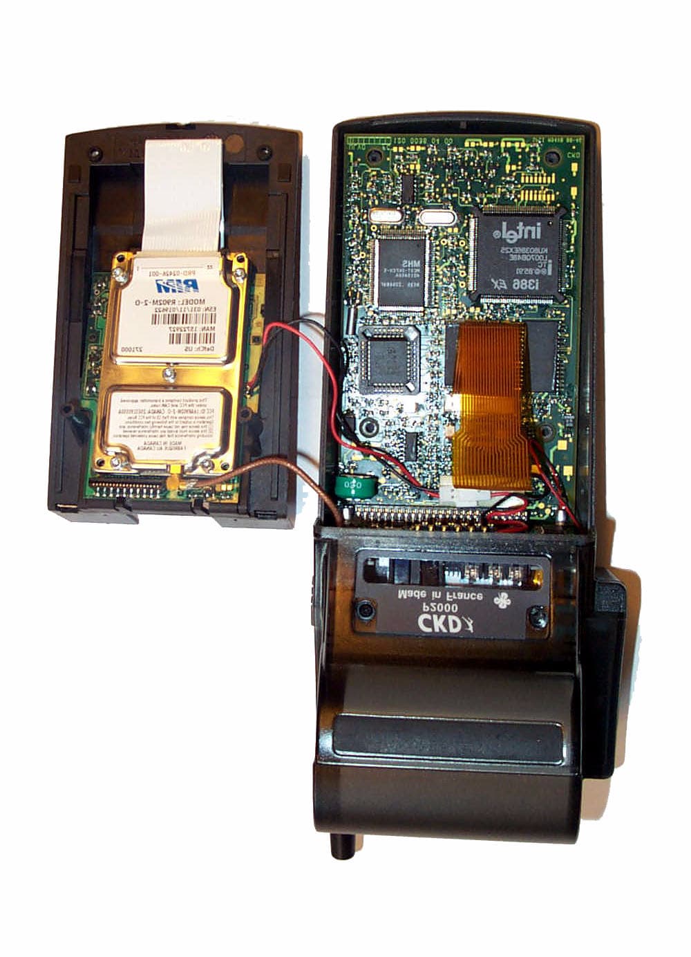
Click to zoom
Application Details
- Equipment Class
- TNB - Licensed Non-Broadcast Station Transmitter
- Date of Grant
- Oct 28, 2001
- Application Purpose
- Original Equipment
- Date of Application
- Aug 19, 2001
- Equipment Note
- Point of Sale Terminal
- Frequency Range
- 896.00000000 - 902.00000000
- Company
- Descartes Corp.
- Country
- United States
Documents & Files
Document Text
Text extracted from the exhibit documents filed with the FCC. Open a document above to read the original.
Attestation Statements
July 2001 APREL Project No.: Consulting * Research * Training * Certification Testing Since 1981 FCC ID: PP9P2000MOBITEX Exhibit 10 Attestation Statements FCC Part 15, Subpart B Class B Certificate of Conformity FCC Part 2 & 90 Statement of Compliance July 2001 APREL Project No.: Consulting * Research * Training * Certification Testing Since 1981 Certificate of Compliance FCC ID: PP9P2000MOBITEX PRODUCT: Point of Sale Terminal MODEL: P2000 MANUFACTURER: Descartes Corp. We certify that the pertinent tests have been performed on the above-described equipment and that this equipment conforms to the applicable requirements of FCC Parts 2, 15 and 90. See Exhibit 2, Engineering Reports Jayanta (Jay) K. Sarkar Technical Director, Standards and Certification APREL Laboratories
Cover Letter(s)
July 2001 APREL Project No.: Consulting * Research * Training * Certification Testing Since 1981 FCC ID: PP9P2000MOBITEX Table of Contents List of Exhibits Submitted E E X X H H I I B B I I T T 1 1 : : C C O O V V E E R R L L E E T T T T E E R R S S a) Application overview b) Equipment Identification c) Authorization Letter /Agent Designated (Jay Sarkar) d) Request for confidentiality e)Authorization letter from Research In Motion allowing use of FCC approved radio modem (FCC ID: L6AR902M-2-0) in the Descartes Point of Sale Terminal, P2000 Exhibit 2:Engineering Reports (Test Reports) a) ERP (2.1046) b) Radiated Spurious Emissions (2.1053) c) Bandwidth (2.1049) Modulation Characteristics (2.1047) d) Spurious Emissions at Antenna Terminal (2.1051) e) Frequency Stability (2.1055) Exhibit 3: Operational/Technical Description Exhibit 4: ID Label/Location Exhibit 5:External Photographs of the Equipment Internal Photographs of the equipment Exhibit 6:Block Diagram (Confidential) Exhibit 7: Schematic Diagram (Confidential) Exhibit 8:Parts List (Confidential), Tune–up Procedure Exhibit 9:User’s Manual Exhibit 10:a) Attestation Statement: FCC Part 15 Declaration of Conformance (DoC) certificate b) Attestation Statement: the equipment complies with Part 90 Exhibit 11:RF Exposure Information: SAR Report (Includes Test Set-up Photographs)
Cover Letter(s)
July 2001 APREL Project No.: Consulting * Research * Training * Certification Testing Since 1981 FCC ID: PP9P2000MOBITEX Exhibit 1 a) Application overview b) Equipment c) Authorization Letter /Agent Designated (Jay Sarkar) d) Request for confidentiality e)Authorization letter from Research In Motion allowing use of FCC approved radio modem (FCC ID: L6AR902M-2-0) in the Descartes Point of Sale Terminal, P2000 July 2001 APREL Project No.: Consulting * Research * Training * Certification Testing Since 1981 EXHIBIT 1b Equipment Identification FCC ID: PP9P2000MOBITEX MANUFACTURER: Descartes Corp. PRODUCT: Point of Sale Terminal MODEL: P2000 EUT TYPE: Licensed Non-Broadcast Station Transmitter (TNB) TX Frequency: 896-902 MHz MEASURED ERP: 0.363 W Colonial lake Drive, Lawrenceville, NJ 08648 Tel: (800) 510-0120 Tel: (609) 530-9440 Fax: (609)530-9445 Email: [email protected] www.descartesusa.com Date: 08/08/2001 Federal Communications Commission Equipment Authorization Branch 7435 Oakland Mills Road Columbia MD 21406 In regards to: Descartes Corp. FCC ID:PP9P2000Mobitex Description of Product as it is to be Marketed: Model: P2000 Mobitex Request for Confidentiality Gentlemen: In accordance with 0.459 of CFR 47, Descartes Corp., Inc. hereby requests confidentiality of the Block Diagram, Schematic Diagrams and Parts List for the attached test report. These documents contain detailed system and equipment description and related information About the product which Descartes Corp. considers to be proprietary, confidential, and a custom design and, otherwise, would not release to the general public. Since this design is a basis from which future technological products will evolve, Descartes Corp. considers this information would be of benefit to its competitors, and that the disclosure of the information in these documents would give competitors an unfair advantage in the market. Sincerely David C. Lesage Executive Vice President RESEARCH IN MOTION Research In Motion Limited 295 Phillip Street Waterloo, Ontario Canada N2L 3W8 +1 519 888 7465, fax +1 519 888 6906 E-mail: [email protected] July 26, 2001 Federal Communications Commission Equipment Authorization Division Application Processing Branch 7435 Oakland Mills Rd. Columbia, Md. 21046 To whom it may concern, Descarte, of Lawrenceville, New Jersey, is our customer in good standing and will be producing a Point of Sale (POS) product which incorporates the RIM 902M radio modem module (FCC ID L6AR902M-2-O). Descarte will be submitting an application for certification of the final integrated product with a unique FCC ID using their own grantee code. Descarte will submit SAR and ERP data for the final integrated product. For information about the radio modem module please refer to RIM’s submission FCC ID L6AR902M-2-O. In the past, this method has allowed our customers to integrate the radio modem module without repeating FCC part 90 testing or accessing RIM proprietary confidential information. RIM does not disclose proprietary confidential information about our products. Our FCC submissions are considered proprietary confidential information. Should you have any questions, please do not hesitate to contact our Senior Certification Engineer, Masud Attayi, at (519) 888-7465 x2442 or by email at [email protected]. Yours truly, Andy Clipsham OEM Product Manager Research In Motion Limited +1-519-888-7465 x2482 [email protected]
External Photos
July 2001 APREL Project No.: Consulting * Research * Training * Certification Testing Since 1981 FCC ID: PP9P2000MOBITEX Exhibit 5 Photographs of the Equipment External Photos Internal Photos
ID Label/Location Info
July 2001 APREL Project No.: Consulting * Research * Training * Certification Testing Since 1981 FCC ID: PP9P2000MOBITEX Exhibit 4 FCC ID Label/Location
Operational Description
July 2001 APREL Project No.: Consulting * Research * Training * Certification Testing Since 1981 FCC ID: PP9P2000MOBITEX Exhibit 3 Operational/Technical Description P2000 MOBITEX Technical / Functional description The P2000 MOBITEX payment terminal is a self contained unit, comprising a Processor Board, a magnetic card swipe reader, a smart card reader , a printer, and a MOBITEX radio at 896 to 902 Mhz , via a 1/8 λ Helical antenna. Fig.1 P2000 MOBITEX The Unit operates at 4 levels: 1 The operating System, 2 The Kernel. 3 The payment application. 4 The communication protocol While the P2000 is on the base, the battery is in the charge mode and the unit is powered up. And is capable of communicating with payment processors via a choice of radio, or modem, depending on the original set up. While off the base, the P2000 MOBITEX can only communicate with the processors via the MOBITEX radio. During periods of inactivity (beyond thirty seconds), the P2000 enters a sleep mode, during which all systems are down. The Terminal operation consists of the following typical steps: A transaction is selected by pressing a selected key: A credit card is swiped through the reader, which captures the pertinent Credit card Data. A purchase (or credit) amount is entered via the Keypad Certain other information such as Employee number, password, etc is keyed in as well when prompted by the display The transaction data is formatted according to the Credit card processor’s message format, and protocol and passed on to the MOBITEX Radio, which transmits the authorization request to the card processor via TCPIP. The processor returns the authorization (or denial) Back to the MOBITEX radio, which communicates it back to the terminal. All prompts, activity and results are displayed on the display screen. The built in thermal printer then prints a receipt. The detail of all these operations are described in the document entitled “P2000 User’s Manual” Technical Specifications: Intel® 32 bits micro-processor. Applications stored in memory FLASH. Transactions stored in battery secured memory. Partitioned memory. 1 Mbytes of memory in basic version. High speed, high resolution graphic thermal printer allowing printouts of personalized logos and bitmaps in less than 3 seconds. Card Readers : - Magstripe : ISO 1/2. - Smart Card: ISO 7816 (EMV, synchronous / asynchronous). 17 keys: 10 numeric and 7 functions. NI-MH battery pack allows more than 200 transactions. Infrared EFT to base communication. Battery charging and modem base. Alphanumeric screen displays 2 lines of 16 characters. Audio warning and paper feedback. Modem multi-norms V21, V22, V22bis, V23, Bell 103, Bell 212 A.. Radio Specifications pertinent to the operation of the P2000 terminal: Type: Research in Motion Rim R902M MOBITEX Modem Power: 2.0 Watts Max Transmit Frequency: 896 to 902 Mhz Receive Frequency: 935 to 941 Mhz Fig.2 Rim R902M MOBITEX Modem
RF Exposure Info
July 2001 APREL Project No.: Consulting * Research * Training * Certification Testing Since 1981 FCC ID: PP9P2000MOBITEX Exhibit 11 RF Exposure Information SAR Report Certification Report on Specific Absorption Rate (SAR) Experimental Analysis Descartes Corp. Point of Sale Terminal P2000 Test Date: July 2001 51 Spectrum Way Nepean ON K2R 1E6 Tel: (613) 820-2730 Fax: (613) 820-4161 email: [email protected] This report shall not be reproduced, except in full, without the express written permission of APREL Laboratories DESB-P2000 W. 902M Mobitex-3682 A143-P2000 Page 2 of 17 Project #: DESB-P2000 w. 902M Mobitex-3682 51 Spectrum WayTel. (613) 820-2730 Nepean, Ontario, K2R 1E6 Fax (613) 820 4161 e-mail: [email protected]© APREL 2000 This report shall not be reproduced, except in full, without the express written approval of APREL Laboratories. FCC ID:PP9P2000MOBITEX Applicant:Descartes Corp. Equipment:Point of Sale Device with a RIM 902M Mobitex Modem Model:P2000 Standard:FCC 96 –326, Guidelines for Evaluating the Environmental Effects of Radio- Frequency Radiation ENGINEERING SUMMARY This report contains the results of the engineering evaluation performed on a P2000 POS Terminal which incorporates a RIM 902M Mobitex modem. The measurements were carried out in accordance with FCC 96-326. The P2000 POS Terminal was evaluated for its maximum power level 0.363W (ERP). The radio modem was tested at a duty cycle of 25%. The duty cycle can not be changed by the end user. The P2000 POS Terminal was tested at low, middle, and high channels for the keyboard up, keyboard down, left, and right sides. The maximum 10g SAR (1.23 W/kg) was found to coincide with the peak performance RF output power of channel 0720 (899MHz) for the left side of the device with the antenna 4.5 mm away from the phantom. (The hot spot is located on the antenna). Test data and graphs are presented in this report. At a separation distance of 4 cm from the antenna of the device, the maximum 1g SAR is 0.02 W/kg. The manual will have a warning to keep bystanders, and parts of the user’s body other than extremities, at least 4 cm away from the antenna. Based on the test results and on how the device will be marketed and used, it is certified that the product meets the requirements as set forth in the above specifications, for RF exposure environment. (The results presented in this report relate only to the sample tested.) Page 3 of 17 Project #: DESB-P2000 w. 902M Mobitex-3682 51 Spectrum WayTel. (613) 820-2730 Nepean, Ontario, K2R 1E6 Fax (613) 820 4161 e-mail: [email protected]© APREL 2000 This report shall not be reproduced, except in full, without the express written approval of APREL Laboratories. TABLE OF CONTENTS 1.Introduction.........................................................................................................................4 2.Applicable Documents.......................................................................................................4 3.Device Under Investigation................................................................................................4 4.Test Equipment...................................................................................................................5 5.Test Methodology...............................................................................................................5 6.Test Results.........................................................................................................................6 6.1.Transmitter Characteristics.................................................................................................6 6.2.SAR Measurements............................................................................................................7 7.User’s Hand Exposure........................................................................................................8 8.Bystander Exposure............................................................................................................9 9.Conclusions.......................................................................................................................11 APPENDIX A. Measurement Setup, Tissue Properties and SAR Graphs...............................12 APPENDIX B. Uncertainty Budget............................................................................................14 APPENDIX C. Validation Scan on a Flat Phantom...................................................................15 APPENDIX D. Probe Calibration...............................................................................................17 TABLES AND FIGURES Table 1. Sampled RF Power.........................................................................................................6 Table 2. SAR Measurements........................................................................................................8 Table 3. SAR versus DUI-Phantom Separation........................................................................10 Figure 1. Setup Figure 2. Setup Closeup..............................................................................12 Table 4. Dielectric Properties of the Simulated Muscle Tissue at 899 MHz...........................12 Figure 3. Contour Plot of the Area Scan 2.5mm Above Phantom Surface...............................13 Figure 4. Surface Plot of the Area Scan 2.5mm Above Phantom Surface................................13 Table 5. Uncertainty Budget.......................................................................................................14 Figure 5. Contour Plot of the Reference Area Scan 2.5mm Above Phantom..........................15 Figure 6. Surface Plot of the Reference Area Scan 2.5mm Above Phantom...........................15 Figure 7. Peak Local SAR versus Separation (1 gram SAR).....................................................16 Page 4 of 17 Project #: DESB-P2000 w. 902M Mobitex-3682 51 Spectrum WayTel. (613) 820-2730 Nepean, Ontario, K2R…
Text truncated - open the document above for the full version.
Test Report
July 2001 APREL Project No.: Consulting * Research * Training * Certification Testing Since 1981 FCC ID: PP9P2000MOBITEX Exhibit 2a Engineering Report on ERP (2.1046) Assessment of Compliance for Measurement of Effective Radiated Power (ERP) in Accordance with the FCC Rules & Regulations Part 2.1046 and 90 Point of Sale Terminal P2000 with a Research In Motion R902-M-2-0 radio transmitter Descartes Corp. 51 Spectrum Way Nepean ON K2R 1E6 Tel: (613) 820-2730 Fax: (613) 820-4161 email: [email protected] July 2001 DESB-P2000 w. 902Dmobitex-3681 This report shall not be reproduced, except in full, without the express written approval of APREL Laboratories July 2001 Page 2 APREL Project No DESB-P2000 w. 902Dmobitex-3681 This report shall not be reproduced, except in full, without the express written approval of APREL Laboratories Consulting * Research * Training * Certification Testing Since 1981 FCC ID:PP9P2000MOBITEX Applicant:Descartes Corp. Equipment:Point of Sale Terminal Model:P2000 Standard:FCC Rules and Regulations Part 2.1046 and 90 ENGINEERING SUMMARY This report contains the results of the effective radiated power (ERP) measurement performed on a Descartes Corp. Wireless Point of Sale Terminal operating with a built-in Research in Motion MOBITEX radio transmitter. The measurements were carried out in accordance with the FCC Rules and Regulations Part 2.1046 and 90. The product was evaluated for ERP when it was set at the maximum power level. Descartes Corp. P2000 was tested for ERP at high, middle, and low frequencies with the maximum ERP obtained at channel No.: 720 with the frequency being 901.00 MHz. The test data is presented in this report under the section: Test Results. The measured ERP is 0.363 W. (The results presented in this report relate only to the sample tested.) July 2001 Page 3 APREL Project No DESB-P2000 w. 902Dmobitex-3681 This report shall not be reproduced, except in full, without the express written approval of APREL Laboratories Consulting * Research * Training * Certification Testing Since 1981 Summary of the Results Test DescriptionPage No. Test Set-up Figure No. Results Summary RF Power Output as Radiated Ref. Paragraph 2.1046 and 9081 Passed July 2001 Page 4 APREL Project No DESB-P2000 w. 902Dmobitex-3681 This report shall not be reproduced, except in full, without the express written approval of APREL Laboratories Consulting * Research * Training * Certification Testing Since 1981 INTRODUCTION General This report describes the results of the effective radiated power (ERP) measurement conducted on a Descartes Point of Sale Terminal model: P2000 operating with a built-in Research in Motion MOBITEX radio transmitter. Test Facility The tests were performed for Descartes by APREL Laboratories at APREL’s EMI facility located in Nepean, Ontario, Canada. The laboratory operates an (3m and 10m) Open Area Test Site (OATS). The measurement facility is calibrated in accordance with ANSI C63.4-1992. A description of the measurement facility in accordance with the radiated and AC line conducted test site criteria per ANSI C63.4-1992 is on file with the Federal Communications Commission and is in compliance with the requirements of Section 2.948 of the Commissions rules and regulations. APREL’s registration number is: 90416 APREL is accredited by Standard Council of Canada. APREL is also accredited by Industry Canada and recognised by the Federal Communications Commissions (FCC). Standard The evaluation and analysis were conducted in accordance with FCC Rules and Regulations Parts 2.1046 and the appropriate limits. Test Equipment The test equipment used during the evaluation is listed in Appendix A with calibration due dates. Environmental Conditions Measurements were conducted in open area test site. - Temperature:25 °C ± 2 - Relative Humidity:30 - 50 % - Air Pressure:101 kPa ± 3 July 2001 Page 5 APREL Project No DESB-P2000 w. 902Dmobitex-3681 This report shall not be reproduced, except in full, without the express written approval of APREL Laboratories Consulting * Research * Training * Certification Testing Since 1981 FCC SUBMISSION INFORMATION FCC ID:PP9P2000MOBITEX Equipment:Point of Sale Terminal Model:P2000 For:Certification Applicant:Descartes Corp.. Colonial Lake Drive Lawrenceville, NJ 08648 U.S.A. Manufacturer: Descartes Corp.. Colonial Lake Drive Lawrenceville, NJ 08648 U.S.A. Evaluated by:APREL Laboratories 51 Spectrum Way Nepean, Ontario Canada K2R 1E6 July 2001 Page 6 APREL Project No DESB-P2000 w. 902Dmobitex-3681 This report shall not be reproduced, except in full, without the express written approval of APREL Laboratories Consulting * Research * Training * Certification Testing Since 1981 Test:RF Power Output as Radiated (ERP) Ref.:FCC Part 2 paragraph 2.1046 and 90 Criteria:N/A Set-up:See Figure No. 1. Equipment:See Appendix A. Methodology:RF Power Measurement by Radiated Method (ERP): Test site: The radiated RF power measurement was taken at APREL Laboratory’s open area test site (OATS). This open area test site is calibrated to ANSI C63.4 document and a description of the measurement facility is on file with the Federal Communications Commission and is in compliance with the requirement of Section 2.948 of the Commissions rules and regulations. (FCC File No.: 90416) The test was set-up as illustrated in Fig.1. The DUI was configured to operate at maximum power with carrier unmodulated. The equipment under test was placed on a turntable positioned 3 m away from the calibrated receiving antenna, which in turn was connected to the spectrum analyzer. For each transmitter frequency, the received signal was maximised by rotating the turntable and adjusting the height of the receiving antenna. To obtain the actual ERP, the DUI was replaced by a vertically polarised half-wave dipole antenna resonant to that frequency and fed by a RF power amplifier and signal generator. The center of the dipole antenna was placed precisely in the same location as th…
Text truncated - open the document above for the full version.
Test Report
July 2001 APREL Project No.: Consulting * Research * Training * Certification Testing Since 1981 FCC ID: PP9P2000MOBITEX Exhibit 2c Engineering Report on Bandwidth (2.1049) Modulation Characteristics (2.1047) RESEARCH IN MOTION Document R902M-2-O RADIO MODEM DEVICE OCCUPIED BANDWIDTH/BANDWIDTH LIMITATIONS Page 1(4) Author Data Masud S. Attayi Date April 8, 1999 Document No. 01947-CERT-FCC-TEST-BW_MASK ApprovedRevFile / Reference BW_MASK Copyright 1999, Research In Motion, Limited OCCUPIED BANDWIDTH/BANDWIDTH LIMITATIONS TEST PROCEDURE: The Research In Motion Limited R902M-2-O radio modem device was connected together with a radio monitor board 02120-001, host computer, external power supply, a 20 dB external attenuator, and a coaxial cable. The R902M-2-O antenna output terminal was connected to the input of a 50 : spectrum analyzer through a matched 20 dB attenuator and a coaxial cable. The R902M-2-O transmitter was operating at full and low output power with and without internal data modulation. TEST RESULTS: UNMODULATED CARRIER, High Power: 11.97 dBm with a 20 dB external attenuator and a 1 m coaxial cable. a)Internal Modulation: Please refer to the attached spectrum analyzer plots. 100% of the in-band modulation is below the specified mask per 90.210(j) UNMODULATED CARRIER, Low Power: -2.53 dBm with a 20 dB external attenuator and 1 m coaxial cable. b)Internal Modulation: Please refer to the attached spectrum analyzer plots. 100% of the in-band modulation is below the specified mask per 90.210(j) Below is the description of the mask for band 896-901/935-940 MHz (Mobitex) : 2 Watts transmitter Frequency (MHz) FormulaUpper Limit (dB) Lower Limit (dB) -2650050+10 log (P)-53-175 -0.0115 157 log (f d e 5.3) -53-175 -0.0095 157 log (f d e 5.3) or 103 log(f d e 3.9) -39.8-175 -0.0062 103 log (f d e 3.9) or 53 log (f d e 2.5) -21.1-175 -0.0025 53 log (f d e 2.5) 0.0-175 0.0025 53 log (f d e 2.5) 0.0-175 0.0062 103 log (f d e 3.9) or 53 log (f d e 2.5) -21.1-175 Document R902M-2-O RADIO MODEM DEVICE OCCUPIED BANDWIDTH/BANDWIDTH LIMITATIONS Page 2(4) Date April 8, 1999 RevDocument No. 01947-CERT-FCC-TEST-BW_MASK Copyright 1999, Research In Motion, Limited RESEARCH IN MOTION 0.0095 157 log (f d e 5.3) or 103 log (f d e 3.9) -39.8-175 0.0115 157 log (f d e 5.3) -53-175 2650050+10 log (P)-53-175 EQUIPMENT: x H.P. 8563E Spectrum Analyzer 9.0 KHz - 26.5 GHz x HP6632A DC POWER SUPPLY x Mini Circuits 20 dB att. # NAT-20 0 Hz - 1.5 GHz SETTING: RBW: 300 Hz; VBW: 3 MHz; SPAN: 25 KHz; SWP: 10 Sec OCCUPIED BANDWIDTH/BANDWIDTH LIMITATIONS UNMODULATED CARRIER – HIGH POWER Document R902M-2-O RADIO MODEM DEVICE OCCUPIED BANDWIDTH/BANDWIDTH LIMITATIONS Page 3(4) Date April 8, 1999 RevDocument No. 01947-CERT-FCC-TEST-BW_MASK Copyright 1999, Research In Motion, Limited RESEARCH IN MOTION OCCUPIED BANDWIDTH/BANDWIDTH LIMITATIONS UNMODULATED CARRIER – LOW POWER OCCUPIED BANDWIDTH/BANDWIDTH LIMITATIONS MODULATED CARRIER – HIGH POWER Document R902M-2-O RADIO MODEM DEVICE OCCUPIED BANDWIDTH/BANDWIDTH LIMITATIONS Page 4(4) Date April 8, 1999 RevDocument No. 01947-CERT-FCC-TEST-BW_MASK Copyright 1999, Research In Motion, Limited RESEARCH IN MOTION OCCUPIED BANDWIDTH/BANDWIDTH LIMITATIONS MODULATED CARRIER – LOW POWER
Test Report
July 2001 APREL Project No.: Consulting * Research * Training * Certification Testing Since 1981 FCC ID: PP9P2000MOBITEX Exhibit 2d Engineering Report on Spurious Emissions at Antenna Terminal (2.1051) RESEARCH IN MOTION Document R902M-2-O RADIO MODEM DEVICE SPURIOUS EMISSIONS AT ANTENNA TERMINALS Page 1(1) Author Data Masud S. Attayi Date April 8, 1999 Document No. 01947-CERT-FCC-TEST-SPURIOUS ApprovedRevFile / Reference Spurious Copyright 1999, Research In Motion, Limited SPURIOUS EMISSIONS AT ANTENNA TERMINALS TEST PROCEDURE: The Research In Motion Limited R902M-2-O radio modem device was connected together with a radio monitor board 02120-001, host computer, external power supply, a 20 dB external attenuator, and a coaxial cable. The R902M-2-O antenna output terminal was connected to the input of a 50 : spectrum analyzer through a matched 20 dB attenuator and a coaxial cable. The transmitter was operating at full output power with and without internal data modulation. The calculated limit below the unmodulated carrier at +12.1 dBm, including the 20 dB external attenuator and 1 dB cable loss, is +33.1 dBm. The actual limit is 53.1 dBc lower, or -20.0 dB. TEST RESULTS: Ref 899+33.1 (- 53.1) -20.0 FREQUENCY MHz LEVEL dBm LIMIT dB 89933.1 1,798-37.0-20.0 2,697-39.3-20.0 3,596-62.9-20.0 4,495-55.1-20.0 5,394-39.8-20.0 6,293-41.7-20.0 7,192-73.1-20.0 8,091-57.2-20.0 8,990-66.5-20.0 NOTE: The above limits take into account the unmodulated carrier level of 33.1 dBm inclusive of the 20 dB external attenuator and 1 dB coaxial cable loss. The modulation used was a worst case, random data pattern while still representing a normal modulation pattern. EQUIPMENT: x H.P. 8563E Spectrum Analyzer 9.0 KHz - 26.5 GHz x HP6632A DC POWER SUPPLY x Mini Circuits 20 dB att. # NAT-20 0 Hz - 1.5 GHz
Test Report
July 2001 APREL Project No.: Consulting * Research * Training * Certification Testing Since 1981 FCC ID: PP9P2000MOBITEX Exhibit 2e Engineering Report on Frequency Stability (2.1055) RESEARCH IN MOTION Document R902M-2-O RADIO MODEM DEVICE FREQUENCY STABILITY PROCEDURES Page 1(4) Author Data Masud S. Attayi Date April 8, 1999 Document No. 01947-CERT-FCC-TEST-013 ApprovedRevFile / Reference 013 Copyright 1999, Research In Motion, Limited CFR 47 Chapter 1 - Federal Communication Commission Rules Part 2 Required Measurement 2.995Frequency Stability - Procedures (a,b)Frequency Stability - Temperature Variation (d)Frequency Stability - Voltage Variation Part 90 Subpart I : Technical Standards 90.213Frequency Tolerance (a)Maintain the carrier frequency within 0.00015 % (1.5 ppm) of the assigned frequency. (b) Maximum power output used for measurement Frequency and power measurements were performed together with the same set up. Frequency and power data were both recorded across temperature and voltage. The set up used a cable assembly with a power splitter to allow concurrent measurements with the frequency counter, the power meter and the signal generator. The cable assembly was calibrated to allow compensation of the insertion loss between the transmitter and the power meter. Calibration for the Cable and Attenuator Loss: Place: RF Lab in RIM. Date: March 14, 1999 Time: 08:26:00. Instruments used: InstrumentSerial NumberCalibrated on Network Analyzer HP 8753D 3410A0590508/08/98 Calibration Kit HP85033D 3423A0073420/08/98 Procedure: Full Two port Calibration of 8753D using the 85033D was done. An assembly of Cables, Attenuator, power splitter, and connectors was made for making RF power measurements. Attenuator: 20dB, DC to 1500 MHz - Mini-Circuits model no: NAT-20 Power splitter: 4.93 dB - Mini-Circuits model no: 15542 ZN3PD 900W The total loss of this cable assembly from the RF input to the RF output was measured to be 26.83 dB at 899.0 +/- 3 MHz. Document R902M-2-O RADIO MODEM DEVICE FREQUENCY STABILITY PROCEDURES Page 2(4) Date April 8, 1999 RevDocument No. 01947-CERT-FCC-TEST-013 Copyright 1999, Research In Motion, Limited RESEARCH IN MOTION Power and frequency measurements of RIM Radio at different temperatures: Place: RF Lab in RIM Date: March 23 1999 Instruments used: InstrumentSerial numberCalibrated on DC Power supply HP 6632A3524A1401205/08/98 Universal Counter HP 53131A 3325A0098804/08/98 Power Meter HP EPM-441AGB3748130029/04/98 Power Sensor HP ECP-E18AUS3718126005/05/98 Signal Generator HP 8648A3636A0279925/11/98 RIM 2181 DSP board Temperature Chamber used: Manufacturer: Envirotronics Model: SH8C Serial No: 01984093-S-10860 Procedure: The RIM Radio modem device R902M-2-O was placed in the Temperature chamber and connected to the instruments outside as shown in the figure below. Dry air was pumped inside the temperature chamber to maintain a back pressure during the test. The Radio was kept in the off condition at all times except when the measurements were to be made. 10m Coax cable 2 m Coax cable RX/TX Antenna Connector 1 m Coax Cable 5 m Coax Cable Rim Radio R902M-2-O Power Sensor ECP-E18A Counter HP53131A Mini Circuits 15542 ZN3PD-900W 09746 20dB Attenuator Signal Generator 8648A RIM DSP Data Generator OEM Document R902M-2-O RADIO MODEM DEVICE FREQUENCY STABILITY PROCEDURES Page 3(4) Date April 8, 1999 RevDocument No. 01947-CERT-FCC-TEST-013 Copyright 1999, Research In Motion, Limited RESEARCH IN MOTION The chamber was switched on and the temperature was set to -30 q C. After the chamber stabilized at -30 q C there was a soak period of one hour to alleviate moisture in the chamber. The Radio was switched on and frequency and power measurements were made as follows: The RIM Radio automated test utility was controlled by computer. This application was given ward of activating all machines intrinsic to the temperature test. It controls the HP 53131A universal counter, HP 6623A power supply, HP EPM-441A power meter and HP 8648A signal generator by GPIB Bus. The Environmental Chamber was instructed through a RS-232 serial line. The RIM…
Text truncated - open the document above for the full version.
Contact Information
Applicant
David M Lesage(Executive Vice President)
Technical Contact
APREL LaboratoriesJayanta (Jay) K Sarkar
[email protected](613)820-2730
51 Spectrum Way · Nepean, Ontario · Canada
Non-Technical Contact
APREL LaboratoriesJayanta (Jay) K Sarkar
[email protected](613)820-2730
Test Firm
APREL LaboratoriesJay Sarkar
Technical Specifications
| # | Rule Parts | Frequency Range | Power Output | Emission | Tolerance |
|---|---|---|---|---|---|
| 1 | 90 | 896 MHz - 902 MHz | 363.00 mW | 12K8F1D | 1.5000000000 ppm |
Other Applications from Descartes Corp.
PP9P2000CDPD
Nov 01, 2001Portable Credit Card Terminal
Equipment Class
TNB - Licensed Non-Broadcast Station Transmitter