PPCTX01AWireless Garage Door Opener
F2P Electronics, Inc.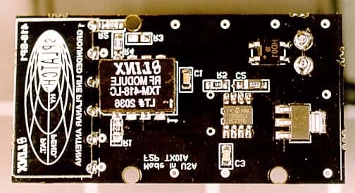
Click to zoom
Application Details
- Equipment Class
- DSC - Part 15 Security/Remote Control Transmitter
- Date of Grant
- Jul 10, 2002
- Application Purpose
- Original Equipment
- Date of Application
- Jul 10, 2002
- Equipment Note
- Wireless Garage Door Opener
- Frequency Range
- 418.00000000 - 418.00000000
- Company
- F2P Electronics, Inc.
- Country
- United States
Documents & Files
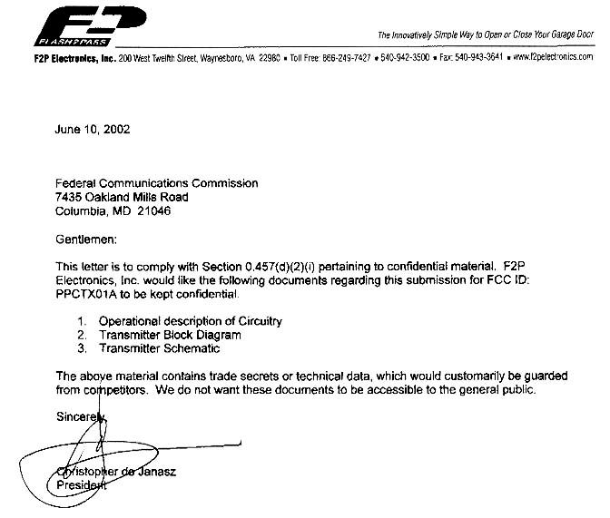
Document Text
Text extracted from the exhibit documents filed with the FCC. Open a document above to read the original.
Users Manual
Installation Instructions Tools needed Phillips screwdriver Test light or voltmeter Drill with #35 (.110 or 7/64”) bit Pliers Electrical tape Vehicle compatibility The Flash2Pass transmitter is designed to work with most current model automobiles and light duty trucks as well as motorcycles*, snowmobiles or any vehicle with a 6 or 12-volt electrical system. Vehicles with the "flash to pass" feature allow the Flash2Pass transmitter to be operated anytime because power is continuously sent to the headlight high beam switch. If your vehicle does not have the "flash to pass" feature, your headlights will have to be on to send power to the bright switch for Flash2Pass to operate. *Harley-Davidson Motor Company is the exclusive licensee for motorcycles. Please see your local Harley-Davidson dealer for motorcycle compatibility. Garage door/gate opener compatibility The Flash2Pass receiver is compatible with most garage door/gate openers made since April 1982. Wiring your Flash2Pass Receiver (Garage) Remove the wall button from the wall and disconnect the two wires attached to the button. Carefully remove the backing plate of the Flash2Pass receiver and pull the wires through the large square cutout. Attach the Flash2Pass receiver's backing plate to the wall with the two screws supplied being careful not to pinch the wires or put a screw through them, and run them through the notch at the top of the plate. If the two low-voltage wires from the garage door opener come through a standard single-gang electrical junction box, align the screw holes of the backing plate to those of the box, and attach with your existing screws. Some garage door opener buttons might have a multi-function switch incorporated into the unit. If you wish to keep these other functions (i.e. separate light switch, lock), attach “jumper” wires (not included) from the Flash2Pass receiver to the multi-function units positive terminal for the garage door opener, and to the units ground terminal. If you do not use the other functions, or you want to discontinue the use of the other functions, remove the old unit, determine which wire is the common ground, and which of the other three controls the garage door opener. Attach these two wires (ground and garag e do o r po sitive ) to the Flash2Pass receiver as described below and separately wrap the other two wires with electrical tape, and twist them out of the way. Connect the two wires from the garage door opener (one each) to the screws at the back of the Flash2Pass receiver. No need to worry about positive or negative polarity, the device determines this automatically. Snap the receiver to the backing plate on the wall. Plug the garage door opener back in or turn on the power. The LED on the face of the Flash2Pass receiver should flash steadily, indicating the system is operating properly. If the LED does not flash, this could indicate that there is no power in the wires coming from the garage door opener motor. Make sure you plugged the garage door opener back in or turned the power back on. If the power is back on, and your old button was not lit, you will need to purchase a Flash2Pass AC adapter, Part No. 101301 from your Flash2Pass dealer or order it directly from the factory. It simply plugs into the bottom of the receiver and a standard wall outlet. Wiring your Flash2Pass Transmitter (Vehicle) The Flash2Pass transmitter operates on your vehicles 12-volt electrical system. Under the hood of your vehicle, locate a suitable mounting location for the Flash2Pass transmitter where it will not be exposed to direct splashing water. Flash2Pass should be mounted as close to the front of the engine compartment to maximize transmission range of the radio signal. It must be located in close proximity (18") of the headlight wires. An ideal location in many vehicles is on the top or side of a wheel well. Prior to mounting Flash2Pass, complete the wiring connections. First, you need to locate the headlight high beam wire. The high beam lead will be attached to the back of the headlight via a plug with two or three wires coming from it. Unplug the headlight and attach the test light to a ground on the chassis of the ve hicle. Turn o n the he ad lig hts (yo u may have to turn the ig nitio n key to the "o n" po sitio n). With the lo w be ams o n, check to see which of the receptacles has power. Make a note of it, and which one's did not have power. Now turn on the high beams. Again check to see which receptacle lights the test light and which do not. You now know which receptacles are the low beam, the high beam, and the ground (the ground did not light on either the low beam or high beam). Trace the high beam wire and the ground wire back to a convenient location in the engine compartment. After you have located the proper wires, use the quick connectors to attach the Flash2Pass wires to the vehicles high beam headlight wires. Place one of the Flash2Pass' wires in the back groove of the quick connector, butting it up against the plastic stop. Once again, you need not be concerned with polarity. Place the vehicles high beam wire in the front groove of the connector. Caution: Unplug the garage door opener from the outlet, or turn off the power at the fuse box/electrical panel. The parasitic electricity from the garage door opener to the lighted wall button powers the Flash2Pass re ce i ve r. With the wires in the proper position, close the connector making sure the lock tab securely snaps into place. Use a pair of pliers to fully secure the connector in the closed position. Repeat the same procedure using the vehicles ground wire and the Flash2Pass' other wire. After connections are completed, test your Flash2Pass for proper operation before completing the installation. See Testing/Operating Flash2Pass section of the instructions. With Flash2Pass properly operating, complete the installation by mounting the unit. Testing /Operating Flash2Pass To operate your garage do…
Text truncated - open the document above for the full version.
ID Label/Location Info
FCC ID: PPCTX01A Flash2Pass Model No. 101200 This device complies with Part 15 of the FCC Rules. Operation is subject to the following two conditions: (1) this device may not cause harmful interference, and (2) this device must accept any interference received, including interference that may cause undesired operation of the device. F2P Electronics, Inc., Waynesboro, VA US Patent No. 5140171 IC: 4349ATX01A FCC ID: PPCTX01A
Test Report
Page 1 of 32 Report No.: FC02-059A ADDENDUM TO FC02-059 FOR THE WIRELESS GARAGE DOOR OPENER, TRANSMITTER 101200, RECEIVER 101300 AND SET, 101000 FCC PART 15 SUBPART C SECTION 15.231 & SUBPART B SECTIONS 15.107 AND 15.109 CLASS B COMPLIANCE DATE OF ISSUE: JULY 8, 2002 PREPARED FOR: F2P Electronics 200 W. 12th Street Waynesboro, VA 22980 PREPARED BY: Mary Ellen Clayton CKC Laboratories, Inc. 5473A Clouds Rest Mariposa, CA 95338 P.O. No.: 18 W.O. No.: 79084 Date of test: June 6-10, 2002 Report No.: FC02-059A This report contains a total of 32 pages and may be reproduced in full only. Partial reproduction may only be done with the written consent of CKC Laboratories, Inc. The results in this report apply only to the items tested, as identified herein. Page 2 of 32 Report No.: FC02-059A TABLE OF CONTENTS Administrative Information ............................................................................................. 3 Summary of Results......................................................................................................... 4 Conditions for Compliance.............................................................................................. 4 Approvals......................................................................................................................... 4 Equipment Under Test (EUT) Description...................................................................... 5 15.31 Number Of Channels ............................................................................................. 5 15.33 Frequency Ranges Tested ...................................................................................... 5 15.35(c) Pulse Emissions Averaging............................................................................... 5 15.203 Antenna Requirements ........................................................................................ 5 15.205 Restricted Bands .................................................................................................. 5 Eut Operating Frequency................................................................................................. 5 Temperature And Humidity During Testing ................................................................... 5 Equipment Under Test..................................................................................................... 6 Peripheral Devices ........................................................................................................... 6 Report of Measurements.................................................................................................. 7 15.231(a) Periodic Operation .............................................................................. 7 Table 1: 15.231(b) - Fundamental Emission Levels - Transmitter...................... 8 Table 2: 15.231(b) - Six Highest Radiated Emission Levels - Transmitter ........ 9 15.231(c) Bandwidth Plot.................................................................................... 10 Table 3: 15.107 - Six Highest Conducted Emission Levels - Receiver .............. 11 Table 4: 15.109 - Six Highest Radiated Emission Levels - Receiver.................. 12 Measurement Uncertainty................................................................................................ 13 EUT Setup .......................................................................................................................13 Correction Factors ........................................................................................................... 13 Table A: Sample Calculations ............................................................................. 13 Test Instrumentation and Analyzer Settings.................................................................... 14 Table B: 15.35 Analyzer Bandwidth Settings Per Frequency Range.................. 14 Spectrum Analyzer Detector Functions............................................................... 14 Peak ......................................................................................................... 14 Quasi-Peak............................................................................................... 14 Average.................................................................................................... 15 EUT Testing ....................................................................................................................15 Mains Conducted Emissions ............................................................................... 15 Radiated Emissions ............................................................................................. 15 Appendix A: Test Photographs........................................................................................ 17 Photograph Showing Transmitter Radiated Emissions ....................................... 18 Photograph Showing Transmitter Radiated Emissions ....................................... 19 Photograph Showing Receiver Conducted Emissions......................................... 20 Photograph Showing Receiver Radiated Emissions............................................ 21 Appendix B: Test Equipment List ................................................................................... 22 Appendix C: Measurement Data Sheets .......................................................................... 23 Page 3 of 32 Report No.: FC02-059A CKC Laboratories, Inc. has received Certificates of Accreditation from the following agencies: A2LA (USA); DATech (Germany); BSMI (Taiwan); Nemko (Norway); and GOST (Russia). CKC Laboratories, Inc has received test site Registration Acceptance from the following agencies: FCC (USA); VCCI (Japan); and Industry Canada. CKC Laboratories, Inc. has received Letters of Acceptance through an MRA for the following agencies: ACA/NATA (Australia); SABS (South Africa); SWEDAC (Sweden); Radio Communications Agency (RA); HOKLAS (Hong Kong); Bakom (Swiss); BIPT (…
Text truncated - open the document above for the full version.
Test Setup Photos
PHOTOGRAPH SHO WING TRANSMITTER RADIATED EMISSIONS Transmitter Radiated Emissions - Front View PHOTOGRAPH SHO WING TRANSMITTER RADIATED EMISSIONS Transmitter Radiated Emissions - Front View Closeup PHOTOGRAPH SHO WING RECEIVER CONDUCTED EMISSIONS Receiver Conducted Emissions - Front View PHOTOGRAPH SHO WING RECEIVER RADIATED EMISSIONS Receiver Radiated Emissions - Front View
Contact Information
Applicant
Christopher G de Janasz(President)
Technical Contact
CKC Laboratories, IncMary Ellen Clayton
[email protected]209-966-5240
5473A Clouds Rest · Mariposa, California · United States
Non-Technical Contact
CKC Laboratories, IncMary Ellen Clayton
[email protected]209-966-5240
Test Firm
CKC Laboratories, Inc.Steve Behm
Technical Specifications
| # | Rule Parts | Frequency Range | Power Output |
|---|---|---|---|
| 1 | 15.231 | 418 MHz - 418 MHz | - |
Other Applications from F2P Electronics, Inc.
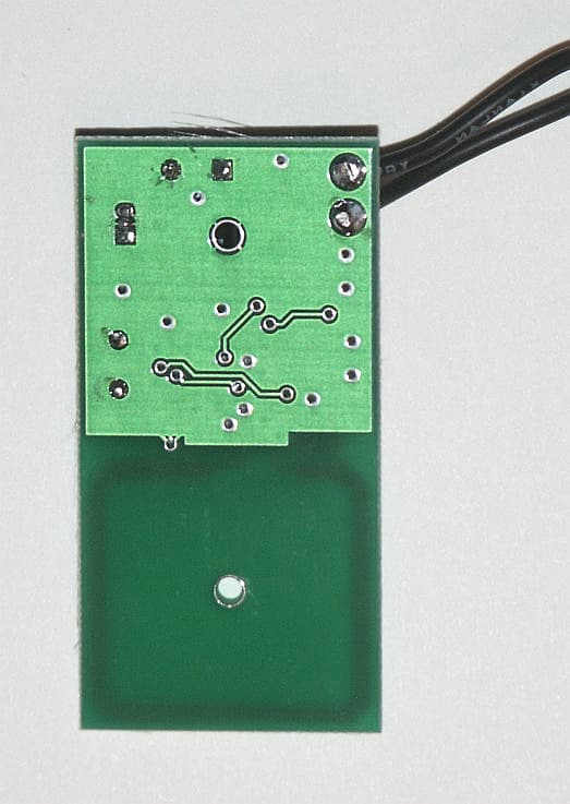
PPCTX02A
Oct 13, 2004Remote Control Transmitter
Equipment Class
DSC - Part 15 Security/Remote Control Transmitter