PPEAC-TXMTransmitter
Nova Solutions, Inc.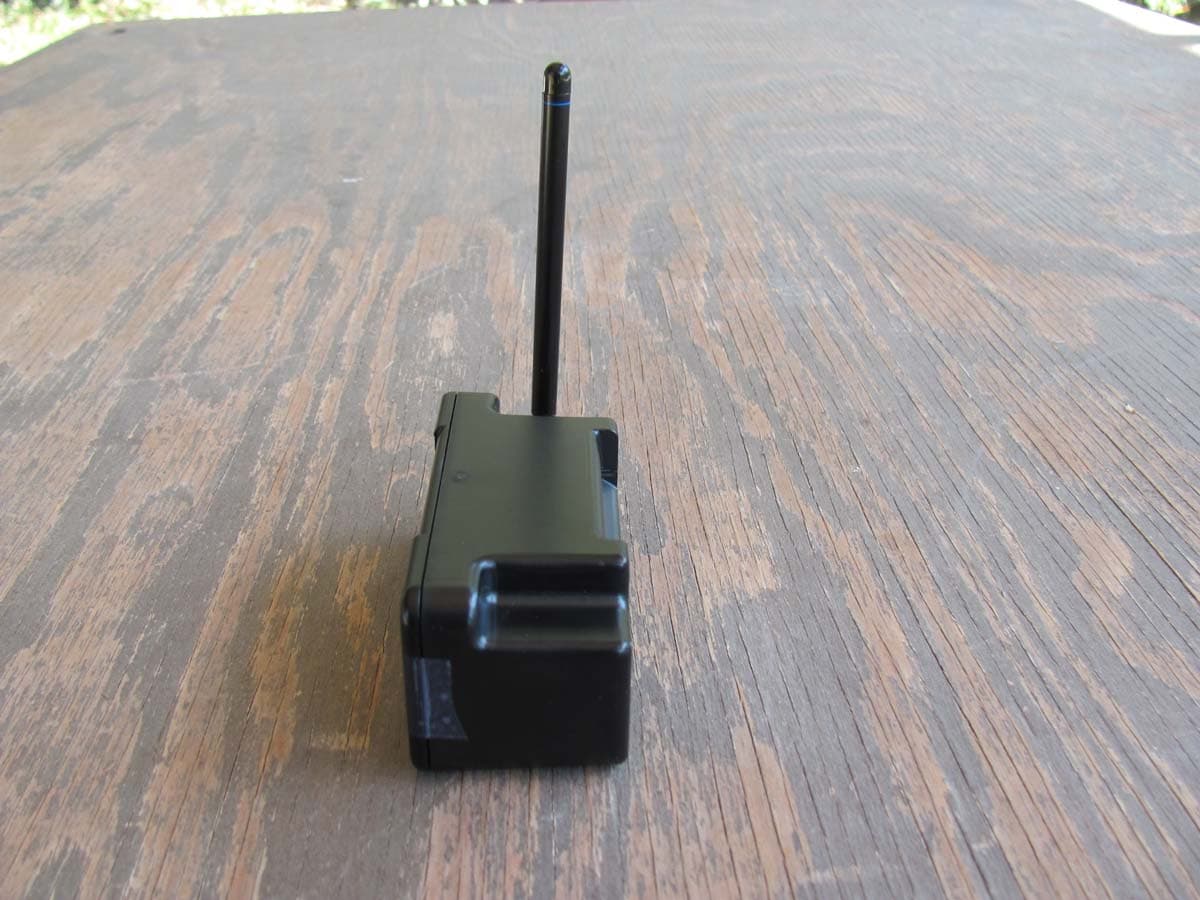
Click to zoom
Application Details
- Equipment Class
- DSC - Part 15 Security/Remote Control Transmitter
- Date of Grant
- Nov 20, 2012
- Application Purpose
- Original Equipment
- Date of Application
- Nov 20, 2012
- Equipment Note
- Transmitter
- Frequency Range
- 418.00000000 - 418.00000000
- Company
- Nova Solutions, Inc.
- Country
- United States
Documents & Files
Document Text
Text extracted from the exhibit documents filed with the FCC. Open a document above to read the original.
Users Manual
© 2012, NOVA Solutions, Inc. NOVALinked_USER_MANUAL 11/12 Linked ™ This equipment has been tested and found to comply with the limits for a class B digital device, pursuant to part 15 of the FCC Rules. These limits are designed to provide reasonable protection against harmful interference in a residential installation. This equipment generates, uses and can radiate radio frequency energy and if not installed and used in accordance with the instructions, may cause harmful interference to radio communications. However, there is no guarantee that interference will not occur in a particular installation. If this equipment does cause harmful interference to radio or television reception, which can be determined by turning the equipment off and on, the user is encouraged to try to correct the interference by one or more of the following measures: * Reorient or relocate the receiving antenna. * Increase the separation between the equipment and receiver. * Connect the equipment into an outlet on a circuit different from that to which the receiver is connected. * Consult the dealer or an experienced radio/TV technician for help. Operation with non-approved equipment is likely to result in interference to radio and TV reception. The user is cautioned that changes and modifications made to the equipment without the approval of manufacturer could void the user’s authority to operate this equipment. • Address bar on the AC-TXM and AC-RCVR provides for 1,204 unique address possibilities. This allows for multiple zones and no interference between classrooms located in close proximity with each other. • Each module is powered by using a 24V power supply. • 418 MHZ AC-TXM sends 4 separate commands: on, off, up, down. This prevents the system from getting out of sync. Address Bar • The AC-TXM and AC-RCVR address bar dip switches must match. Use a pen or screwdriver to gently move switches. • AC-TXM power supply is 24V 1.67 A, 40W with power cord • Connects to major brand controller or NOVA’s Independent Switching Interface (ISI) with standard RJ45 CAT6 patch cables • Mounting bracket included for AC-TXM and AC-RCVR USER MANUAL RF Transmitter, typically located on lectern (Qty 1) Has a unique frequency. AC-TXM Receiver 1 per row (Qty 4) AC-RCVR Independent Switching Interface, typically located on lectern (Qty 1) AC-ISI CAT6 Patch Cable 1ft or 2ft cable needed to run from RCVR to the 1st LCI in each row (Qty 4) AC-CAT6-2 5ft or 7ft cables needed to run from LCI to LCI in each row (Qty 16) AC-CAT6-5 Linking Control Interface 1 per Trolley, except in Lectern when using a CSIM or Transmitter If Lectern utilizes a Trolley with CSIM or Transimitter, then no need for an LCI. (Qty 20) AC-LCI Configuration for Wireless NOVALinked™Control Modules For instructions on programming a controller with the wireless system, see attached. For AC-TXM and AC-RCVR Linked ™ NOVA Solutions, Inc. 421 W. Industrial Avenue Effingham, IL 62401 800-730-6682 • 800-940-6682 (Fax) www.novadesk.com • [email protected] © 2012, NOVA Solutions, Inc. - NLS_INT 11/2012 Integration requirements for control systems INSTRUCTION MANUAL Relay Information Three (3) additional relays are required for the NOVALinked™ option to work properly with a control system. • #1 relay would be programmed as a momentary switch to perform ON and OFF functionality using the RF transmitter and receivers. • #2 relay would be configured as a momentary switch to perform OFF functionality using the RF transmitter and receivers. • #3 relay would be configured as a momentary switch that can be utilized for the UP command. • #4 relay would be configured as a momentary switch that can be utilized for the DOWN command. Control System Programming Menu / Pages You would need an area or preferably a separate page/menu that would be labeled “NOVALinked™”, “Monitors”, or whatever you would prefer to label it. The page would contain the programming which utilizes the 4 additional relays as discussed above. The page/menu would contain two buttons; one as ON or Networked and the second as OFF or Local Control. These buttons would activate and deactivate relay # 1 “ON” and relay #2 “OFF”. In addition, it would also contain one UP button (relay # 3) and one DOWN button (relay # 4). If the ON/Networked button is selected it should change colors to indicated that it is active. When it is active, the local UP and DOWN buttons on the Trolleys “user workstations” will be disabled and the Control system menu/page UP and Down buttons will be active so the Trolleys can only be controlled using the control system menu. As a best practice, when OFF or Manual button is selected then UP and DOWN buttons on this page should be disabled. However, if they are still active in the programming and the user would send an UP or DOWN command to the Trolleys, they will not respond nor will the local buttons be disabled at the “user workstations”. © 2012, NOVA Solutions, Inc. - NLS_INT 11/2012 p. 1 INSTRUCTION MANUAL Linked ™ ON – enables the RF Transmitter/CSIM which establishes communications with the LCI(s) for each Trolley. This locks out the local UP and Down buttons on each of the Trolleys and only allows for control by using the UP and DOWN buttons located on the dedicated page/menu within the control system menu, as discussed above. OFF – Disables the RF Transmitter/CSIM which tells the LCI(s) to release the control back to the local UP and DOWN buttons on each of the Trolleys. Sample Page / Menu Off or Local Control (Mode): The Up and Down functions will no longer work from the control system page/menu and should be disabled in the programming. The Up and Down func- tions for each Trolley can only be controlled at the local workstation. On or Networked (Mode): The Up and Down functions are enabled in the programming when in the ON/Networked state. Users will now be able to control the Trolleys on the control sys- tem page/menu and local UP and DOWN buttons will be disabled on all Trolleys …
Text truncated - open the document above for the full version.
Attestation Statements
NOVA Solutions, Inc. 421 W. Industrial Avenue Effingham, IL 62401 PHONE 800-730-6682 FAX 800-940-6682 EMAIL [email protected] WEB www.novadesk.com www.novadesk.com October 11, 2012 CETCB 114 Olinda Drive Brea, CA 92823 Gentlemen: This is a letter of authorization to accept Compatible Electronics, Inc., specifically including the employees of Compatible Electronics, as an Agent for NOVA Solutions, Inc, 421 W. Industrial Avenue Effingham, IL, for a period of one year, to sign applications before the Commission on our behalf, to make representations to you on our behalf, and to receive and exchange data between our company and the Commission in connection with certification of the following NOVA Solutions, Inc. product: Transmitters & Receivers Under FCC Docket Number 20780 and General Docket Number 80-284 pursuant to Part l5 of FCC Rules and Regulations. Please also accept this letter as an attestation that neither NOVA Solutions, Inc. nor any of its officers, directors, or persons holding 5% or more of the outstanding stock or shares, voting or non-voting, have been denied federal benefits under section 5301 of the Anti-Drug-Abuse act of 1988,21 U.S.C. 853(a). In addition, NOVA Solutions, Inc. will notify the Federal Communications Commission if, at any time, the situation changes causing NOVA Solutions, Inc. to be denied federal benefits. If you have any further questions or need additional information, please feel free to give me a call at 800-730-6682. Sincerely, John Lechman President and CEO
Attestation Statements
NOVA Solutions, Inc. 421 W. Industrial Avenue Effingham, IL 62401 PHONE 800-730-6682 FAX 800-940-6682 EMAIL [email protected] WEB www.novadesk.com www.novadesk.com October 12, 2012 Compatible Electronics TCB 114 Olinda Drive Brea, California 92823 Subject: TCB application submittal Gentlemen: We, NOVA Solutions, Inc., would like to declare that the application being submitted for the device with FCC ID: PPEAC-TXM has not been submitted to another TCB or FCC for certification. If you have any questions, please do not hesitate to contact us at 800-730-6682. Sincerely, John Lechman President and CEO
Attestation Statements
NOVA Solutions, Inc. 421 W. Industrial Avenue Effingham, IL 62401 PHONE 800-730-6682 FAX 800-940-6682 EMAIL [email protected] WEB www.novadesk.com www.novadesk.com October 15, 2012 CETCB 114 Olinda Drive Brea, CA 92823 Gentlemen: This letter is to formally notify you that the following modification(s) had been completed by Compatible Electronics, Inc. to our Transmitter AC-TXM during FCC certification, and will be implemented in production. R7 was changed to 820 ohms. Sincerely, John Lechman President and CEO
ID Label/Location Info
2” W x 1”H Location of label on transmitter FCC ID: PPEAC-TXM This device complies with Part 15 of the FCC Rules. Operation is subject to the following two conditions: (1) This device may not cause harmful interference and (2) this device must accept any interference received, including interference that may cause undesired operation. FCC ID: PPEAC-TXM This device complies with Part 15 of the FCC Rules. Operation is subject to the following two conditions: (1) This device may not cause harmful interference and (2) this device must accept any interference received, including interference that may cause undesired operation.
Test Report
Report Number: B20907B1 FCC Part 15 Subpart B and C, Section 15.205, 15.209 and 15.231 Test Report Transmitter Model: AC-TXM Brea Division 114 Olinda Drive Brea, CA 92823 (714) 579-0500 Agoura Division 2337 Troutdale Drive Agoura, CA 91301 (818) 597-0600 Silverado Division 19121 El Toro Road Silverado, CA 92676 (949) 589-0700 Lake Forest Division 20621 Pascal Way Lake Forest, CA 92630 (949) 587-0400 Page 1 of 17 FCC PART 15 SUBPART B and C TEST REPORT for TRANSMITTER MODEL: AC-TXM Prepared for NOVA SOLUTIONS, INC. 421 WEST INDUSTRIAL AVENUE EFFINGHAM, ILLINOIS 62401 Prepared by:_____________________ KYLE FUJIMOTO Approved by:____________________ JAMES ROSS COMPATIBLE ELECTRONICS INC. 114 OLINDA DRIVE BREA, CALIFORNIA 92823 (714) 579-0500 DATE: SEPTEMBER 7, 2012 REPORT APPENDICES TOTAL BODY A B C D E PAGES 17 2 2 2 12 21 56 This report shall not be reproduced except in full, without the written approval of Compatible Electronics. Report Number: B20907B1 FCC Part 15 Subpart B and C, Section 15.205, 15.209 and 15.231 Test Report Transmitter Model: AC-TXM Brea Division 114 Olinda Drive Brea, CA 92823 (714) 579-0500 Agoura Division 2337 Troutdale Drive Agoura, CA 91301 (818) 597-0600 Silverado Division 19121 El Toro Road Silverado, CA 92676 (949) 589-0700 Lake Forest Division 20621 Pascal Way Lake Forest, CA 92630 (949) 587-0400 Page 2 of 17 TABLE OF CONTENTS Section / Title PAGE GENERAL REPORT SUMMARY 4 SUMMARY OF TEST RESULTS 4 1. PURPOSE 5 2. ADMINISTRATIVE DATA 6 2.1 Location of Testing 6 2.2 Traceability Statement 6 2.3 Cognizant Personnel 6 2.4 Date Test Sample was Received 6 2.5 Disposition of the Test Sample 6 2.6 Abbreviations and Acronyms 6 3. APPLICABLE DOCUMENTS 7 4. DESCRIPTION OF TEST CONFIGURATION 8 4.1 Description of Test Configuration – Emissions 8 4.1.1 Cable Construction and Termination 8 5. LISTS OF EUT, ACCESSORIES AND TEST EQUIPMENT 9 5.1 EUT and Accessory List 9 5.2 Emissions Test Equipment 10 6. TEST SITE DESCRIPTION 11 6.1 Test Facility Description 11 6.2 EUT Mounting, Bonding and Grounding 11 6.3 Facility Environmental Characteristics 11 7. TEST PROCEDURES 12 7.1 RF Emissions 12 7.1.1 Conducted Emissions Test 12 7.1.2 Radiated Emissions (Spurious and Harmonics) Test 13 7.1.3 RF Emissions Test Results 15 8. CONCLUSIONS 17 Report Number: B20907B1 FCC Part 15 Subpart B and C, Section 15.205, 15.209 and 15.231 Test Report Transmitter Model: AC-TXM Brea Division 114 Olinda Drive Brea, CA 92823 (714) 579-0500 Agoura Division 2337 Troutdale Drive Agoura, CA 91301 (818) 597-0600 Silverado Division 19121 El Toro Road Silverado, CA 92676 (949) 589-0700 Lake Forest Division 20621 Pascal Way Lake Forest, CA 92630 (949) 587-0400 Page 3 of 17 LIST OF APPENDICES APPENDIX TITLE A Laboratory Accreditations and Recognitions B Modifications to the EUT C Additional Models Covered Under This Report D Diagram, Charts, and Photos Test Setup Diagram Antenna and Amplifier Factors Radiated Emissions Photos E Data Sheets LIST OF FIGURES FIGURE TITLE 1 Conducted Emissions Test Setup 2 Plot Map And Layout of Radiated Test Site – 3 Meters Report Number: B20907B1 FCC Part 15 Subpart B and C, Section 15.205, 15.209 and 15.231 Test Report Transmitter Model: AC-TXM Brea Division 114 Olinda Drive Brea, CA 92823 (714) 579-0500 Agoura Division 2337 Troutdale Drive Agoura, CA 91301 (818) 597-0600 Silverado Division 19121 El Toro Road Silverado, CA 92676 (949) 589-0700 Lake Forest Division 20621 Pascal Way Lake Forest, CA 92630 (949) 587-0400 Page 4 of 17 GENERAL REPORT SUMMARY Compatible Electronics Inc. generates this electromagnetic emission test report, which is an independent testing and consulting firm. The test report is based on testing performed by Compatible Electronics personnel according to the measurement procedures described in the test specifications given below and in the "Test Procedures" section of this report. The measurement data and conclusions appearing herein relate only to the sample tested and this report may not be reproduced without the written permission of Compatible Electronics, unless done so in full. This report must not be used to claim product endorsement by NVLAP, NIST or any other agency of the U.S. Government. Device Tested: Transmitter Model: AC-TXM S/N: N/A Product Description: See Expository Statement Modifications: The EUT was not modified in order to meet the specifications. Customer: Nova Solutions, Inc. 421 West Industrial Avenue Effingham, Illinois 62401 Test Date(s): September 7, 2012 Test Specifications: Emissions requirements CFR Title 47, Part 15, Subpart B and Subpart C, Sections 15.205, 15.209, and 15.231 Test Procedure: ANSI C63.4 Test Deviations: The test procedure was not deviated from during the testing. SUMMARY OF TEST RESULTS TEST DESCRIPTION RESULTS 1 Conducted RF Emissions 150 kHz to 30 MHz Complies with the Class B limits of CFR Title 47, Part 15, Subpart B; and Subpart C, section 15.207 2 Radiated RF Emissions 10 kHz to 4180 MHz (Transmitter and Digital Portion) Complies with the Class B limits of CFR Title 47, Part 15, Subpart B; and Subpart C, sections 15.205, 15.209, and 15.231. Report Number: B20907B1 FCC Part 15 Subpart B and C, Section 15.205, 15.209 and 15.231 Test Report Transmitter Model: AC-TXM Brea Division 114 Olinda Drive Brea, CA 92823 (714) 579-0500 Agoura Division 2337 Troutdale Drive Agoura, CA 91301 (818) 597-0600 Silverado Division 19121 El Toro Road Silverado, CA 92676 (949) 589-0700 Lake Forest Division 20621 Pascal Way Lake Forest, CA 92630 (949) 587-0400 Page 5 of 17 1. PURPOSE This document is a qualification test report based on the Electromagnetic Interference (EMI) tests performed on the Transmitter, Model: AC-TXM. The Emissions measurements were performed according to the measurement procedure described in ANSI C63.4. The tests were performed in order to determine whether the electromagnetic emissions from the equipment under test, referred to as EUT hereafter, are within the Class B specification limits defined…
Text truncated - open the document above for the full version.
Test Report
Ref Lvl 92 dB V Ref Lvl 92 dB V RF Att 10 dB A Unit dB V P0 TDS SWT 200 ms Center 417.9549098 MHz20 ms/ 1VIEW D1 5 1AP RBW 1 MHz VBW 3 MHz IN1 * 0 10 20 30 40 50 60 70 80 -8 92 1 1 Delta 1 [T1] -1.06 dB 68.136273 ms 1 [T1] 18.85 dB V 49.699399 ms 1 [T1] -1.06 dB 68.136273 ms D1 58.64 dB V D2 54 dB V Date: 7.SEP.2012 08:15:01 Time of Pulse with Blanking Interval = 68.136273 mS Ref Lvl 92 dB V Ref Lvl 92 dB V RF Att 10 dB A Unit dB V RBW 1 MHz VBW 3 MHz IN1 P0 TDS SWT 5 ms Center 417.9549098 MHz500 s/ 1VIEW1AP 0 10 20 30 40 50 60 70 80 -8 92 1 1 Delta 1 [T1] -0.08 dB 430.861723 s 1 [T1] 48.78 dB V 470.941884 s 1 [T1] -0.08 dB 430.861723 s Date: 7.SEP.2012 08:31:35 Time of One Small Pulse = 430.861723 uS Ref Lvl 92 dB V Ref Lvl 92 dB V RF Att 10 dB A Unit dB V RBW 1 MHz VBW 3 MHz IN1 P0 TDS SWT 5 ms Center 417.9549098 MHz500 s/ 1VIEW1AP 0 10 20 30 40 50 60 70 80 -8 92 1 1 Delta 1 [T1] 1.58 dB 881.763527 s 1 [T1] 41.58 dB V 3.937876 ms 1 [T1] 1.58 dB 881.763527 s Date: 7.SEP.2012 08:32:56 Time of One Large Pulse = 881.763527 uS Ref Lvl 92 dB V Ref Lvl 92 dB V RF Att 10 dB A Unit dB V RBW 1 MHz VBW 3 MHz IN1 SWT 100 ms Center 417.9549098 MHz10 ms/ P0 TDS 1VIEW1AP 0 10 20 30 40 50 60 70 80 -8 92 1 1 Delta 1 [T1] 0.29 dB 65.330661 ms 1 [T1] 25.65 dB V 5.210421 ms 1 [T1] 0.29 dB 65.330661 ms Date: 7.SEP.2012 08:22:27 Number of Small Pulses = 13 * 430.861723 uS = 5.601202399 mS Number of Large Pulses = 28 * 881.763527 uS = 24.689378756 mS Total Duty Cycle = 30.290581155 mS / 68.136273 mS = 44.46% Peak to Average Ratio = -7.04 dB
Test Report
Ref Lvl 100 dB V Ref Lvl 100 dB V RBW 100 kHz VBW 300 kHz RF Att 10 dB 8 dB Offset D19515dB V A IN1 Unit dB V P0 TDS SWT 5 s Center 417.98998 MHz500 ms/ 1VIEW1AP * 10 20 30 40 50 60 70 80 90 0 100 1 1 Delta 1 [T1] 0.60 dB 3.316633 s 1 [T1] 28.48 dB V 561.122244 ms 1 [T1] 0.60 dB 3.316633 s D1 95.15 dB V Date: 10.SEP.2012 14:44:17 5 Second Rule – The Transmitter shuts off within 5 seconds of being activated
Test Report
HOW THE EUT MEETS THE REQUIREMENTS OF 15.31 (e) FOR THE NOVA SOLUTIONS, INC. TRANSMITTER, MODEL: AC-TXM The fundamental was maximized on the Lab A test site using a normal test setup with the AC adapter for the EUT connected directly to the AC public mains (115 Vac). Next, the AC adapter for the EUT was then connected to the Staco Energy Products Variable Auto Transformer Model: 3PN1010. The Variable Auto Transformer allows the Vac input to be varied. The AC input was then dropped to 85% (97.75 Vac) and raised to 115% (132.25 Vac). The actual AC input was measured using a calibrated Wavetek Multimeter Model: DM25XT, Serial Number: 40209875, Calibration Due Date: May 30, 2013. The fundamental was then verified again to see that the amplitude did not change. Test Result: The EUT does NOT change amplitude at the fundamental when the AC input voltage is varied between 85% and 115% of the input nominal rated supply voltage.
Contact Information
Applicant
John N Lechman(President)
Technical Contact
Compatible Electronics, Inc.Kyle Fujimoto
[email protected]714-579-0500
114 Olinda Drive · Brea, California · United States
Test Firm
Compatible Electronics, Inc.Michael Christensen
Technical Specifications
| # | Rule Parts | Frequency Range | Power Output |
|---|---|---|---|
| 1 | 15.231 | 418 MHz - 418 MHz | - |