PPGCPI2001Wireless RF HandFree EarPhone
Cyber Pacific (Hong Kong) Limited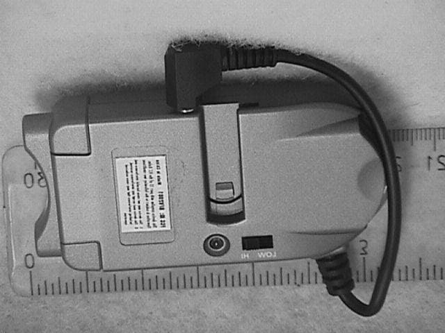
Click to zoom
Application Details
- Equipment Class
- DXT - Part 15 Low Power Transceiver, Rx Verified
- Date of Grant
- Jul 01, 2001
- Application Purpose
- Original Equipment
- Date of Application
- Jul 01, 2001
- Equipment Note
- Wireless RF HandFree EarPhone
- Frequency Range
- 397.60000000 - 398.80000000
- Country
- China
Documents & Files
Document Text
Text extracted from the exhibit documents filed with the FCC. Open a document above to read the original.
Users Manual
1 APPENDIX B OPERATION INSTRUCTION 1. System introduction The system consists of one transceiver. One ear-piece, one plastic case, one charger (including two pieces of Lithium-Ion batteries) and one AC/DC adapter. The system utilizes state of the art wireless communication technology to achieve a high- quality replacement of the usual wired headset. The ease of use and the extremely low radiation power (less than 0.01mW) of the transceiver and the ear-piece, make the system ideal for daily usage. 2. OPERATION a. Connect the transceiver to your cellular phone by plugging the 2.5mm jack into the phone’s headphone outlet. In case your cellular phone has a different type of headphone outlet, please use a converter (not included) which has an access to the 2.5mm jack. b. Load the fully charged batteries into the battery compartments of the transceiver and ear-piece. Make sure the positive sign face down on the battery ring. c. The system is now in stand by mode. Observe that the LED in the transceiver blinks intermittently at an approximate interval of 4 seconds. d. There are two ways that the system will enter the operation state. To enter operation state manually, press the on/off switch on the ear-piece and a single beep will sound immediately in response. To enter operation state automatically, nothing needs to be done. Notice that there are two beeps in the ear-piece to signify the transition from stand by to operation. One can test the automatic operation by just pressing the keyboard on the cellular phone. Depending on manufacturers of cellular phones, one may hear the keyboard beep through the ear-piece. In any case, when your telephone is connected (whether dial out or dial in), the system will operate automatically and you can hear and talk freely. e. If your cellular phone has voice dialing feature, you can use the wireless headset to perform this function. Simply press the on/off switch on the ear-piece and then choose the voice dialing command in the cellular phone, talk just as you would with the cellular phone only. f. When battery voltage is low in either the transceiver or ear-piece, you can hear several warning beeps. After the beeps, the system will still operate for a few minutes, and then stops operate completely. At this stage, the LED of the transceiver will stop blinking and the ON/OFF switch in the ear-piece will stop working. In this case, please recharge the battery. g. Usage of ear-piece on/off switch 2 The switch has dual function of on/off and volume adjustment. Please note following steps: a) Single press with one ‘BEEP-TONE’ is to operate the system . b) During conservation, each press will allow you to hear a single ‘BEEP’ and that is to change the volume. There are three volume level that you can choose and each beep indicate the next volume level. Once it reaches the highest level, each press will decrement to the next lower level and when it reaches the lowest level, each press will increment to the next higher level. c) To enter the standby mode manually, you can press the switch firmly for 2 seconds. At this moment, two ‘BEEP-TONE’ can be heard. It is recommended that the system should be manually set to standby mode for conserving power. h. Automatic standby mode after use After 30 seconds up to one minute of silence in the phone, the system will enter standby mode automatically to conserve power. i. LED and switch in transceiver *LED The LED blinks approximately at 4-seconds interval during operation. *Hi-Low volume switch There is a Hi-Low volume setting with the mini transceiver. This provides a convenience for the transceiver to adapt to different sound level of different phone makers. j. Out of Range When ear-piece is out of range from transceiver, static noise will increase suddenly, the user should go back near the transceiver. In some models, there may be a warning beep to indicate this situation. 3. Recharging System provides a charger which allows two lithium-Ion batteries to be charged at the same time. a. Install the plug of AC adapter to the DC jack of the unit and plug the adapter into a standard wall outlet . The multi-color LED is displaying green when charger is ready. b. Insert the battery into the charger together with the battery ‘ring’ and matching polarity. The LED will illuminate red to show that charging is taking place. c. LED will glow amber when battery capacity reaches 90%. The battery will be fully charged in approximately one hour by then and LED will turn green. d. Unplug the AC adapter and it is safe to keep the batteries inside the charger when not in use. e. Please pay attention to the local voltage when you use the adapter f. Avoid leaving the batteries in the ear-piece or transceiver for more than 7 days without recharge. It is better to leave the batteries inside the charger when not in use. 4. Things to beware of when system is not functioning. 3 a. Is on/off button switched off? b. Is there any battery loaded in? c. Is battery fully recharged? d. Is transceiver properly connected to cellular phone? e. Is transceiver loaded with fully recharged battery? f. Is ear-piece out of transmit/receive range? g. Is battery properly in place without mixing up positive and negative side? h. Is LED in transceiver still blinking? 5. Features: a. Extremely low output power creating no radiation hazards. b. Standby time: 80 hours. c. Continuous talk time 2 hours. d. Full duplex. e. Used with any cellular phone, home phone. f. Replaceable batteries. g. Automatic anti-collusion system to avoid cross talking with other users within the same working radius. h. Maximum 5 channels and 65000 address codes to avoid interference with other users. i. Very low static noise and high fidelity sound. j. State of the art microwave wireless technology.
Operational Description
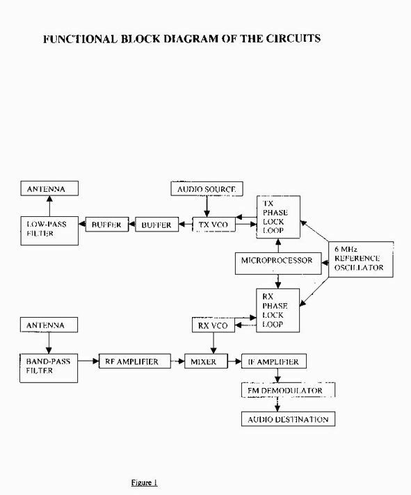
1 Functional Description of Wireless Headset 1.0 Introduction The Wireless Headset consists of three functional entities which are described as the Base, Head- piece and Charger. The Base and the Head-piece are basically transceivers that provide a short-range wireless duplex audio link between a cellular phone and the Head-piece. The Head-piece basically contains a microphone and a speaker that replace the build-in microphone and speaker of the cellular phone in a wireless fashion. Detail operation instruction can be found in Appendix B. 2.0 Theory of operation The Base and Head-piece communicate in frequency-division-duplex (FDD) fashion to establish a two-way voice link between the base and head-piece. The up-link and down-link frequency bands are chosen between 300Mhz to 450Mhz. The bands are chosen to be 40Mhz apart minimally and the channel band-width is minimum 200Khz. The RF circuits of the Base and Head-piece are identical and the following description of the receive and transmit circuits apply to both. Refer to figure 1 which is the functional block diagram of the circuits. In the transmit circuit, a voltage control oscillator (VCO) and a phase lock loop is used to synthesize the transmit frequency. This synthesizer is programmed by the microprocessor and they both share a common 6MHz reference oscillator. The VCO is frequency modulated by the incoming audio source and also by the microprocessor. The synthesizer feeds its output to two stages of buffers and is low-pass filtered by a series of LC. The signal is then output to the transmit antenna. A helical antenna is used in the Base and a monopole antenna is used in the Head-piece. In the receive circuit, the same type of synthesizer as used in the transmit circuit is employed to create the local oscillator needed for ordinary super- heterodyne receiver. Signal comes from the receive antenna which is then fed to SAW band-pass filter. The filtered signal then goes through the RF amplifier and then to the mixer which down converts the RF signal to an intermediate frequency. The IF is 10.7Mhz and this IF signal is directly amplified and frequency-demodulated. The audio signal is then fed to an amplifier and then output to the audio destination. 3.0 Circuit schematic description BASE circuit : Refer to appendix A, circuit schematic with title ‘MIC BASE’. The microprocessor is IC3 and the RX and TX phase lock loops are contained in IC2. The 6Mhz reference oscillator is a crystal oscillator implemented with the internal circuitry of the microprocessor. The RX VCO contains Q5 and varactor diode D2. The TX VCO contains Q4 and varactor diode D1. The transmit buffers is composed of Q2 and Q3. Q7 is the RF amplifier and the MIXER, IF AMPLIFIER and FM-DEMODULATOR are all contained in IC4. The audio source and audio destination is the cellular phone’s 2.5mm socket which is the speaker output and microphone input. Q6 provides a voltage indicator which switches collector output to high whenever battery voltage drops below 3.0 volts with tolerance of -0.2 volt. At this level the microprocessor will switch off all circuitry. IC1 is a low-drop voltage regulator which outputs 2.5volt with 0.2volt threshold. HEAD-PIECE circuit: Refer to appendix A, circuit schematic with title ‘MIC HEADSET’. The microprocessor is IC3 and the RX and TX phase lock loops are contained in IC2. The 6Mhz reference oscillator is a crystal oscillator implemented with the internal circuitry of the microprocessor. The RX VCO contains Q5 and varactor diode D2. The TX VCO contains Q4 and varactor diode D1. The transmit buffers is composed of Q2 and Q3. Q7 is the RF amplifier and the MIXER, IF AMPLIFIER and FM- DEMODULATOR are all contained in IC5. The audio source is the amplified microphone signal, and the audio destination is the audio amplifier IC6 and speaker SP1. Q6 provides a voltage indicator which switches collector output to high whenever battery voltage drops below 3.0 volts with tolerance of -0.2 2 volt. At this level the microprocessor will switch off all circuitry. IC1 is a low-drop voltage regulator which outputs 2.5volt at 0.2volt threshold. 4.0 Specifications Transmission: BASE HEAD-PIECE UNIT Frequency: 300<bf<450 bf+40 MHz Frequency stability: +/-50 +/-50 ppm (at extreme temperature) Channels: 5 5 Channel separation: >200 >200 KHz Terminal output power -35 -35 dbm Reception: Frequency: hf-40 300<hf<450 MHz Frequency stability: +/-50 +/-50 ppm (at extreme temperature) Channels: 5 5 Channel separation: >200 >200 KHz Receiver type: ----- super-heterodyne ------ Intermediate frequency: 10.7 10.7 MHz General: Working voltage: 3.0-6.0 3.0-6.0 volt Current consumption: 26 29 ma Battery voltage: (fully charged) 4.2 4.2 volt (stop-working) 3.0 3.0 volt Software: Version number is 3.0. FREQUENCY TABLE (in MHz) BASE HEAD-PIECE CHANNEL TX RX TX RX 1 397.6 447.2 447.2 397.6 2 397.9 447.5 447.5 397.9 3 398.2 447.8 447.8 398.2 4 398.5 448.1 448.1 398.5 5 398.8 448.4 448.4 398.8 3 Figure 1 BUFFER BUFFER ANTENNA TX PHASE LOCK LOOP MICROPROCESSOR TX VCO AUDIO SOURCE ANTENNA RF AMPLIFIER MIXER RX VCO RX PHASE LOCK LOOP IF AMPLIFIER FM DEMODULATOR AUDIO DESTINATION LOW-PASS FILTER BAND-PASS FILTER 6 MHz REFERENCE OSCILLATOR
Schematics
SCHEMATIC DIAGRAM OF MIC BASE
Test Report
APPLICANT Cyber Pacific (Hong Kong) Limited 3808 38/F West Tower Shun Tak Centre, 168-200 Connaught Road Central, Hong Kong, China MANUFACTURER Golden Eagle Electronics Manufactory LTD. Suite 215, 2/F., New East Ocean Centre 9 Science Museum Road Tsim Sha Tsui East, Kowloon Hong Kong, China TEST SPECIFICATION: FCC Rules and Regulations Part 15, Subpart C TEST PROCEDURE: FCC 15.209(a) TEST SAMPLE DESCRIPTION BRANDNAME: Com-Talk MODEL: GEMC2001 FCC ID: PPGCPI2001 TYPE: Hands Free Base Transmitter FREQUENCY RANGE: 397.6, 397.9, 398.2, 398.5, 398.8 MHz POWER REQUIREMENTS: 3.6 VDC derived from a rechargeable battery TESTS PERFORMED - 15.209 Radiated Emissions REPORT OF MEASUREMENTS Applicant: Cyber Pacific (Hong Kong) Limited Device: Hands Free Base Transmitter FCC ID: PPGCPI2001 Power Requirements: 3.6 VDC derived from a rechargeable battery Applicable Rule Section: Part 15, Subpart C, Section 15.209 Report Number: R-8976-1 FCC ID #: PPGCPI2001 TEST RESULTS 15.203:The intentional radiator is designed to ensure that no antenna other than that furnished by the applicant can be used with the device. 15.209(c):Emissions radiated were attenuated in accordance with the general radiated emissions limits of 15.209. GENERAL NOTES 1.All user accessible controls were adjusted to produce maximum emissions. 2.The frequency range was scanned from 30MHz to 4.5 GHz. All emissions not reported were more than 20dB below the specified limit. Report Number: R-8976-1 FCC ID #: PPGCPI2001 EXHIBIT 4 Radiated Emissions, Spurious Emissions Para. 15.209(a) (Please see separate e-file attachment named REspur.pdf) Report Number: R-8976-1 FCC ID #: PPGCPI2001 EQUIPMENT LIST FCC15.209(a) Radiated Emissions, 30MHz-4GHz ENTypeManufacturerDescriptionModel No.Cal DateDue Date 067Open Area Test SiteRetlif3 MeterRNY10/15/200010/15/2003 128CDouble Ridge GuideEaton Corporation1 GHz - 18 GHz9600109/18/200009/18/2001 133Broadband Pre-AmplifierElectro-Metrics10 kHz - 1 GHz, 26dBBPA-100006/13/200006/13/2001 141Spectrum AnalyzerHewlett Packard100 Hz - 40 GHz8566B08/03/200002/03/2001 141AGraphics PlotterHewlett PackardN/A7470A03/08/200003/08/2001 141BQuasi-Peak AdaptorHewlett Packard100 Hz - 1 GHz85650A08/02/200002/02/2001 206B6.0 dB AttenuatorTexscan0 - 1.0 GHzFP-50 - 6 dB06/13/200006/13/2001 523BiconilogElectro-Mechanics26 - 2000 MHz3142B06/08/200006/08/2001 543PreamplifierHewlett Packard1.0 GHz - 26.5 GHz8449B06/16/199906/16/2001 617Interference AnalyzerElectro-Metrics10 kHz - 1 GHzEMC-3001/17/200001/17/2001 Report Number: R-8976-1 FCC ID #: PPGCPI2001 Retlif Testing Laboratories R Retlif Job Number R-8976-1 Data Sheet 1 of 1 Test Method: FCC Part 15 Subpart C, Spurious Case Radiated Emissions, Paragraph 15.209(a) Customer: Golden Eagle Electronics Manufactory Ltd. Job No. R-8976-1 Test Sample: Hands Free Base 398.8 MHz FM Transmitter Model No.: GEMC2001 FCC ID: PPGCPI2001 Operating Mode: Continuously Transmitting a 398.8 MHz CW signal. Technician: Peter Lananna Date: December 21, 2000 Notes: Test Distance: 3 Meters Temp:4C Humidity:53% Detector: Quasi-Peak 30 MHz to 1 GHz, Peak above 1 GHz Test Freq. Antenna Position EUT Orientation Meter Readings Correction Factor Corrected Reading Converted Reading LIMIT MHz (V/H) / Meters Degrees dBuV dB dBuV/m uV/m uV/m 30.00 100 | | | | | | | | | | | | 88.00 100 88.00 150 l | | | | | | | | | | | | | l | 216.00 150 216.00 200 | | 398.8 V/1.3 248 46 -1.3 44.7 171.8 | l | 960.00 200 960.00 500 l | | | l | 4000.0 500 The EUT was scanned from 30 MHz to 4 GHz The emissions observed from the EUT do not exceed the specified limits. Emissions not recorded were more than 10dB under the specified limit Retlif Testing Laboratories R Retlif Job Number R-8976-1 Data Sheet 1 of 1 Test Method: FCC Part 15 Subpart C, Spurious Case Radiated Emissions, Paragraph 15.209(a) Customer: Golden Eagle Electronics Manufactory Ltd. Job No. R-8976-1 Test Sample: Hands Free Base 397.6 MHz FM Transmitter Model No.: GEMC2001 FCC ID: PPGCPI2001 Operating Mode: Continuously Transmitting a 397.6 MHz CW signal. Technician: Peter Lananna Date: January 2, 2001 Notes: Test Distance: 3 Meters Temp:4C Humidity:53% Detector: Quasi-Peak 30 MHz to 1 GHz, Peak above 1 GHz Test Freq. Antenna Position EUT Orientation Meter Readings Correction Factor Corrected Reading Converted Reading LIMIT MHz (V/H) / Meters Degrees dBuV dB dBuV/m uV/m uV/m 30.00 100 | | | | | | | | | | | | 88.00 100 88.00 150 l | | | | | | | | | | | | | l | 216.00 150 216.00 200 | | 397.6 V/1.0 203 40 -0.7 39.3 92.2 | l | 960.00 200 960.00 500 l | | | l | 4000.0 500 The EUT was scanned from 30 MHz to 4 GHz The emissions observed from the EUT do exceed the specified limits. Emissions not recorded were more than 10dB under the specified limit
Contact Information
Applicant
Dominic Wong(Vice President)
Technical Contact
Retlif Testing LaboratoriesThomas J Schneider
[email protected]1 631 737 1500
795 Marconi Avenue · Ronkonkoma, New York · United States
Non-Technical Contact
Retlif Testing LaboratoriesMichelle White
[email protected]1 631 737 1500
Test Firm
Retlif Testing LaboratoriesMichael Bozza
Technical Specifications
| # | Rule Parts | Frequency Range | Power Output |
|---|---|---|---|
| 1 | 15C | 397.6 MHz - 398.8 MHz | - |
Other Applications from Cyber Pacific (Hong Kong) Limited
PPGCPI900R
Jun 03, 2002Wireless Headset Transceiver
Equipment Class
DXT - Part 15 Low Power Transceiver, Rx Verified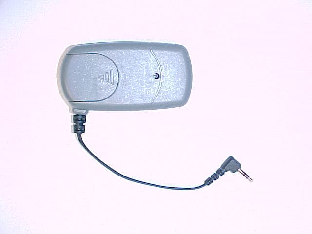
PPGCPI900T
Jun 03, 2002Wireless Headset Base Transceiver
Equipment Class
DXT - Part 15 Low Power Transceiver, Rx Verified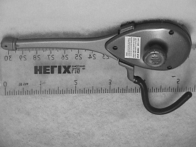
PPGCPI2101
Jul 01, 2001Wireless RF HandFree EarPhone
Equipment Class
DXT - Part 15 Low Power Transceiver, Rx Verified