PPH0TXD20A0Tracktronic
Sauer-Danfoss Ltd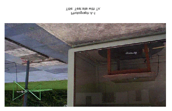
Click to zoom
Application Details
- Equipment Class
- DXX - Part 15 Low Power Communication Device Transmitter
- Date of Grant
- Jul 15, 2001
- Application Purpose
- Original Equipment
- Date of Application
- Jun 28, 2001
- Equipment Note
- Tracktronic
- Frequency Range
- 914.50000000 - 914.50000000
- Company
- Sauer-Danfoss Ltd
- Country
- United Kingdom
Documents & Files
Document Text
Text extracted from the exhibit documents filed with the FCC. Open a document above to read the original.
Users Manual
Traktronic Radio Remote Control System Installation and Fault Diagnosis. Version Date Comments 1.0 03/12/98 Original 2.0 26/06/00. Revision 3.0 10/07/00 Addition of Appendix 1 4.0 14/07/00 Technical revision 4.1 05/01/01 Text Update 4.2 06/06/01 Update to installation detail to include fuse. 4.3 12/06/01 Update to include Battery Caution. 4.4 18/06/01 Update to include Changes Caution. Contents. 1. INTRODUCTION..........................................................................................................................2 2. INSTALLATION OF THE RADIO RECEIVER AERIAL BUFFER......................................2 3. INSTALLATION OF THE RECEIVER DRIVER MODULE..................................................3 4. OPERATION OF THE RADIO TRANSMITTER.....................................................................4 4.1 T URN ON THE R ADIO T RANSMITTER ..........................................................................................4 4.2 A UXILIARY FUNCTION CONTROL ON THE R ADIO T RANSMITTER . ...............................................4 4.3 F EEDER CONTROL ON THE R ADIO T RANSMITTER .......................................................................4 4.4 T RACK O PERATION ON THE R ADIO T RANSMITTER . ...................................................................5 4.5 T URNING O FF THE R ADIO T RANSMITTER . .................................................................................5 4.6 R EPLACEMENT OF THE R ADIO T RANSMITTER B ATTERY . ...........................................................6 5. PROGRAM THE RECEIVER TO OPERATE WITH A SPECIFIC TRANSMITTER........6 6. SET UP THE “SLOW” TRACK SPEEDS ON THE RECEIVER............................................7 7. FAULT DIAGNOSIS.....................................................................................................................8 7.1 F AULT D IAGNOSIS OF THE R ADIO TRANSMITTER . ......................................................................8 7.2 F AULT D IAGNOSIS OF THE R ECEIVER D RIVER M ODULE . ...........................................................9 7.3 F AULT D IAGNOSIS OF THE T RACK C ONTROL OF R ECEIVER D RIVER M ODULE . ........................10 8. APPENDIX 1. MACHINE FAULT FINDING CHECKLIST.................................................11 9 APPENDIX 2 INSTALLATION WIRING DIAGRAM...........................................................12 Page 1 of 14 CAUTION: Risk of explosion if battery is replaced incorrectly or by incorrect type. Dispose of used batteries according to local guidelines. CAUTION: Changes or modifications not expressly approved by the manufacture could void the user’s authority to operate the equipment and would void any warranty. 1. Introduction. The Traktronic Radio Remote Control System comprises three main elements: ¾ Hand Held Transmitter. ¾ Radio Receiver Aerial Buffer. ¾ Receiver Driver Module fitted with Danfoss PVG32 Driver card. The Hand Held Transmitter is used by the operator to send command signals to activate the machine. A 9-volt PP3 battery powers the Transmitter From January 2000 the transmitter unit was modified from wide band to narrow band operation in order to improve reception. The change is visually signalled by a change in colour of the gasket fitted to both ends of the transmitter. Wide band units were fitted with a YELLOW gasket; narrow band units are fitted with a GREEN gasket At the same time an electronic heartbeat was added. This is a safety feature that means that the transmitter remains in contact with the receiver when the conveyor is switched on, to ensure that it can then be positively switched off The Radio Receiver Aerial Buffer receives the transmitted signals. This module contains “active electronics” which decode the signal, and “send” it to the Receiver Driver Module. The Receiver Driver Module takes this data and drives the outputs according to the Transmitter commands. 2. Installation of the Radio Receiver Aerial Buffer. The Aerial buffer should be located towards the top of the machine, so the Aerial is not screened by any of the surrounding bodywork. The location should be such that it is away from any electric motors and other devices likely to generate radio interference. The three-core cable should then be routed back to the Receiver Driver Module. Page 2 of 14 3. Installation of the Receiver Driver Module. The precise installation of the Receiver Driver module will be detailed in the wiring diagram for the particular machine. An overview of a typical installation is shown in Appendix 1. Page 3 of 14 Page 4 of 14 4. Operation of the Radio Transmitter. 4.1 Turn on the Radio Transmitter. To turn on the Radio Transmitter: 1. Release the Stop button (this is a twist release). 2. Press and hold the Power Button, until the indicator illuminates (this should be green). Power Remote Tracktronic Power/status Indicator Power On/Off Button 3. Release the Power button and the indicator will begin to flash green. If the flashes change to Orange then the battery needs to be replaced (see relevant section). 4.2 Auxiliary function control on the Radio Transmitter. Once the Transmitter is turned on, the buttons may be used to activate the machine. The function buttons A and B operate an auxiliary service (if fitted). These are momentary functions, i.e. when the button is pressed the service will be operated, and when the button is released the service will stop. A 1 Feeder B Auxiliary Momemtary Functions Auxiliary Detent Functions Feeder Controls The On/Off control of service 1 is also an auxiliary service and may or may not be fitted. 4.3 Feeder control on the Radio Transmitter. The Feeder On/off Controls control the operation of the feeder. Pressing the “tick” button starts the Feeder and pressing the “Cross” stops the feeder. 4.4 Track Operation on the Radio Transmitter. The top group of 6 buttons on the Transmitter operates the Tracks. When the transmitter is first turn on the Track Buttons are not operational. To…
Text truncated - open the document above for the full version.
Block Diagram
Switch MatrixEncoderRF Transmitter Regulators and Power Management Address Code User Indicator Block diagram of TXD2-US (0D0TXDMP2/045 ISSUE G) Logic drive for LED Multiplex logic control lines Address code in EPROM Logic Control of Regulators Regulated supply to circuit Logic data stream for transmission Battery
ID Label/Location Info
Text details 35 64.7 FCCID: PPH0TXD20A0 Label TextFont This device complies .... Garamond Size 12pt (Normal) Garamond9pt (Normal) FCCID: PPH0TXD20A0 This device complies with Part 15 of the FCC Rules Operation of this device is subject to the following conditions: (1) This device may not cause harmful interference, and (2) this device must accept any interference received, including interference that may cause undesired operation. Text details 47 66.5 Label TextFont Arial Size 12pt Arial6pt Transmitter System: Tracktronic 1 Arden Court, Arden Street, Stratford on Avon, Warwickshire, England GB-CV37 6NT Type: TXD2040/G Frequency: 434.525 MHz Approval Number: See Manual Transmitter Syste... 1 Arden Court, Arden Street, Stratford on Avon, Warwickshire, England GB-CV37 6NT
ID Label/Location Info
TXD2 Transmitter US - Label Location File:Visio\Txd2Ass011.VSD Version: 1.1 Date: 16/06/01 All Dimensions in MM Tolerance 0.25mm Not drawn to scale - do not scale Rear View of Enclosure Sauer-Danfoss Ltd. Suite 1, Arden Court, Arden Street, Stratford on Avon, Warwickshire GB-CV37 6NT Fix label on the rear of the enclsoure in the position shown on the drawing. FCCID: PPH0TXD20A0 This device complies with Part 15 of the FCC Rules Operation of this device is subject to the following conditions: (1) This device may not cause harmful interference, and (2) this device must accept any interference received, including interference that may cause undesired operation.
ID Label/Location Info
Text details 35 64.7 FCCID: PPH0TXD20A0 Label TextFont This device complies .... Garamond Size 12pt (Normal) Garamond9pt (Normal) FCCID: PPH0TXD20A0 This device complies with Part 15 of the FCC Rules Operation of this device is subject to the following conditions: (1) This device may not cause harmful interference, and (2) this device must accept any interference received, including interference that may cause undesired operation. Text details 47 66.5 Label TextFont Arial Size 12pt Arial6pt Transmitter System: Tracktronic 1 Arden Court, Arden Street, Stratford on Avon, Warwickshire, England GB-CV37 6NT Type: TXD2040/G Frequency: 434.525 MHz Approval Number: See Manual Transmitter Syste... 1 Arden Court, Arden Street, Stratford on Avon, Warwickshire, England GB-CV37 6NT
ID Label/Location Info
TXD2 Transmitter US - Label Location File:Visio\Txd2Ass011.VSD Version: 1.1 Date: 16/06/01 All Dimensions in MM Tolerance 0.25mm Not drawn to scale - do not scale Rear View of Enclosure Sauer-Danfoss Ltd. Suite 1, Arden Court, Arden Street, Stratford on Avon, Warwickshire GB-CV37 6NT Fix label on the rear of the enclsoure in the position shown on the drawing. FCCID: PPH0TXD20A0 This device complies with Part 15 of the FCC Rules Operation of this device is subject to the following conditions: (1) This device may not cause harmful interference, and (2) this device must accept any interference received, including interference that may cause undesired operation.
ID Label/Location Info
Text details 35 64.7 FCCID: PPH0TXD20A0 Label TextFont This device complies .... Garamond Size 12pt (Normal) Garamond9pt (Normal) FCCID: PPH0TXD20A0 This device complies with Part 15 of the FCC Rules Operation of this device is subject to the following conditions: (1) This device may not cause harmful interference, and (2) this device must accept any interference received, including interference that may cause undesired operation. Text details 47 66.5 Label TextFont Arial Size 12pt Arial6pt Transmitter System: Tracktronic 1 Arden Court, Arden Street, Stratford on Avon, Warwickshire, England GB-CV37 6NT Type: TXD2040/G Frequency: 434.525 MHz Approval Number: See Manual Transmitter Syste... 1 Arden Court, Arden Street, Stratford on Avon, Warwickshire, England GB-CV37 6NT
Operational Description
Traktronic Radio Remote Control System Installation and Fault Diagnosis. Version Date Comments 1.0 03/12/98 Original 2.0 26/06/00. Revision 3.0 10/07/00 Addition of Appendix 1 4.0 14/07/00 Technical revision 4.1 05/01/01 Text Update 4.2 06/06/01 Update to installation detail to include fuse. 4.3 12/06/01 Update to include Battery Caution. 4.4 18/06/01 Update to include Changes Caution. Contents. 1. INTRODUCTION..........................................................................................................................2 2. INSTALLATION OF THE RADIO RECEIVER AERIAL BUFFER......................................2 3. INSTALLATION OF THE RECEIVER DRIVER MODULE..................................................3 4. OPERATION OF THE RADIO TRANSMITTER.....................................................................4 4.1 T URN ON THE R ADIO T RANSMITTER ..........................................................................................4 4.2 A UXILIARY FUNCTION CONTROL ON THE R ADIO T RANSMITTER . ...............................................4 4.3 F EEDER CONTROL ON THE R ADIO T RANSMITTER .......................................................................4 4.4 T RACK O PERATION ON THE R ADIO T RANSMITTER . ...................................................................5 4.5 T URNING O FF THE R ADIO T RANSMITTER . .................................................................................5 4.6 R EPLACEMENT OF THE R ADIO T RANSMITTER B ATTERY . ...........................................................6 5. PROGRAM THE RECEIVER TO OPERATE WITH A SPECIFIC TRANSMITTER........6 6. SET UP THE “SLOW” TRACK SPEEDS ON THE RECEIVER............................................7 7. FAULT DIAGNOSIS.....................................................................................................................8 7.1 F AULT D IAGNOSIS OF THE R ADIO TRANSMITTER . ......................................................................8 7.2 F AULT D IAGNOSIS OF THE R ECEIVER D RIVER M ODULE . ...........................................................9 7.3 F AULT D IAGNOSIS OF THE T RACK C ONTROL OF R ECEIVER D RIVER M ODULE . ........................10 8. APPENDIX 1. MACHINE FAULT FINDING CHECKLIST.................................................11 9 APPENDIX 2 INSTALLATION WIRING DIAGRAM...........................................................12 Page 1 of 14 CAUTION: Risk of explosion if battery is replaced incorrectly or by incorrect type. Dispose of used batteries according to local guidelines. CAUTION: Changes or modifications not expressly approved by the manufacture could void the user’s authority to operate the equipment and would void any warranty. 1. Introduction. The Traktronic Radio Remote Control System comprises three main elements: ¾ Hand Held Transmitter. ¾ Radio Receiver Aerial Buffer. ¾ Receiver Driver Module fitted with Danfoss PVG32 Driver card. The Hand Held Transmitter is used by the operator to send command signals to activate the machine. A 9-volt PP3 battery powers the Transmitter From January 2000 the transmitter unit was modified from wide band to narrow band operation in order to improve reception. The change is visually signalled by a change in colour of the gasket fitted to both ends of the transmitter. Wide band units were fitted with a YELLOW gasket; narrow band units are fitted with a GREEN gasket At the same time an electronic heartbeat was added. This is a safety feature that means that the transmitter remains in contact with the receiver when the conveyor is switched on, to ensure that it can then be positively switched off The Radio Receiver Aerial Buffer receives the transmitted signals. This module contains “active electronics” which decode the signal, and “send” it to the Receiver Driver Module. The Receiver Driver Module takes this data and drives the outputs according to the Transmitter commands. 2. Installation of the Radio Receiver Aerial Buffer. The Aerial buffer should be located towards the top of the machine, so the Aerial is not screened by any of the surrounding bodywork. The location should be such that it is away from any electric motors and other devices likely to generate radio interference. The three-core cable should then be routed back to the Receiver Driver Module. Page 2 of 14 3. Installation of the Receiver Driver Module. The precise installation of the Receiver Driver module will be detailed in the wiring diagram for the particular machine. An overview of a typical installation is shown in Appendix 1. Page 3 of 14 Page 4 of 14 4. Operation of the Radio Transmitter. 4.1 Turn on the Radio Transmitter. To turn on the Radio Transmitter: 1. Release the Stop button (this is a twist release). 2. Press and hold the Power Button, until the indicator illuminates (this should be green). Power Remote Tracktronic Power/status Indicator Power On/Off Button 3. Release the Power button and the indicator will begin to flash green. If the flashes change to Orange then the battery needs to be replaced (see relevant section). 4.2 Auxiliary function control on the Radio Transmitter. Once the Transmitter is turned on, the buttons may be used to activate the machine. The function buttons A and B operate an auxiliary service (if fitted). These are momentary functions, i.e. when the button is pressed the service will be operated, and when the button is released the service will stop. A 1 Feeder B Auxiliary Momemtary Functions Auxiliary Detent Functions Feeder Controls The On/Off control of service 1 is also an auxiliary service and may or may not be fitted. 4.3 Feeder control on the Radio Transmitter. The Feeder On/off Controls control the operation of the feeder. Pressing the “tick” button starts the Feeder and pressing the “Cross” stops the feeder. 4.4 Track Operation on the Radio Transmitter. The top group of 6 buttons on the Transmitter operates the Tracks. When the transmitter is first turn on the Track Buttons are not operational. To…
Text truncated - open the document above for the full version.
Operational Description
Switch MatrixEncoderRF Transmitter Regulators and Power Management Address Code User Indicator Block diagram of TXD2-US (0D0TXDMP2/045 ISSUE G) Logic drive for LED Multiplex logic control lines Address code in EPROM Logic Control of Regulators Regulated supply to circuit Logic data stream for transmission Battery
Operational Description
Traktronic Radio Remote Control System Installation and Fault Diagnosis. Version Date Comments 1.0 03/12/98 Original 2.0 26/06/00. Revision 3.0 10/07/00 Addition of Appendix 1 4.0 14/07/00 Technical revision 4.1 05/01/01 Text Update 4.2 06/06/01 Update to installation detail to include fuse. 4.3 12/06/01 Update to include Battery Caution. 4.4 18/06/01 Update to include Changes Caution. Contents. 1. INTRODUCTION..........................................................................................................................2 2. INSTALLATION OF THE RADIO RECEIVER AERIAL BUFFER......................................2 3. INSTALLATION OF THE RECEIVER DRIVER MODULE..................................................3 4. OPERATION OF THE RADIO TRANSMITTER.....................................................................4 4.1 T URN ON THE R ADIO T RANSMITTER ..........................................................................................4 4.2 A UXILIARY FUNCTION CONTROL ON THE R ADIO T RANSMITTER . ...............................................4 4.3 F EEDER CONTROL ON THE R ADIO T RANSMITTER .......................................................................4 4.4 T RACK O PERATION ON THE R ADIO T RANSMITTER . ...................................................................5 4.5 T URNING O FF THE R ADIO T RANSMITTER . .................................................................................5 4.6 R EPLACEMENT OF THE R ADIO T RANSMITTER B ATTERY . ...........................................................6 5. PROGRAM THE RECEIVER TO OPERATE WITH A SPECIFIC TRANSMITTER........6 6. SET UP THE “SLOW” TRACK SPEEDS ON THE RECEIVER............................................7 7. FAULT DIAGNOSIS.....................................................................................................................8 7.1 F AULT D IAGNOSIS OF THE R ADIO TRANSMITTER . ......................................................................8 7.2 F AULT D IAGNOSIS OF THE R ECEIVER D RIVER M ODULE . ...........................................................9 7.3 F AULT D IAGNOSIS OF THE T RACK C ONTROL OF R ECEIVER D RIVER M ODULE . ........................10 8. APPENDIX 1. MACHINE FAULT FINDING CHECKLIST.................................................11 9 APPENDIX 2 INSTALLATION WIRING DIAGRAM...........................................................12 Page 1 of 14 CAUTION: Risk of explosion if battery is replaced incorrectly or by incorrect type. Dispose of used batteries according to local guidelines. CAUTION: Changes or modifications not expressly approved by the manufacture could void the user’s authority to operate the equipment and would void any warranty. 1. Introduction. The Traktronic Radio Remote Control System comprises three main elements: ¾ Hand Held Transmitter. ¾ Radio Receiver Aerial Buffer. ¾ Receiver Driver Module fitted with Danfoss PVG32 Driver card. The Hand Held Transmitter is used by the operator to send command signals to activate the machine. A 9-volt PP3 battery powers the Transmitter From January 2000 the transmitter unit was modified from wide band to narrow band operation in order to improve reception. The change is visually signalled by a change in colour of the gasket fitted to both ends of the transmitter. Wide band units were fitted with a YELLOW gasket; narrow band units are fitted with a GREEN gasket At the same time an electronic heartbeat was added. This is a safety feature that means that the transmitter remains in contact with the receiver when the conveyor is switched on, to ensure that it can then be positively switched off The Radio Receiver Aerial Buffer receives the transmitted signals. This module contains “active electronics” which decode the signal, and “send” it to the Receiver Driver Module. The Receiver Driver Module takes this data and drives the outputs according to the Transmitter commands. 2. Installation of the Radio Receiver Aerial Buffer. The Aerial buffer should be located towards the top of the machine, so the Aerial is not screened by any of the surrounding bodywork. The location should be such that it is away from any electric motors and other devices likely to generate radio interference. The three-core cable should then be routed back to the Receiver Driver Module. Page 2 of 14 3. Installation of the Receiver Driver Module. The precise installation of the Receiver Driver module will be detailed in the wiring diagram for the particular machine. An overview of a typical installation is shown in Appendix 1. Page 3 of 14 Page 4 of 14 4. Operation of the Radio Transmitter. 4.1 Turn on the Radio Transmitter. To turn on the Radio Transmitter: 1. Release the Stop button (this is a twist release). 2. Press and hold the Power Button, until the indicator illuminates (this should be green). Power Remote Tracktronic Power/status Indicator Power On/Off Button 3. Release the Power button and the indicator will begin to flash green. If the flashes change to Orange then the battery needs to be replaced (see relevant section). 4.2 Auxiliary function control on the Radio Transmitter. Once the Transmitter is turned on, the buttons may be used to activate the machine. The function buttons A and B operate an auxiliary service (if fitted). These are momentary functions, i.e. when the button is pressed the service will be operated, and when the button is released the service will stop. A 1 Feeder B Auxiliary Momemtary Functions Auxiliary Detent Functions Feeder Controls The On/Off control of service 1 is also an auxiliary service and may or may not be fitted. 4.3 Feeder control on the Radio Transmitter. The Feeder On/off Controls control the operation of the feeder. Pressing the “tick” button starts the Feeder and pressing the “Cross” stops the feeder. 4.4 Track Operation on the Radio Transmitter. The top group of 6 buttons on the Transmitter operates the Tracks. When the transmitter is first turn on the Track Buttons are not operational. To…
Text truncated - open the document above for the full version.
Parts List/Tune Up Info
RADIO TXD2 MODULE (NO CHARGER) Revised: June 8, 2001 ORCAD\VX3\TXD2040.SCH Revision: 40 Bill Of Materials June 8, 2001 11:11:28 Page 1 Item Quantity Reference Part _____________________________________________________________________ 1 1 APCB1 0D0TXDMP2/045 ISSUE G 2 3 C1,C2,C5 33P 3 1 C3 4U7 4 2 C4,C6 U1 5 5 C7,C8,C9,C10,C13 NO C 6 2 C11,C12 1000U 16V 7 5 D1,D2,D20,D21,D23 NO D 8 17 D3,D4,D5,D6,D7,D8,D9,D10, 1N4148 D11,D12,D13,D14,D15,D16, D17,D18,D22 9 1 D19 1N4007 10 7 J1,J2,J3,J4,J5,J6,J7 NO J 11 1 Q1 BCR198 12 1 Q2 NO Q 13 1 Q3 BC182L 14 1 RP1 10K (5R 6PIN) 15 2 R1,R9 10K 16 2 R2,R18 820R 17 2 R3,R7 470K 1% 18 7 R4,R13,R19,R20,R21,R22, NO R R23 19 1 R5 47K 1% IN SERIES WITH 1K 1% 20 1 R6 47R 2W 21 1 R8 110K 1% 22 1 R10 22K 23 2 R11,R14 2K2 24 1 R12 4K7 25 2 R15,R24 0R RADIO TXD2 MODULE (NO CHARGER) Revised: June 8, 2001 ORCAD\VX3\TXD2040.SCH Revision: 40 Bill Of Materials June 8, 2001 11:11:28 Page 2 Item Quantity Reference Part _____________________________________________________________________ 26 2 R16,R17 470R 27 14 S1,S2,S3,S4,S5,S6,S7,S8, KA12A-BK-1-5N S9,S10,S11,S12,S13,S15 28 1 S14 NO S 29 1 U1 MAX883 30 1 U2 SOCKET 31 1 U3 MAX809 32 1 U4 NO U 33 1 VR1 NO VR 34 1 X1 4MHZ 35 1 RXD1 RXD MODULE, TX3-US-F
Schematics
Switch MatrixEncoderRF Transmitter Regulators and Power Management Address Code User Indicator Block diagram of TXD2-US (0D0TXDMP2/045 ISSUE G) Logic drive for LED Multiplex logic control lines Address code in EPROM Logic Control of Regulators Regulated supply to circuit Logic data stream for transmission Battery
Test Report
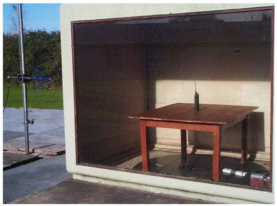
TEST REPORT No: EL2300/6019 COPY No: (see below) ISSUE No: 1 FCC ID: PPH0TXD20A0 REPORT ON THE CERTIFICATION TESTING OF A SAUER DANFOSS LTD. INTEGRAL BATTERY POWERED TRACKTRONIC RADIO REMOTE CONTROL SYSTEM Part No: PEG.TXD2.003.914 WITH RESPECT TO THE FCC 47CFR, Pt=s 15.209 & 15.249 INTENTIONAL RADIATOR SPECIFICATION TEST DATE(s): 6 th to 11 th June 2001 TESTED BY: .................................................... N ROCHE APPROVED BY: .................................................... S P HAYES ISSUE DATE: .................................................... Distribution Copy No=s:- 1 SAUER DANFOSS LTD. 2 TRL Compliance Services Ltd - TCB 3 TRL EMC Ltd. EL2300/6019 Page 1 of 32 RF196-iss01 CONTENTS page APPLICANT'S SUMMARY 3 CERTIFICATE OF CONFORMITY & COMPLIANCE 4 DESCRIPTION OF TRANSCEIVER 4 EQUIPMENT TEST CONDITIONS 5 TESTS REQUIRED 6 SAMPLE CALCULATIONS 6 TEST RESULTS 7 - 15 PHOTOGRAPHS ANNEX A [X] PHOTOGRAPH No 1: Test site with Tx. ANNEX A1 PHOTOGRAPH No 2: Tx, front view. ANNEX A2 PHOTOGRAPH No 3: Tx, PCB underside view. ANNEX A3 PHOTOGRAPH No 4: Tx, PCB, top. ANNEX A4 PHOTOGRAPH No 5: Tx/Rx pcb=s, underside. ANNEX A5 TEST EQUIPMENT LIST ANNEX B [X] APPLICANT'S SUBMISSION OF DOCUMENTATION LIST ANNEX C [X] Notes:- 1. Component failure during test YES [ ] NO [X] 2. If Yes, details of failure:- 3. The facilities used for the testing of the product contained in this report are FCC Listed. 4. The contents of the attached applicants declarations and other supplied information are not covered by the scope of this laboratory=s UKAS or FCC accreditations and is provided in good faith. EL2300/6019 Page 2 of 19 RF196-iss01 APPLICANT'S SUMMARY EQUIPMENT UNDER TEST (EUT): Part No: PEG.TXD2.003.914 EQUIPMENT TYPE: Remote Control Transmitter SERIAL NUMBER OF EUT: 05011CF PURPOSE OF TEST: FCC Certification TEST SPECIFICATION(s): FCC 47CFR Pt 15.249 TEST RESULT: COMPLIANT: Yes [X] No [ ] APPLICANT=S CATEGORY: ( a ) MANUFACTURER [X] ( b ) IMPORTER [ ] ( c ) DISTRIBUTOR [ ] ( d ) AGENT [ ] APPLICANT'S ORDER No(s): 4042 APPLICANT=S CONTACT PERSON(s): Mr. Charles Harlock APPLICANT: SAUER DANFOSS LTD., ADDRESS: Suite 1, Arden Court Arden Street Stratford-upon-Avon Warwickshire CV37 6NT UK Tel: +44 1789 207260 Fax: +44 1789 207270 MANUFACTURER: SAUER DANFOSS LTD., ADDRESS: Suite 1, Arden Court Arden Street Stratford-upon-Avon Warwickshire CV37 6NT UK Tel: +44 1789 207260 Fax: +44 1789 207270 EUT(s) COUNTRY OF ORIGIN: UNITED KINGDOM TEST LABORATORY: TRL EMC Ltd. UKAS ACCREDITATION No: 0728 TEST DATE(s): 7 to 11 June 2001 TEST REPORT No: EL2300/6019 EL2300/6019 Page 3 of 19 RF196-iss01 CERTIFICATE OF CONFORMITY & COMPLIANCE FCC IDENTITY: PPH0TXD2OA0 PURPOSE OF TEST: FCC Certification. TEST SPECIFICATION: FCC 47CFR, Parts 15.209, 15.249 TEST RESULT: Compliant to specification. EQUIPMENT UNDER TEST: Part No: PEG.TXD2.003.914 EQUIPMENT SERIAL No: 05011CF ITU EMISSION CODE: 7M5F1D EQUIPMENT TYPE: Remote Control Transmitter UTILISATION: Telecommand for outdoor machinery CARRIER EMISSION: +39.8mV/m @ 3m ANTENNA TYPE: Integral ALTERNATIVE AE: None, as per Part 15.203. BAND OF OPERATION: 902.000 – 928.000MHz CHANNEL SPACING: Not applicable. No. of CHANNELS: 1 (one). FREQUENCY GENERATION: SAW Resonator [ ] ; Crystal [X] ; Synthesizer [ ] MODULATION METHOD: Amplitude [ ] ; Digital [X] ; Angle [ ] POWER SOURCE(s): +9Vdc, integral battery powered only. TEST DATE(s): 6 to 11 June 2001 ORDER No(s): 4042 APPLICANT: Suite 1, Arden Court Arden Street Stratford-upon-Avon Warwickshire CV37 6NT UK TESTED BY: ............................................................... N ROCHE APPROVED BY: ............................................................... S P HAYES EMC MANAGER EL2300/6019 Page 4 of 19 RF196-iss01 EQUIPMENT TEST CONDITIONS 1. EQUIPMENT SERIAL / MODEL IDENTITY CHANNEL NUMBER Tx NOMINAL FREQUENCY MHz Rx NOMINAL FREQUENCY MHz TESTS REQUIRED REMARKS Tx radiated Pt. 15.209 Tx carrier Pt. 15.249 PEG.TXD2.003.914 1 914.540MHz 914.54MHz 2. Equipment category: Single channel [X] Two channel [ ] Multi-channel [ ] 3. Supply voltages: Vnom = +9.0Vdc Note:- Vnom voltages are as stated above unless otherwise shown on the test report page. 4. Temperatures: (Ambient) Tnom = [see test] 5. Transmitter maximum deviation or shift: kHz = n/a 6. Transmitter maximum bit or pulse rate & level: bps = 50kb/s Level = TTL 7. Channel spacing: kHz = n/a Narrowband [ ] Wholeband [X] EL2300/6019 Page 5 of 19 RF196-iss01 TESTS REQUIRED TRANSMITTER TESTS Transmitter Spurious Emissions - Powerline - Part 15.207 [n/a] Transmitter Spurious Emissions - Radiated - Part 15.209. [X] Transmitter Carrier Emission - Radiated - Part 15.249. [X] Transmitter Carrier Frequency - Radiated - Part 15.249. [X] Notes:- 1. Equipment tested for (mains ac) 110V powerline emissions. [n/a] 2. Equipment tested as (fixed) integral antenna configuration. [ X] 3. All tests were carried out with new batteries, as per Part 15.31.e. [n/a] 4. Equipment tested for radiated emissions as per Part 15.209. [X] 5. Equipment tested for radiated emissions as per Part 15.249. [X] 6. Equipment tested for unintentional radiator digital device Class B. [N/A] SAMPLE CALCULATIONS Parts 15.209 & 15.249 - Radiated. Frequency (MHz) Rx (dBFV) Ae AF & Cable loss (dB/m & dB) Field Strength @ 3m (dBFV/m) 914.54 71.0 21.0 92.0 (39.8mV/m) Notes:- 1. Unit under test (EUT) is to be integral battery powered when in commercial use. EL2300/6019 Page 6 of 19 RF196-iss01 TRANSMITTER TESTS TRANSMITTER SPURIOUS EMISSIONS - RADIATED - PART 15.209 Ambient temperature = +23EC (<1GHz), EC (>1GHz) 3m measurements <1GHz [X] Relative humidity = 35% (<1GHz), % (>1GHz) 1m measurements >1GHz [ ] Conditions = Open Area Test Site (OATS) 3m extrapolated from 1m [ ] Supply voltage = Vnom Channel number = 1 Frequency & Level 30MHz to 88MHz nil emissions $-20dB below limit Frequency & Level 88MHz to 216MHz nil emissions $-20dB below limit Frequency & Level 216MHz to 960MHz 914.54MHz 92. 0dBFV/m Frequency & Level 960M…
Text truncated - open the document above for the full version.
Test Report
TEST REPORT No: EL2300/6019 COPY No: (see below) ISSUE No: 1 FCC ID: PPH0TXD20A0 REPORT ON THE CERTIFICATION TESTING OF A SAUER DANFOSS LTD. INTEGRAL BATTE…
Text truncated - open the document above for the full version.
Contact Information
Applicant
Charles Harlock(Commercial Manager)
Technical Contact
Sauer-Danfoss LtdMike Hallett
[email protected]+44 1789 207260
Suite 1, Arden Court · Statford-upon-Avon · United Kingdom
Non-Technical Contact
Sauer Danfoss LtdCharles Harlock
[email protected]+44 1789 207260
Test Firm
TRL EMC LimitedNeil Roche
Technical Specifications
| # | Rule Parts | Frequency Range | Power Output | Emission |
|---|---|---|---|---|
| 1 | 15C | 914.5 MHz - 914.5 MHz | - | 7M5F1D |